2006 LAND ROVER FRELANDER 2 brake
[x] Cancel search: brakePage 1792 of 3229
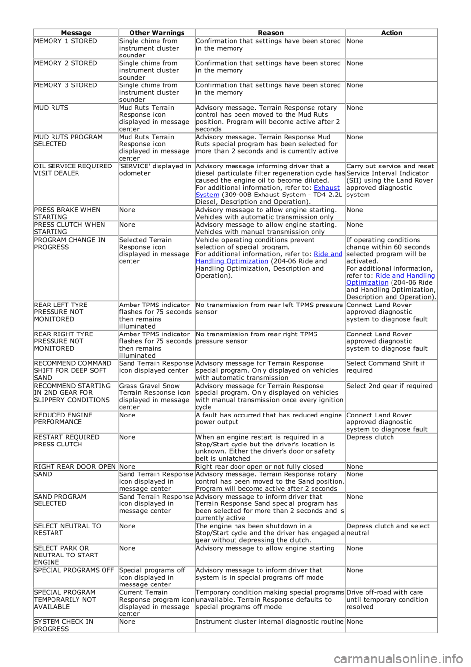
MessageO ther WarningsReasonAction
MEMORY 1 STOREDSingle chime fromins trument cl ust ers ounder
Confirmati on t hat s et ti ngs have been s toredin the memoryNone
MEMORY 2 STOREDSingle chime fromins trument cl ust ers ounder
Confirmati on t hat s et ti ngs have been s toredin the memoryNone
MEMORY 3 STOREDSingle chime fromins trument cl ust ers ounder
Confirmati on t hat s et ti ngs have been s toredin the memoryNone
MUD RUTSMud Ruts Terrai nRespons e icondis played in mess agecent er
Advi sory mes s age. Terrain Res pons e rotarycont rol has been moved to the Mud Rut spos i ti on. Program wi ll become act ive after 2s econds
None
MUD RUTS PROGRAMSELECTEDMud Ruts Terrai nRespons e icondis played in mess agecent er
Advi sory mes s age. Terrain Res pons e MudRuts s peci al program has been s elect ed formore than 2 seconds and is current ly act ive
None
OIL SERVICE REQUIREDVISIT DEALER'SERVICE' dis played inodomet erAdvi sory mes s age informing driver that adies el parti culat e fil ter regenerat ion cycl e hascaus ed t he engi ne oil t o become dilut ed.For addit ional informati on, refer t o: Exhaus tSys t em (309-00B Exhaus t Syst em - TD4 2.2LDies el, Des cript ion and Operat ion).
Carry out s ervi ce and res etServi ce Int erval Indicator(SII) us ing t he Land Roverapproved di agnos ti csys tem
PRESS BRAKE W HENSTARTINGNoneAdvi sory mes s age to al low engi ne st art ing.Vehi cl es wit h aut omati c trans mi s si on onlyNone
PRESS CLUTCH W HENSTARTINGNoneAdvi sory mes s age to al low engi ne st art ing.Vehi cl es wit h manual transmis s ion onlyNone
PROGRAM CHANGE INPROGRESSSel ect ed TerrainRespons e icondis played in mess agecent er
Vehi cl e operat ing condi ti ons prevents el ect ion of s peci al program.For addit ional informati on, refer t o: Ride andHandl ing Opt imi zat ion (204-06 Ri de andHandl ing Opt imi zat ion, Des cript ion andOperati on).
If operat ing condi ti onschange wit hin 60 secondssel ect ed program wil l beact ivated.For addit ional i nformati on,refer t o: Ride and Handli ngOpt imizati on (204-06 Rideand Handli ng Opt imi zat ion,Des cri pti on and Operati on).
REAR LEFT TY REPRESSURE NOTMONITORED
Amber TPMS indicatorfl ashes for 75 secondsthen remainsil lumi nat ed
No t rans mis s ion from rear l eft TPMS pres s ures ens orConnect Land Roverapproved di agnos ti csys tem t o diagnos e fault
REAR RIGHT TY REPRESSURE NOTMONITORED
Amber TPMS indicatorfl ashes for 75 secondsthen remainsil lumi nat ed
No t rans mis s ion from rear right TPMSpres sure s ensorConnect Land Roverapproved di agnos ti csys tem t o diagnos e fault
RECOMMEND COMMANDSHIFT FOR DEEP SOFTSAND
Sand Terrai n Respons eicon dis played cent erAdvi sory mes s age for Terrai n Res pons es pecial program. Only dis played on vehicleswit h automat ic trans mi ss i on
Sel ect Command Shi ft i frequired
RECOMMEND STARTINGIN 2ND GEAR FO RSLIPPERY CONDITIONS
Gras s Gravel SnowTerrai n Res pons e i condis played in mess agecent er
Advi sory mes s age for Terrai n Res pons es pecial program. Only dis played on vehicleswit h manual trans mi s si on once every ignit ioncycle
Sel ect 2nd gear if requi red
REDUCED ENGINEPERFO RMANCENoneA faul t has occurred t hat has reduced enginepower out putConnect Land Roverapproved di agnos ti csys tem t o diagnos e faultRESTART REQ UIREDPRESS CLUTCHNoneW hen an engine res tart is requi red i n aStop/St art cycl e but the driver’s locati on isunknown. Eit her t he dri ver’s door or s afetybel t is unl atched
Depress cl ut ch
RIGHT REAR DOOR OPENNoneRight rear door open or not ful ly clos edNoneSANDSand Terrai n Respons eicon dis played inmes sage center
Advi sory mes s age. Terrain Res pons e rotarycont rol has been moved to the Sand pos it ion.Program wil l become act ive aft er 2 s econds
None
SAND PROGRAMSELECTEDSand Terrai n Respons eicon dis played inmes sage center
Advi sory mes s age to inform driver thatTerrai n Res pons e Sand s pecial program hasbeen sel ect ed for more t han 2 s econds and iscurrent ly acti ve
None
SELECT NEUTRAL TORESTARTNoneThe engi ne has been shut down in aStop/St art cycl e and t he dri ver has engaged agear wi thout depres si ng the cl utch.
Depress cl ut ch and s electneut ral
SELECT PARK ORNEUTRAL TO STARTENGINE
NoneAdvi sory mes s age to al low engi ne st art ingNone
SPECIAL PROGRAMS OFFSpecial programs officon dis played inmes sage center
Advi sory mes s age to inform driver thats ys t em i s in special programs off modeNone
SPECIAL PROGRAMTEMPORARILY NOTAVAILABLE
Current TerrainRespons e program icondis played in mess agecent er
Temporary condit ion making special programsunavail abl e. Terrai n Respons e default s t os pecial programs off mode
Drive off-road wit h careunt il t emporary condit ionres ol ved
SY STEM CHECK INPROGRESSNoneIns t rument clus ter int ernal diagnos t ic rout ineNone
Page 1794 of 3229
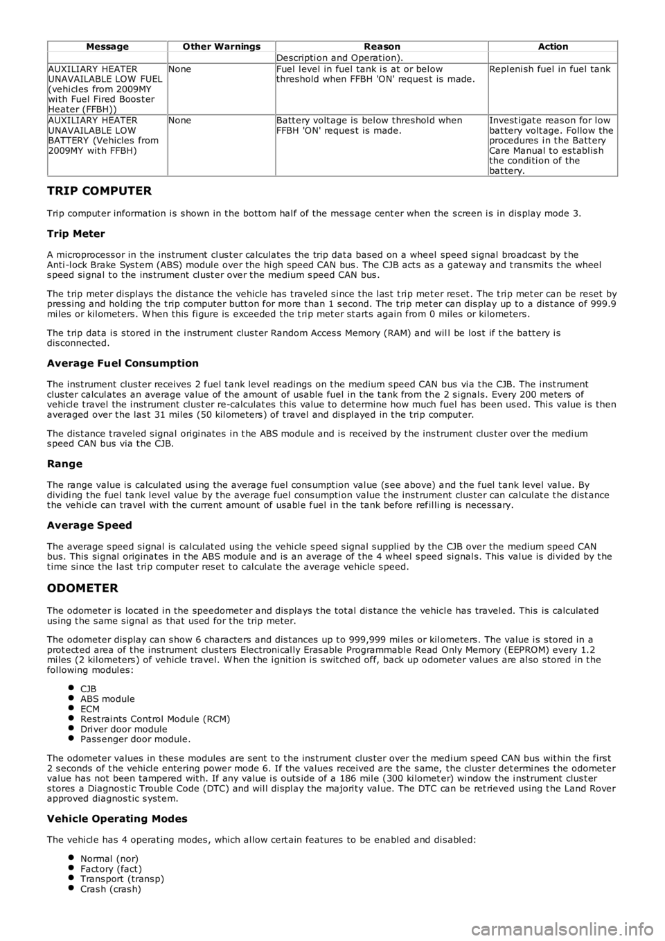
MessageO ther WarningsReasonAction
Descripti on and Operat ion).
AUXILIARY HEATERUNAVAILABLE LOW FUEL(vehi cl es from 2009MYwi th Fuel Fired Boos t erHeater (FFBH))
NoneFuel l evel in fuel tank i s at or bel owthreshold when FFBH 'ON' reques t is made.Repl eni sh fuel in fuel tank
AUXILIARY HEATERUNAVAILABLE LOWBATTERY (Vehicles from2009MY wit h FFBH)
NoneBatt ery volt age is bel ow t hres hol d whenFFBH 'ON' reques t is made.Invest igat e reas on for l owbat tery volt age. Follow theprocedures i n t he Batt eryCare Manual t o es t abl is hthe condi ti on of thebat tery.
TRIP COMPUTER
Tri p comput er informat ion i s s hown in t he bott om hal f of the mes s age cent er when the s creen i s in dis play mode 3.
Trip Meter
A microprocess or in the ins trument cl us t er calculat es the trip dat a based on a wheel speed s ignal broadcas t by t heAnti -l ock Brake Sys t em (ABS) modul e over the hi gh speed CAN bus . The CJB act s as a gat eway and t ransmit s t he wheels peed si gnal t o t he ins trument cl ust er over t he medium s peed CAN bus .
The t rip meter di spl ays t he dis t ance t he vehicle has t raveled s i nce t he l as t t ri p met er res et . The t ri p met er can be reset bypres s ing and holdi ng the t rip computer butt on for more t han 1 s econd. The t ri p met er can dis play up to a dis t ance of 999.9mi les or kil omet ers . W hen this fi gure is exceeded the t ri p met er st art s again from 0 miles or ki lometers .
The t rip dat a i s s tored in the i nst rument clus t er Random Acces s Memory (RAM) and will be los t if t he batt ery i sdis connected.
Average Fuel Consumption
The ins t rument clus ter receives 2 fuel t ank level readings on t he medium s peed CAN bus vi a t he CJB. The i nst rumentclus ter calcul ates an average value of t he amount of usable fuel in the t ank from t he 2 s i gnal s. Every 200 meters ofvehi cl e t ravel the i nst rument clus t er re-calculat es this val ue to det ermine how much fuel has been us ed. Thi s value i s thenaveraged over t he las t 31 mi les (50 kil ometers ) of t ravel and di s pl ayed in t he t ri p comput er.
The dis t ance t raveled s ignal ori gi nates i n t he ABS module and i s received by t he inst rument clus ter over t he medi ums peed CAN bus via t he CJB.
Range
The range value i s calculated us i ng the average fuel cons umpt ion val ue (s ee above) and t he fuel t ank level val ue. Bydividi ng the fuel tank l evel val ue by t he average fuel cons umpti on value t he ins t rument clus ter can cal cul at e t he dis t ancet he vehi cl e can travel wi th the current amount of us abl e fuel i n t he tank before refil li ng is necess ary.
Average Speed
The average s peed s i gnal is cal cul at ed us ing t he vehi cle s peed s ignal s uppli ed by the CJB over the medium speed CANbus. This si gnal originat es in t he ABS module and is an average of t he 4 wheel s peed si gnal s. This val ue is di vided by t het ime si nce the l ast t ri p computer res et t o cal cul ate the average vehicle s peed.
ODOMETER
The odometer is locat ed i n the speedometer and dis plays t he tot al di s tance the vehicl e has travel ed. This is calculat edus ing t he s ame s ignal as that us ed for t he trip meter.
The odometer dis play can s how 6 characters and dis t ances up t o 999,999 mi les or kil ometers . The value i s s tored in aprot ect ed area of t he ins t rument clus ters Electroni cal ly Eras able Programmabl e Read Only Memory (EEPROM) every 1.2mi les (2 kil ometers ) of vehicle t ravel. W hen the i gnit ion i s s wit ched off, back up odomet er val ues are al so s tored in t hefol lowing modul es:
CJBABS moduleECMRest rai nts Cont rol Modul e (RCM)Dri ver door modulePass enger door module.
The odometer values in thes e modules are s ent t o t he ins t rument clus ter over t he medi um s peed CAN bus wit hin the firs t2 s econds of t he vehi cl e entering power mode 6. If the values received are t he s ame, t he clus ter det ermi nes t he odometervalue has not been tampered wit h. If any value i s outs ide of a 186 mil e (300 ki lometer) wi ndow the i nst rument clus t ers tores a Diagnos ti c Trouble Code (DTC) and wil l di spl ay the majori ty val ue. The DTC can be ret rieved us ing t he Land Roverapproved diagnos t ic s yst em.
Vehicle Operating Modes
The vehi cl e has 4 operat ing modes , which al low cert ain features to be enabl ed and dis abl ed:
Normal (nor)Fact ory (fact )Trans port (trans p)Cras h (cras h)
Page 1800 of 3229
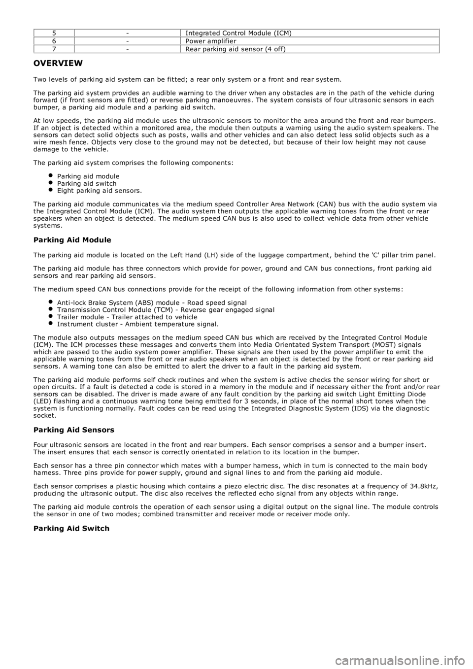
5-Integrat ed Cont rol Module (ICM)
6-Power amplifier
7-Rear parking aid s ens or (4 off)
OVERVIEW
Two l evels of parki ng aid sys tem can be fit ted; a rear only sys t em or a front and rear s yst em.
The parking ai d s yst em provi des an audi ble warning t o t he dri ver when any obs tacles are in the pat h of the vehicle duringforward (i f front s ensors are fi tt ed) or revers e parking manoeuvres . The sys tem consi st s of four ult ras onic s ensors in eachbumper, a parki ng aid modul e and a parki ng aid s wi tch.
At low s peeds , the parki ng aid modul e us es the ul trasonic sens ors t o moni tor t he area around t he front and rear bumpers .If an object i s detected wit hin a monit ored area, t he module t hen outputs a warni ng usi ng t he audi o s ys t em s peakers. Thes ens ors can det ect s oli d objects such as pos ts , wall s and other vehicles and can also det ect l es s s oli d objects such as awire mes h fence. Object s very clos e t o t he ground may not be det ect ed, but becaus e of t hei r low hei ght may not causedamage to the vehicle.
The parking ai d s yst em compris es the foll owing component s:
Parking ai d moduleParking ai d s wit chEight parking ai d s ens ors.
The parking ai d module communi cat es via t he medium s peed Cont roll er Area Net work (CAN) bus wit h t he audi o s yst em vi at he Int egrated Cont rol Modul e (ICM). The audi o s yst em then output s t he appl icabl e warni ng t ones from the front or rears peakers when an object is detect ed. The medi um s peed CAN bus is al s o us ed to col lect vehicle dat a from other vehi cles ys t ems .
Parking Aid Module
The parking ai d module is l ocat ed on the Left Hand (LH) s ide of t he l uggage compart ment , behind t he 'C' pil lar trim panel .
The parking ai d module has t hree connect ors whi ch provide for power, ground and CAN bus connecti ons , front parking ai ds ens ors and rear parking ai d s ens ors .
The medium s peed CAN bus connect ions provi de for t he receipt of the foll owing i nformat ion from ot her s ys tems :
Anti -l ock Brake Sys t em (ABS) modul e - Road s peed si gnalTrans mis s ion Cont rol Modul e (TCM) - Reverse gear engaged si gnalTrai ler module - Trailer at tached to vehicl eIns t rument clus ter - Ambi ent t emperat ure s ignal.
The module al so out puts mess ages on t he medium speed CAN bus whi ch are recei ved by the Int egrated Control Modul e(ICM). The ICM proces s es t hes e mes s ages and convert s t hem int o Media Ori ent ated Sys tem Trans port (MOST) s i gnal swhich are pass ed t o t he audi o s yst em power ampl ifi er. These s ignal s are then us ed by t he power ampl ifier t o emit theappl icable warning t ones from t he front or rear audi o s peakers when an object i s detected by the front or rear parki ng aids ens ors . A warning t one can als o be emi tt ed t o alert the driver to a faul t in the parki ng aid s ys tem.
The parking ai d module performs s elf check rout ines and when t he s yst em is acti ve checks the sens or wiring for short oropen ci rcuit s . If a fault i s detected a code i s s tored in a memory in the modul e and if neces s ary ei ther t he front and/or rears ens ors can be dis abl ed. The driver is made aware of any faul t condit ion by the parki ng aid s wi tch Light Emi tt ing Di ode(LED) flas hing and a conti nuous warning t one bei ng emi tt ed for 3 seconds , in place of the normal short tones when t hes ys t em i s functi oning normal ly. Faul t codes can be read usi ng t he Int egrated Di agnost ic Syst em (IDS) vi a t he diagnost ics ocket.
Parking Aid Sensors
Four ul trasonic sens ors are located i n t he front and rear bumpers . Each s ens or compri s es a s ens or and a bumper ins ert .The ins ert ens ures t hat each s ensor i s correctl y ori entat ed in relat ion t o i ts l ocation i n t he bumper.
Each sens or has a three pin connect or which mat es wit h a bumper harnes s, whi ch in t urn is connect ed to the main bodyharnes s. Three pi ns provide for power s upply, ground and s ignal lines t o and from the parki ng aid modul e.
Each sens or compris es a pl as t ic hous ing which contai ns a piezo elect ric di s c. The disc res onat es at a frequency of 34.8kHz,produci ng t he ult ras oni c output. The di sc al s o receives t he reflected echo s ignal from any objects wit hi n range.
The parking ai d module controls t he operat ion of each sens or usi ng a digi tal output on t he s ignal line. The module controlst he sens or in one of t wo modes ; combi ned transmit ter and receiver mode or receiver mode only.
Parking Aid Switch
Page 1802 of 3229
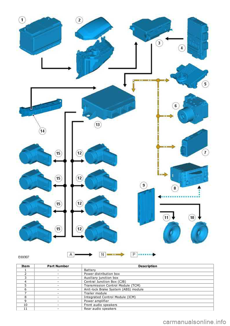
ItemPart NumberDescription
1-Bat tery2-Power dis t ri but ion box
3-Auxil iary juncti on box
4-Cent ral Juncti on Box (CJB)5-Trans mi s si on Control Module (TCM)
6-Ani t-lock Brake Sys tem (ABS) module
7-Trailer module8-Integrat ed Control Modul e (ICM)
9-Power ampli fi er
10-Front audio speakers11-Rear audio s peakers
Page 1811 of 3229
Publi s hed: 11-May-2011
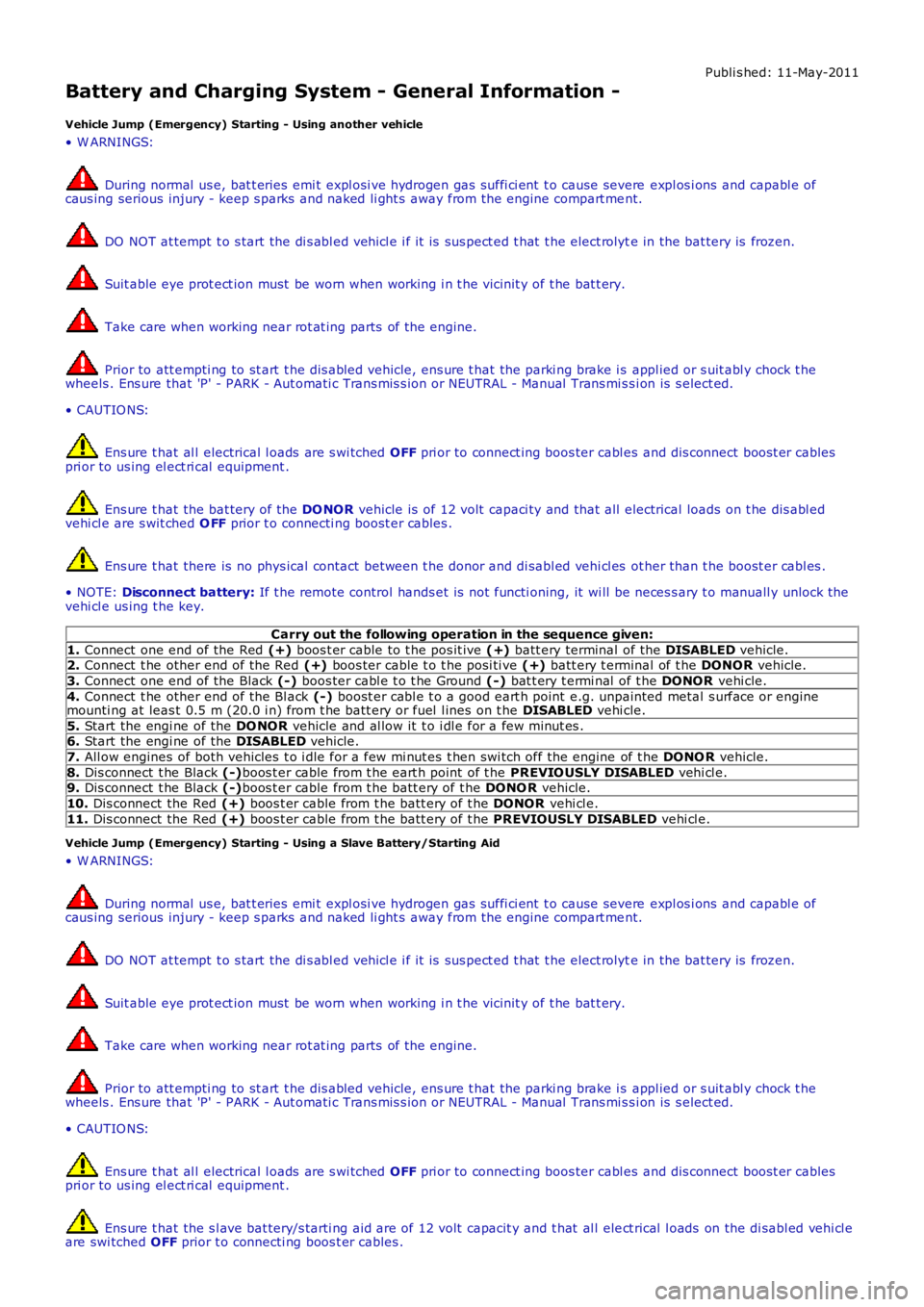
Battery and Charging System - General Information -
Vehicle Jump (Emergency) Starting - Using another vehicle
• W ARNINGS:
During normal us e, bat t eries emi t expl osi ve hydrogen gas suffi ci ent t o cause severe expl os i ons and capabl e ofcaus ing serious injury - keep s parks and naked li ght s away from the engine compart ment.
DO NOT at tempt t o s tart the di s abl ed vehi cl e i f it is sus pect ed t hat t he elect rolyte in the bat tery is frozen.
Suit able eye prot ect ion must be worn when working i n t he vicinit y of t he bat t ery.
Take care when working near rot at ing parts of t he engine.
Prior to att empti ng to st art t he dis abled vehicle, ens ure t hat the parki ng brake i s appl ied or s uit abl y chock t hewheels . Ens ure that 'P' - PARK - Aut omati c Trans mis s ion or NEUTRAL - Manual Trans mi ss i on is s elect ed.
• CAUTIO NS:
Ens ure t hat al l electrical l oads are s wi tched OFF pri or to connect ing boos ter cabl es and dis connect boos t er cablespri or to us ing el ect ri cal equipment .
Ens ure t hat the bat tery of the DO NOR vehicle is of 12 volt capaci ty and that all electrical loads on t he dis abl edvehi cl e are s wit ched O FF prior t o connecti ng boost er cables .
Ens ure t hat there is no phys ical contact between t he donor and di sabl ed vehi cl es other than t he boost er cabl es .
• NOTE: Disconnect battery: If t he remote control hands et is not functi oning, it wi ll be neces s ary t o manuall y unlock thevehi cl e us ing t he key.
Carry out the following operation in the sequence given:
1. Connect one end of the Red (+) boos t er cable to t he pos it ive (+) batt ery terminal of the DISABLED vehicle.2. Connect t he other end of the Red (+) boos ter cable t o t he posi ti ve (+) batt ery t erminal of t he DONOR vehicle.
3. Connect one end of the Black (-) boos ter cabl e t o t he Ground (-) bat t ery t ermi nal of t he DONOR vehi cle.
4. Connect t he other end of the Bl ack (-) boost er cabl e t o a good eart h point e.g. unpainted metal s urface or enginemounti ng at leas t 0.5 m (20.0 i n) from t he batt ery or fuel l ines on t he DISABLED vehi cle.
5. Start the engi ne of the DO NOR vehicle and al low it t o i dl e for a few minut es .6. Start the engi ne of the DISABLED vehicle.
7. All ow engines of both vehicles t o i dle for a few mi nut es t hen swi tch off the engine of t he DONO R vehicle.
8. Dis connect t he Black (-)boos t er cable from t he eart h point of t he PREVIO USLY DISABLED vehi cl e.9. Dis connect t he Black (-)boos t er cable from t he batt ery of t he DONO R vehicle.
10. Dis connect the Red (+) boos t er cable from t he batt ery of t he DONOR vehi cl e.
11. Dis connect the Red (+) boos t er cable from t he batt ery of t he PREVIOUSLY DISABLED vehi cl e.
Vehicle Jump (Emergency) Starting - Using a Slave Battery/Starting Aid
• W ARNINGS:
During normal us e, bat t eries emi t expl osi ve hydrogen gas suffi ci ent t o cause severe expl os i ons and capabl e ofcaus ing serious injury - keep s parks and naked li ght s away from the engine compart ment.
DO NOT at tempt t o s tart the di s abl ed vehi cl e i f it is sus pect ed t hat t he elect rolyte in the bat tery is frozen.
Suit able eye prot ect ion must be worn when working i n t he vicinit y of t he bat t ery.
Take care when working near rot at ing parts of t he engine.
Prior to att empti ng to st art t he dis abled vehicle, ens ure t hat the parki ng brake i s appl ied or s uit abl y chock t hewheels . Ens ure that 'P' - PARK - Aut omati c Trans mis s ion or NEUTRAL - Manual Trans mi ss i on is s elect ed.
• CAUTIO NS:
Ens ure t hat al l electrical l oads are s wi tched OFF pri or to connect ing boos ter cabl es and dis connect boos t er cablespri or to us ing el ect ri cal equipment .
Ens ure t hat the s l ave bat tery/s tarti ng aid are of 12 volt capacit y and t hat al l elect rical l oads on the di sabl ed vehi cl eare swi tched OFF prior t o connecti ng boos t er cables .
Page 1827 of 3229
Publi s hed: 11-May-2011
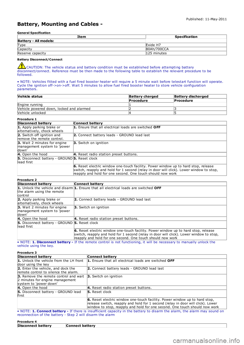
Battery, Mounting and Cables -
General SpecificationItemSpecification
Battery - All models:
TypeExide H7Capaci ty80Ah/700CCA
Res erve capacit y125 minutes
Battery Disconnect/C onnect
CAUTION: The vehicle s t atus and batt ery condit ion mus t be es t abl is hed before att empti ng bat t erydis connect/connect . Reference mus t be t hen made t o t he fol lowing table to es t abl is h t he rel evant procedure t o befol lowed.
• NOTE: Vehicles fit ted wit h a fuel fired boos t er heat er will requi re a 5 mi nute wait before tel es t art funct ion wi ll operate.Cycl e t he ignit ion off->on->off. W ai t 5 mi nutes t o all ow fuel fired boos t er heat er to s t ore vehicle confi gurati onparamet ers .
Vehicle statusBattery chargedBattery discharged
ProcedureProcedure
Engine runni ng1Vehicle powered down, l ocked and alarmed23
Vehicle unl ocked45
Procedure 1
Disconnect batteryConnect battery1. Apply parki ng brake oralt ernat ively, chock wheels1. Ens ure that all el ect ri cal loads are s wit ched O FF
2. Swit ch off i gni ti on andremove the remote cont rol.2. Connect bat t ery l eads - GROUND lead l ast
3. W ai t 2 mi nut es for enginemanagement sys tem t o 'powerdown'
3. Swit ch on ignit ion
4. Open t he hood4. Reset radi o s tat ion preset but tons .
5. Dis connect batt ery - GROUNDl ead firs t5. Reset clock
6. Reset elect ric window one-t ouch facili ty. Power window up t o hard s top, rel eas es wit ch, reapply and hol d for 1 s econd (relay i n door wil l cl ick). Lower window t o s top,reapply and hold for one s econd. One t ouch s hould now work
Procedure 2
Disconnect batteryConnect battery
1. Unlock t he vehi cl e and dis armt he alarm us ing t he remotecont rol
1. Ensure t hat al l el ect ri cal l oads are s wit ched OFF
2. Apply parki ng brake oralt ernat ively, chock wheels2. Connect batt ery l eads - GROUND l ead las t
3. W ai t 2 mi nut es for enginemanagement sys tem t o 'powerdown'
3. Swit ch on i gni ti on
4. Open t he hood4. Res et radio s t ati on pres et but tons .
5. Dis connect batt ery - GROUNDl ead firs t5. Res et cl ock
6. Res et el ect ri c window one-touch facil it y. Power window up to hard s top, rel eases wit ch, reappl y and hold for 1 s econd (rel ay in door wil l cl ick). Lower window t o s top,reapply and hol d for one s econd. One t ouch should now work
• NOTE: 1. Disconnect battery - If the remot e cont rol is not funct ioning, it will be necess ary to manual ly unlock thevehi cl e us ing t he key.
Procedure 3
Disconnect batteryConnect battery1. Unlock t he vehi cl e from the LH frontdoor us i ng the key1. Ens ure t hat al l electrical l oads are s wi tched OFF
2. Enter t he vehi cl e, and dock t heremote control to si lence the al arm.2. Connect batt ery leads - GROUND l ead las t
3. Remove t he remot e cont rol and wai t2 minutes for engi ne managements yst em to 'power down'
3. Swi tch on i gni ti on
4. Open t he hood4. Res et radio st ati on pres et but t ons .
5. Dis connect batt ery - GROUND leadfirst5. Res et cl ock
6. Res et el ect ri c wi ndow one-touch facil it y. Power wi ndow up to hard s t op,release s wit ch, reapply and hol d for 1 second (relay i n door wil l cl ick). Lowerwi ndow to s top, reapply and hold for one s econd. One t ouch s hould now work
• NOTE: 1. Connect battery - If there is ins uffi cient capacit y in the bat tery to di s arm the al arm, t he alarm may sound onreconnect ion of t he bat t ery - St ep 2 wi ll dis arm t he alarm
Procedure 4
Disconnect batteryConnect battery
Page 1828 of 3229
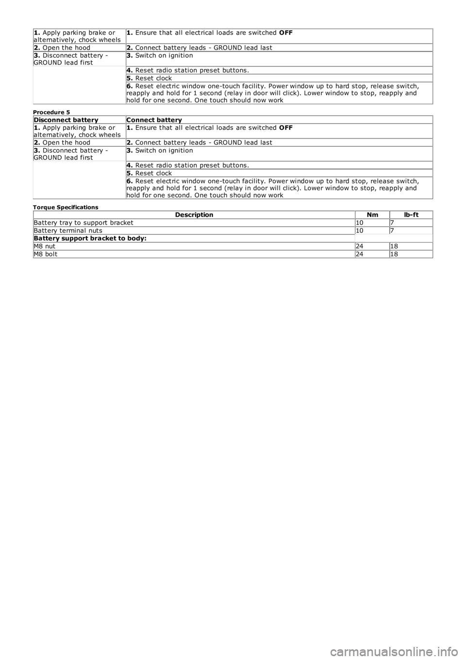
1. Apply parki ng brake oralt ernat ively, chock wheels1. Ens ure t hat al l elect rical l oads are s wit ched OFF
2. Open t he hood2. Connect batt ery leads - GROUND l ead las t3. Dis connect batt ery -GROUND lead firs t3. Swit ch on i gni ti on
4. Res et radio s t ati on pres et but tons .
5. Res et cl ock
6. Res et el ect ri c window one-touch facil it y. Power wi ndow up to hard s t op, release swit ch,reapply and hol d for 1 s econd (relay i n door wil l cl ick). Lower window t o s top, reapply andhold for one s econd. One t ouch s houl d now work
Procedure 5
Disconnect batteryConnect battery1. Apply parki ng brake oralt ernat ively, chock wheels1. Ens ure t hat al l elect rical l oads are s wit ched OFF
2. Open t he hood2. Connect batt ery leads - GROUND l ead las t
3. Dis connect batt ery -GROUND lead firs t3. Swit ch on i gni ti on
4. Res et radio s t ati on pres et but tons .
5. Res et cl ock
6. Res et el ect ri c window one-touch facil it y. Power wi ndow up to hard s t op, release swit ch,reapply and hol d for 1 s econd (relay i n door wil l cl ick). Lower window t o s top, reapply andhold for one s econd. One t ouch s houl d now work
Torque SpecificationsDescriptionNmlb-ft
Batt ery tray to support bracket107
Batt ery terminal nut s107Battery support bracket to body:
M8 nut2418
M8 bol t2418
Page 1834 of 3229
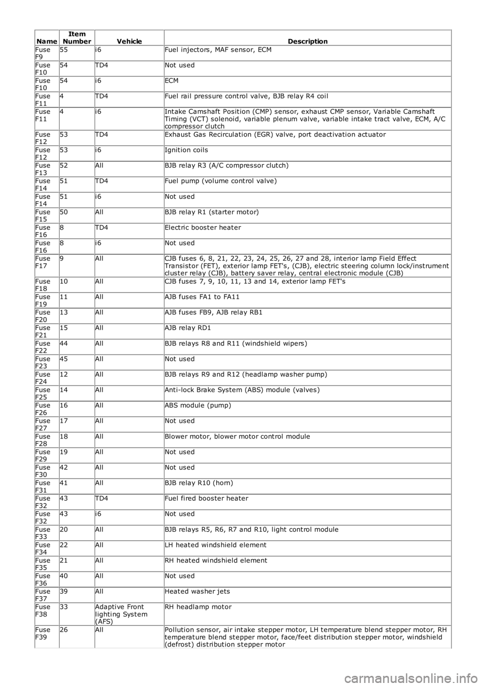
NameItemNumberVehicleDescription
FuseF955i 6Fuel inject ors , MAF s ens or, ECM
FuseF1054TD4Not us ed
FuseF1054i 6ECM
FuseF114TD4Fuel rai l press ure cont rol valve, BJB relay R4 coi l
FuseF114i 6Int ake Cams haft Pos it ion (CMP) s ens or, exhaust CMP sens or, Vari able Cams haftTi ming (VCT) s olenoi d, variable pl enum valve, variable intake t ract valve, ECM, A/Ccompres s or cl utch
FuseF1253TD4Exhaust Gas Recircul ati on (EGR) valve, port deact ivati on act uator
FuseF1253i 6Ignit ion coil s
FuseF1352AllBJB relay R3 (A/C compres sor clut ch)
FuseF1451TD4Fuel pump (vol ume cont rol valve)
FuseF1451i 6Not us ed
FuseF1550AllBJB relay R1 (s tarter mot or)
FuseF168TD4El ect ri c boos t er heat er
FuseF168i 6Not us ed
FuseF179AllCJB fus es 6, 8, 21, 22, 23, 24, 25, 26, 27 and 28, i nt eri or lamp Fi el d EffectTransi st or (FET), ext erior l amp FET's , (CJB), electric st eering col umn lock/i ns t rumentcl us t er relay (CJB), batt ery s aver relay, cent ral electronic module (CJB)
FuseF1810AllCJB fus es 7, 9, 10, 11, 13 and 14, ext erior l amp FET's
FuseF1911AllAJB fus es FA1 to FA11
FuseF2013AllAJB fus es FB9, AJB rel ay RB1
FuseF2115AllAJB relay RD1
FuseF2244AllBJB relays R8 and R11 (winds hield wipers )
FuseF2345AllNot us ed
FuseF2412AllBJB relays R9 and R12 (headl amp was her pump)
FuseF2514AllAnt i-lock Brake Sys tem (ABS) module (valves )
FuseF2616AllABS modul e (pump)
FuseF2717AllNot us ed
FuseF2818AllBl ower motor, bl ower motor cont rol module
FuseF2919AllNot us ed
FuseF3042AllNot us ed
FuseF3141AllBJB relay R10 (horn)
FuseF3243TD4Fuel fi red boos ter heater
FuseF3243i 6Not us ed
FuseF3320AllBJB relays R5, R6, R7 and R10, l ight cont rol module
FuseF3422AllLH heat ed wi nds hield element
FuseF3521AllRH heat ed wi nds hiel d element
FuseF3640AllNot us ed
FuseF3739AllHeat ed was her jets
FuseF3833Adapti ve Frontl ighti ng Sys t em(AFS)
RH headl amp mot or
FuseF3926AllPol luti on s ens or, ai r int ake st epper mot or, LH t emperat ure bl end st epper mot or, RHtemperat ure bl end st epper mot or, face/feet dis t ri but ion s t epper mot or, wi nds hield(defrost ) dis t ri but ion s t epper mot or