2006 LAND ROVER FRELANDER 2 brake
[x] Cancel search: brakePage 2881 of 3229
161
Maintenance
R
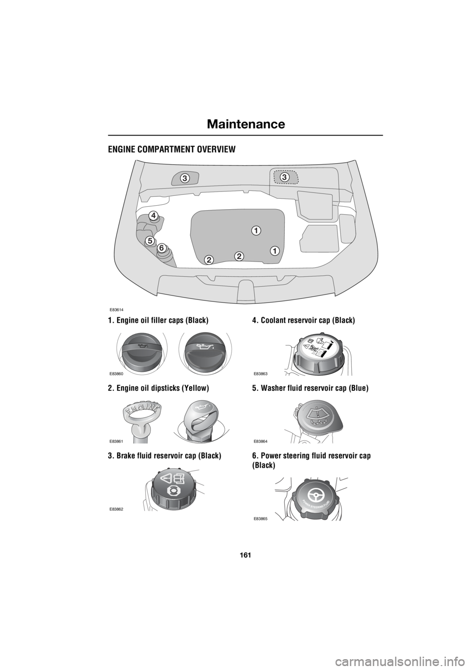
ENGINE COMPARTMENT OVERVIEW
1. Engine oil filler caps (Black)
2. Engine oil dipsticks (Yellow)
3. Brake fluid reservoir cap (Black) 4. Coolant reservoir cap (Black)
5. Washer fluid reservoir cap (Blue)
6. Power steering fluid reservoir cap
(Black)
3
4
56
21
3
1
2
E83614
E83860
E83861
E83862
E83863
E83864
E83865
Page 2885 of 3229
165
Maintenance
R
BRAKE AND CLUTCH FLUID CHECK
If the quantity of fluid in the
brake/clutch rese rvoir drops below
the recommended level, a red
warning indicator in the instrument pack will
illuminate or the message CHECK BRAKE
FLUID will be displayed in the message centre.
Note: If the warning indicator illuminates, or
the message is displayed while the vehicle is
being driven, stop the vehi cle as soon as safety
permits by gently applying the brakes.
Check and top-up the flui d level if necessary.
Checking the fluid level
With the vehicle on level ground, check the
fluid level at least every week (more frequently
in high mileage or arduous operating
conditions).
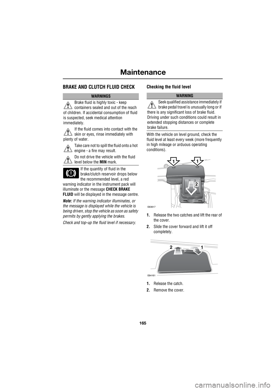
1. Release the two catches and lift the rear of
the cover.
2. Slide the cover forward and lift it off
completely.
1. Release the catch.
2. Remove the cover.
WARNINGS
Brake fluid is highly toxic - keep
containers sealed a nd out of the reach
of children. If accident al consumption of fluid
is suspected, seek medical attention
immediately.
If the fluid comes into contact with the
skin or eyes, rinse immediately with
plenty of water.
Take care not to spill the fluid onto a hot
engine - a fire may result.
Do not drive the vehicle with the fluid
level below the MIN mark.WARNING
Seek qualified assistance immediately if
brake pedal travel is unusually long or if
there is any significant loss of brake fluid.
Driving under such condi tions could result in
extended stopping distances or complete
brake failure.
E83617
2
11
E84161
21
Page 2886 of 3229
Maintenance
166
L
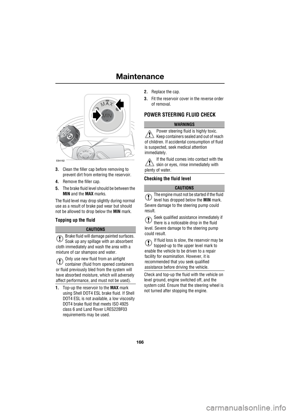
3. Clean the filler cap before removing to
prevent dirt from entering the reservoir.
4. Remove the filler cap.
5. The brake fluid level should be between the
MIN and the MAX marks.
The fluid level may drop slightly during normal
use as a result of brake pad wear but should
not be allowed to drop below the MIN mark.
Topping up the fluid
1.Top-up the reservoir to the MAX mark
using Shell DOT4 ESL brake fluid. If Shell
DOT4 ESL is not availa ble, a low viscosity
DOT4 brake fluid that meets ISO 4925
class 6 and Land Rover LRES22BF03
requirements ma y be used. 2.
Replace the cap.
3. Fit the reservoir cover in the reverse order
of removal.
POWER STEERING FLUID CHECK
Checking the fluid level
Check and top-up the fluid with the vehicle on
level ground, engine switched off, and the
system cold. Ensure that the steering wheel is
not turned after stopping the engine.
CAUTIONS
Brake fluid will damage painted surfaces.
Soak up any spillage with an absorbent
cloth immediately and wash the area with a
mixture of car sh ampoo and water.
Only use new fluid from an airtight
container (fluid from opened containers
or fluid previously bled from the system will
have absorbed moisture, which will adversely
affect performance, and must not be used).
E84162
WARNINGS
Power steering fluid is highly toxic.
Keep containers sealed and out of reach
of children. If accidental consumption of fluid
is suspected, seek medical attention
immediately.
If the fluid comes into contact with the
skin or eyes, rinse immediately with
plenty of water.
CAUTIONS
The engine must not be started if the fluid
level has dropped below the MIN mark.
Severe damage to th e steering pump could
result.
Seek qualified assistance immediately if
there is a noticeable drop in the fluid
level. Severe damage to the steering pump
could result.
If fluid loss is slow, the reservoir may be
topped-up to the uppe r level mark to
enable the vehicle to be driven to a repair
facility for examinatio n. However, it is
recommended that you seek qualified
assistance before driving the vehicle.
Page 2889 of 3229

169
Maintenance
R
TECHNICAL SPECIFICATIONS
Lubricants and fluids
¹ If Shell DOT4 ESL is not available, a low
viscosity DOT4 brake fl uid that meets ISO 4925
class 6 and Land Rover LRES22BF03
requirements may be used. Part Variant Specification
Engine oil Diesel vehicles SAE 5W-30 meeting Ford 913-B specification.
Engine oil Petrol vehicles SA E 0W-30 meeting ACEA A5
or B5 specification.
Main gearbox oil Manual tr ansmission Castrol MTF 97309
Main gearbox oil Automatic transmission Esso JWS3309US
Power transfer unit fluid Die sel vehicles Castrol BOT119
Power transfer unit fluid Petrol vehicles Castrol BOT118
Rear differential oil All vehicles Castrol EPX
Rear differential on demand
coupler fluid All vehicles STAT OIL SL01-301
Power steering fluid All vehicl es Pentosin CHF202 PAS fluid
Brake fluid All vehicles Shell DOT4 ESL ¹
Screen washer All vehicles Screen wash with frost protection
Coolant All vehicles 50% mixture of Texaco XLC antifreeze and water.
Page 2893 of 3229
173
Vehicle battery
R
USING BOOSTER CABLES
Note: Before connecting boos ter cables ensure
that the battery connections on the disabled
vehicle are correct, and that all electrical
equipment has been switched off.
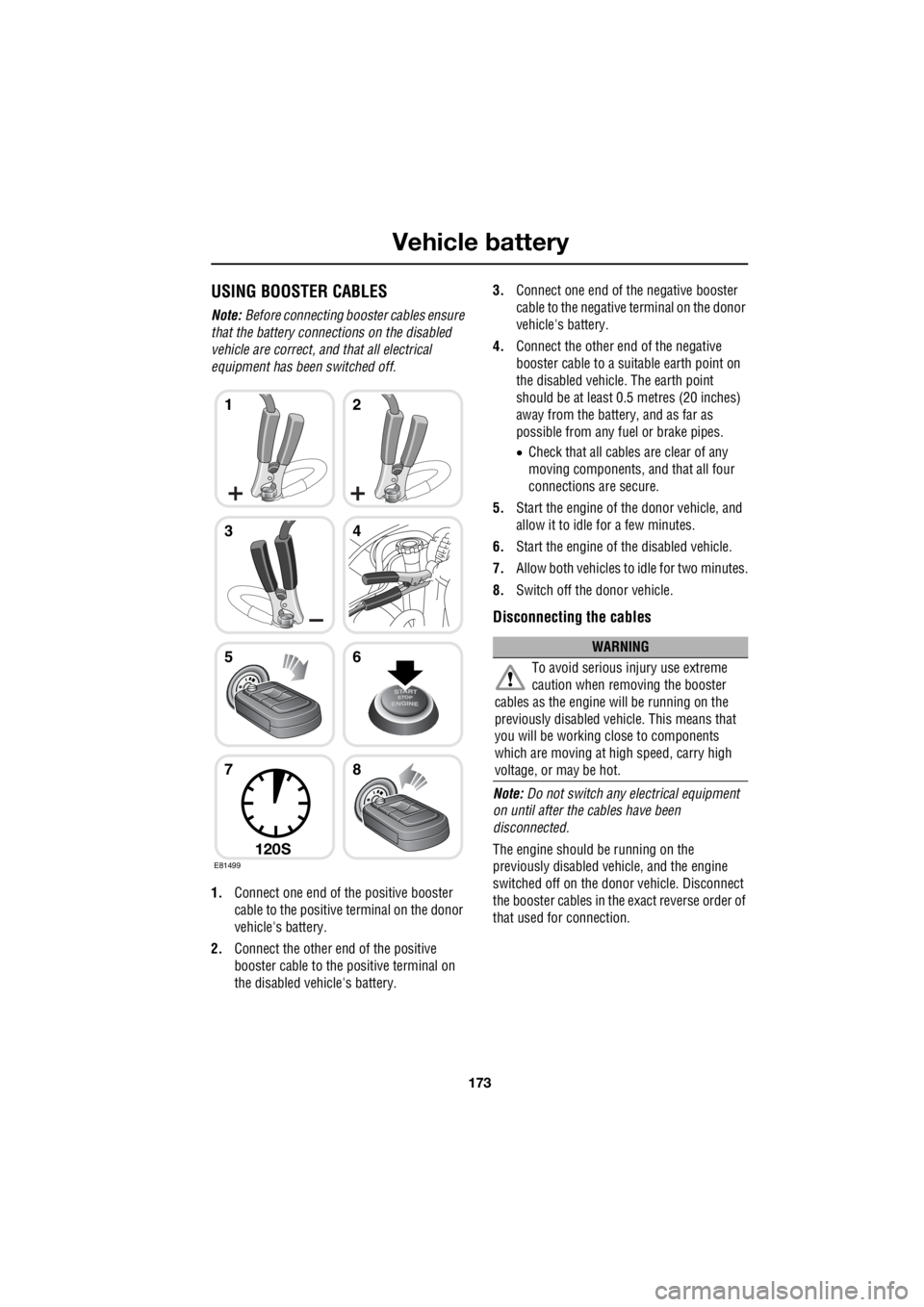
1. Connect one end of the positive booster
cable to the positive terminal on the donor
vehicle's battery.
2. Connect the other e nd of the positive
booster cable to the positive terminal on
the disabled vehicle's battery. 3.
Connect one end of the negative booster
cable to the negative terminal on the donor
vehicle's battery.
4. Connect the other en d of the negative
booster cable to a suit able earth point on
the disabled vehicle. The earth point
should be at least 0.5 metres (20 inches)
away from the battery, and as far as
possible from any fuel or brake pipes.
• Check that all cables are clear of any
moving components, and that all four
connections are secure.
5. Start the engine of the donor vehicle, and
allow it to idle for a few minutes.
6. Start the engine of the disabled vehicle.
7. Allow both vehicles to idle for two minutes.
8. Switch off the donor vehicle.
Disconnecting the cables
Note: Do not switch any electrical equipment
on until after the cables have been
disconnected.
The engine should be running on the
previously disabled ve hicle, and the engine
switched off on the donor vehicle. Disconnect
the booster cables in the exact reverse order of
that used for connection.
E81499
12
34
56
78
120S
WARNING
To avoid serious in jury use extreme
caution when removing the booster
cables as the engine will be running on the
previously disabled vehicle. This means that
you will be working close to components
which are moving at high speed, carry high
voltage, or may be hot.
Page 2899 of 3229
179
Wheels and tyres
R
Tyre checks
Not all punctures result in the tyre deflating
immediately. Therefore, it is important to check
the tyres for damage and foreign objects,
regularly.
When driving, if a sudden vibration, or change
to the vehicle's handling is noticed, reduce
speed immediately. Do not brake hard, or make
any sudden manoeuvres or direction changes.
Drive slowly to an area off of the main highway
and stop the vehicle.
Note: Driving the vehicle to a safe area may
cause damage to the punctured tyre, but
occupant safety is far more important.
Inspect the tyres for signs of punctures,
damage, or under inflat ion. If any damage or
deformity is detected, the tyre should be
replaced. If a spare tyre is not available, then
the vehicle should be recovered to a tyre repair
centre, or Land Rover Dealer/Approved
repairer.
Note: The tyres should be checked
immediately after any off -road use, and prior to
using the vehicle on a public highway.
Replacement tyres
Ideally, tyres should be re placed in sets of four.
If this is not po ssible, replace the tyres in pairs
(front and rear). When tyres are replaced, the
wheels should always be re-balanced, and
alignment checked.
The correct tyre specific ation for your vehicle
can be found on the tyre information label.
WARNINGS
Do not fit cross-ply tyres.
Do not fit tubed tyres.
Do not swap tyres around the vehicle.
Tyres bed in to the specific
characteristics of each wheel position.
Swapping them around may affect the
vehicle's handli ng and traction.
Always fit replacement tyres of the
same type, and wher ever possible of
the same make and tread pattern.
Replacement wheels should be genuine
Land Rover parts. This will maintain the
designed driving charac teristics both on and
off road.
If the use of tyres not recommended by
Land Rover is unavoidable, ensure that
you read, and fully comply with the tyre
manufacturers instructi ons. Failure to do so
may lead to tyre failure due to incorrect fitment
or use.
WARNINGS
Page 2910 of 3229

Wheels and tyres
190
L
Using the Land Rover tyre repair kit
Note: All vehicle drivers and occupants should
be made aware that a temporary repair has
been made to a tyre fitted to the vehicle. They
should also be made aware of the special
driving conditions im posed when using a
repaired tyre. Repair procedure
1. Open the tyre repair kit and peel off the
maximum speed label. Attach the label to
the facia in the driver's field of view. Take
care not to obstruct any of the instruments
or warning lights.
2. Uncoil the compressor power cable and
the inflation hose.
3. Unscrew the orange cap from the sealant
bottle receiver, and the sealant bottle cap.
4. Screw the sealant bottle into the receiver
(clockwise) until tight.
• Screwing the bottle onto the receiver will
pierce the bottle's se al. Do not unscrew
a full, or partly us ed bottle from the
receiver. Doing so will result in the
sealant leaking from the bottle.
5. Remove the valve cap from the damaged
tyre.
6. Remove the protective cap from the
inflation hose, and c onnect the inflation
hose to the tyre valve. Ensure that the hose
is screwed on firmly.
7. Ensure that the compressor switch is in
the off ( O) position.
8. Insert the power cable connector into an
auxiliary power socket. See AUXILIARY
POWER SOCKETS (page 110).
9. Unless the vehicle is in an enclosed or
poorly ventilated area , start the engine.
10. Set the compressor switch to the on ( l)
position.
11. Inflate the tyre to a minimum of 1.8 bar (26
lb/in²) and a maximum of 3.5 bar (51
lb/in²).
†
WARNINGS
Avoid skin contact with the sealant
which contains natu ral rubber latex.
Do not unscrew the sealant bottle from the
receiver until it is empty, as sealant will leak
out.
If the tyre inflation pressure does not
reach 1.8 bar (26 lb/in²) within seven
minutes, the tyre may have suffered excessive
damage. A temporary repair will not be
possible, and the vehicle should not be driven
until the tyre has been replaced.
CAUTIONS
Before attempting a tyre repair, ensure
that the vehicle is parked safely, as far
away from passing traffic as possible.
Ensure that the parki ng brake is applied,
and P is selected if an automatic
transmission is fitted.
Do not attempt to remove foreign objects
such as nails, screws, etc from the tyre.
Always run the engine when using the
compressor, unless the vehicle is in an
enclosed, or poorly ventilated space.
To prevent overheating do not operate
the compressor continuously for longer
than ten minutes.
Page 2913 of 3229

193
Wheels and tyres
R
• Avoid tyre/vehicle damage by removing
the traction devices as soon as the
conditions allow.
TYRE GLOSSARY
Terms used
lbf/in² or psi
Pounds per square inch, an imperial unit of
measure for pressure.
kPa
Kilo Pascal, a metric unit of measure for
pressure.
Cold tyre pressure
The air pressure in a tyre which has been
standing in excess of th ree hours, or driven for
less than one mile.
Maximum inflation pressure
The maximum pressure to which the tyre
should be inflated. This pressure is given on
the tyre side wall in lbf/in² (psi) and kPa.
Note: This pressure is the maximum allowed
by the tyre manufacturer. It is not the pressure
recommended for use. See TECHNICAL
SPECIFICATIONS (page 194).
Kerb weight
The weight of a standa rd vehicle, including a
full tank of fuel, any optional equipment fitted,
and with the correct coolant and oil levels.
Gross vehicle weight
The maximum permissible weight of a vehicle
with driver, passengers, load, luggage,
equipment, and towbar load.
Accessory weight
The combined weight (in excess of those items
replaced) of items available as factory installed
equipment. Production options weight
The combined weight of options installed
which weigh in excess of 1.4 kg (3 lb) more
than the standard items that they replaced, and
are not already considered in kerb or accessory
weights. Items such as heavy duty brakes, high
capacity battery, special trim etc.
Vehicle capacity weight
The number of seats multiplied by 68 kg (150
lb) plus the rated amount of load/luggage.
Maximum loaded vehicle weight
The sum of kerb wei ght, accessory weight,
vehicle capacity weig ht, plus any production
option weights.
Rim
The metal support for a ty re, or tyre and tube,
upon which the tyre beads are seated.
Bead
The inner edge of a tyre th at is shaped to fit to
the rim and form an air tight seal. The bead is
constructed of steel wires which are wrapped,
or reinforced, by the ply cords.