Page 2187 of 3229

Publi s hed: 11-May-2011
Seating - Seats
Diagnosi s and Tes ti ng
Principles of Operation
For a detail ed descripti on of the seat s, refer t o the relevant Descri pti on and Opera t ion s ect ion in t he works hop manual.
REFER to: Seats (501-10 Seati ng, Des cri pti on and Operati on).
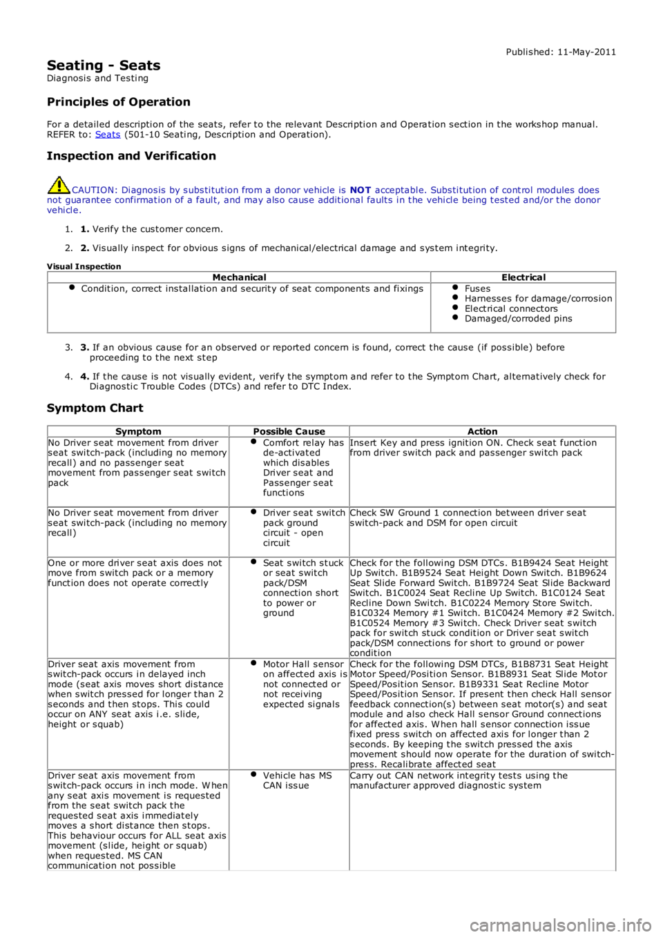
Inspection and Verification CAUTION: Di agnos is by s ubs ti tut ion from a donor vehicle is
NO T acceptabl e. Subs ti tut ion of cont rol modules does
not guarant ee confirmat ion of a faul t, and may als o caus e addit ional fault s i n t he v ehi cl e being t est ed and/or t he donor
vehi cl e.
1. Verify t he cus t omer concern.
1.
2. Vis ually ins pect for obvious s igns of mechani cal /elect rical damage and s ys t em i nt egr i ty.
2.
Visual Inspection Mechanical Electrical
Condit ion, correct ins tal lati on and s ecurit y of seat component s and fi xings Fus es
Harness es for damage/corros ion
El ect ri cal connect ors
Damaged/corroded pins
3.
If an obvious cause for an obs erved or report ed concern is found, correct t he caus e (if pos s ible) before
proceeding t o t he next s t ep
3.
4. If t he caus e is not vis ually evi dent , verify t he sympt om and refer t o t he Sympt om Ch art, al ternat ively check for
Di agnos ti c Trouble Codes (DTCs) and refer t o DTC Index.
4.
Symptom Chart Symptom Possible Cause Action
No Driver s eat movement from driver
s eat swi tch-pack (including no memory
recall ) and no pass enger seat
movement from pas s enger s eat s wi tch
pack Comfort rel ay has
de-acti vat ed
which dis ables
Dri ver s eat and
Pass enger s eat
functi ons Ins ert Key and press ignit ion ON. Check s eat funct ion
from driver swit ch pack and pas senger swi tch pack
No Driver s eat movement from driver
s eat swi tch-pack (including no memory
recall ) Dri ver s eat s wit ch
pack ground
circuit - open
circuit Check SW Ground 1 connect ion bet ween dri ver s eat
s wit ch-pack and DSM for open circuit
One or more dri ver s eat axis does not
move from s wit ch pack or a memory
funct ion does not operat e correct ly Seat s wi tch s t uck
or seat s wit ch
pack/DSM
connecti on short
to power or
ground Check for the foll owi ng DSM DTCs . B1B9424 Seat Height
Up Swit ch. B1B9524 Seat Hei ght Down Swit ch. B1B9624
Seat Sl ide Forward Swit ch. B1B9724 Seat Sl ide Backward
Swit ch. B1C0024 Seat Recli ne Up Swit ch. B1C0124 Seat
Recl ine Down Swi tch. B1C0224 Memory St ore Swi tch.
B1C0324 Memory #1 Swi tch. B1C0424 Memory #2 Swi tch.
B1C0524 Memory #3 Swi tch. Check Driver s eat s wi tch
pack for swit ch st uck condit ion or Driver seat s wit ch
pack/DSM connecti ons for s hort to ground or power
condit ion
Driver seat axis movement from
s wit ch-pack occurs i n delayed inch
mode (s eat axis moves short di s tance
when s wit ch pres s ed for l onger t han 2
s econds and t hen st ops. Thi s coul d
occur on ANY seat axis i .e. s li de,
height or s quab) Motor Hall s ens or
on affect ed axis i s
not connect ed or
not recei ving
expected si gnal s Check for the foll owi ng DSM DTCs , B1B8731 Seat Height
Motor Speed/Posi ti on Sens or. B1B8931 Seat Sl ide Mot or
Speed/Pos it ion Sens or. B1B9331 Seat Recline Motor
Speed/Pos it ion Sens or. If pres ent t hen check Hall s ens or
feedback connect ion(s ) between s eat mot or(s) and s eat
module and al so check Hall s ens or Ground connect ions
for affect ed axis . W hen hall s ens or connect ion i ss ue
fi xed pres s s wit ch on affect ed axi s for l onger t han 2
s econds. By keeping t he s wit ch pres s ed the axis
movement s hould now operate for the durati on of swi tch-
pres s. Recali brate affect ed seat
Driver seat axis movement from
s wit ch-pack occurs i n i nch mode. W hen
any s eat axi s movement i s reques ted
from the s eat s wit ch pack t he
reques ted s eat axis i mmediat el y
moves a s hort di st ance then s t ops .
This behaviour occurs for ALL seat axis
movement (s l ide, hei ght or s quab)
when reques ted. MS CAN
communicati on not pos s ible Vehi cle has MS
CAN i ss ue Carry out CAN network int egrit y t es t s us ing t he
manufacturer approved diagnost ic sys tem
Page 2206 of 3229

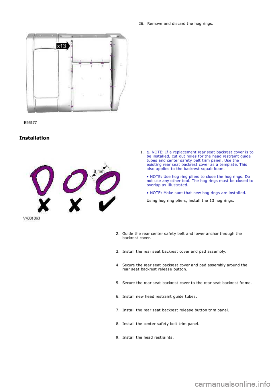
Remove and dis card t he hog rings.26.
Installation
1. NOTE: If a replacement rear seat backres t cover i s t obe ins t al led, cut out holes for the head rest rai nt gui detubes and center s afety bel t trim panel . Us e t heexi s ti ng rear s eat backres t cover as a t emplat e. Thisals o appli es to the backrest squab foam.
• NOTE: Us e hog ring pli ers t o clos e t he hog rings. Donot us e any ot her tool. The hog rings mus t be clos ed t ooverlap as i ll ust rat ed.
• NOTE: Make s ure t hat new hog ri ngs are i nst all ed.
Us ing hog ring pl iers , ins t al l the 13 hog ri ngs .
1.
Guide the rear center s afet y belt and l ower anchor t hrough t hebackrest cover.2.
Inst all t he rear s eat backres t cover and pad ass embly.3.
Secure t he rear s eat backres t cover and pad ass embl y around t herear s eat backres t rel eas e but ton.4.
Secure t he rear s eat backres t cover to the rear seat backrest frame.5.
Inst all new head res t rai nt gui de tubes .6.
Inst all t he rear s eat backres t releas e butt on t ri m panel.7.
Inst all t he cent er safet y belt t rim panel.8.
Inst all t he head res traints .9.
Page 2207 of 3229

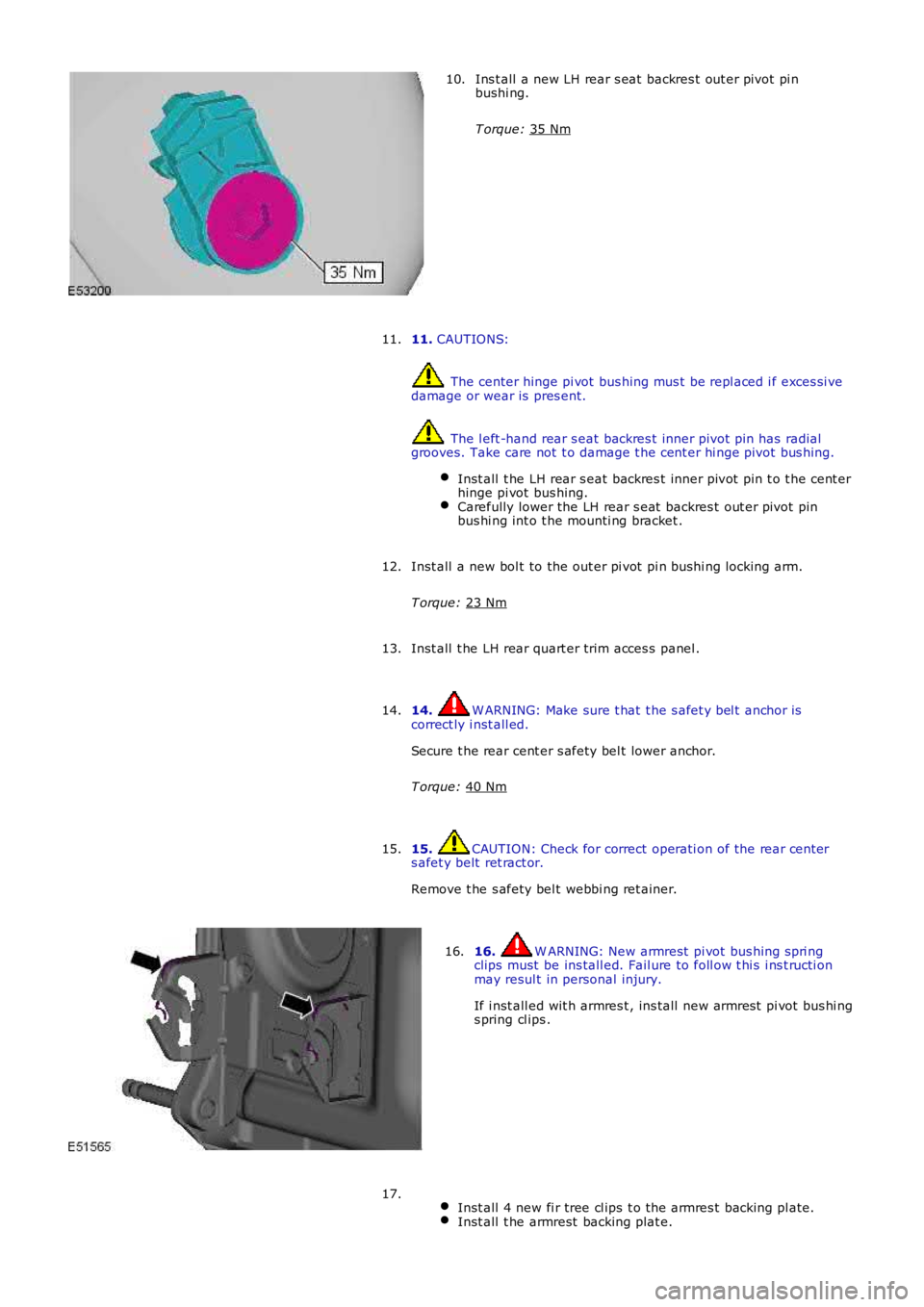
Ins t all a new LH rear s eat backres t out er pivot pi n
bushi ng.
T orque: 35 Nm 10.
11. CAUTIONS: The center hinge pi vot bus hing mus t be repl aced i f exces si ve
damage or wear is pres ent. The l eft -hand rear s eat backres t inner pivot pin has radial
grooves. Take care not t o damage t he cent er hi nge pivot bus hing.
Inst all t he LH rear s eat backres t inner pivot pin t o t he cent er
hinge pi vot bus hing. Carefully lower the LH rear s eat backres t out er pivot pin
bus hi ng int o t he mounti ng bracket . 11.
Inst all a new bol t to the out er pi vot pi n bushi ng locking arm.
T orque: 23 Nm 12.
Inst all t he LH rear quart er trim acces s panel .
13.
14. W ARNING: Make sure t hat t he s afet y bel t anchor is
correct ly i nst all ed.
Secure t he rear cent er s afety bel t lower anchor.
T orque: 40 Nm 14.
15. CAUTION: Check for correct operati on of the rear cent er
s afet y belt ret ract or.
Remove t he s afety bel t webbi ng ret ainer.
15. 16. W ARNING: New armrest pi vot bus hing s pri ng
clips must be ins tall ed. Fail ure to foll ow t hi s i ns t ructi on
may resul t in personal injury.
If i nst all ed wit h armres t , ins tall new armres t pi vot bus hi ng
s pring cl ips .
16.
Inst all 4 new fi r tree cl ips t o t he armres t backing pl ate. Inst all t he armrest backing plat e.17.
Page 2224 of 3229
6. CAUTIONS:
Ti e strapsmust be fitted,fail ure to foll owthis instructionmay resul t inpersonal injury.
Fail ure tofoll ow thisinstructi on maycause damageto the vehicle.
Secure theseat baseusing the 4tie strapssuppli ed, asshown.
Usi ngthe seatheightadjuster,lowerthe seatbase toitslowestpositi on.
7. Rel ease the arm from the height adjuster.
Remove the Torx bolt.
8. Drill out the 4 ri vets.
Installation
1. To instal l, reverse the removal procedure.
Page 2239 of 3229
3.
Installation
To i nst all , revers e t he removal procedure.1.
To s ecure t he door gl ass to t he door glas s mechanis m,l ower t he glas s s quarely t o rest wit hi n t he lat ches .W it h s light pres s ure appli ed t o t op of gl ass as shown,pus h the gl ass down to full y engage.
2.
Page 2240 of 3229
Publi s hed: 11-May-2011
Glass, Frames and Mechanisms - Rear Door Window Glass
Removal and Inst all ati on
Removal
Carefully remove t he outer wais t s eal.1.
If pos s ibl e, l ower the wi ndow glas s byapproximat ely one t hird of it s t ravel.Us ing t he s peci al t ool, rel ease the door windowglas s from the window l ift mechanis m and rais et he glas s t o the top of t he door frame.
2.
Secure t he glas s t o the top of t he frame.3.
Page 2241 of 3229
Lower the wi ndow li ft mechanis m.4.
Lower the door glas s t o the bot tom of the door.Releas e t he li ni ng from bot h guide channel s.
5.
Installation
Inst all t he rear door window glas s .Inst all t he gui de channel li ni ng.Secure t he glas s t o the top of t he frame.
1.
Rais e t he wi ndow li ft mechani s m.2.
Secure t he door wi ndow glas s t o t he window l ift mechanis m.3.
Inst all t he out er wais t s eal and s ecure wi th the Torx s crew.4.
Page 2244 of 3229

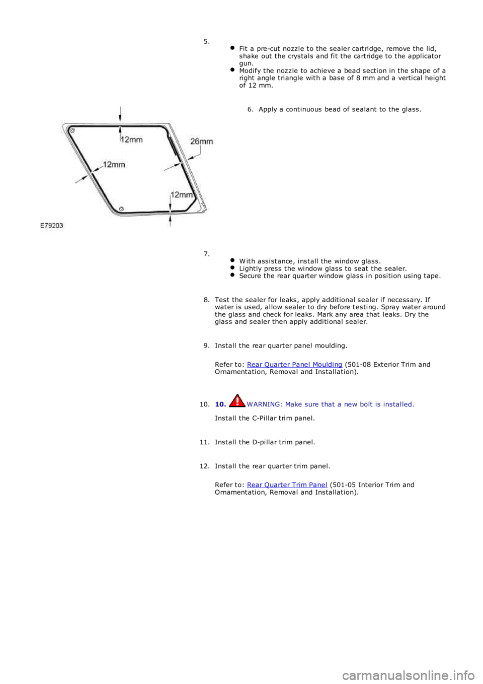
Fit a pre-cut nozzl e t o the sealer cart ri dge, remove the lid,s hake out t he crys tal s and fi t the cartridge t o t he appl icatorgun.Modify t he nozzle to achieve a bead s ecti on in the s hape of aright angl e t ri angle wit h a bas e of 8 mm and a verti cal heightof 12 mm.
5.
Apply a cont inuous bead of s ealant to the gl ass .6.
W it h ass i st ance, i ns t all the window glas s .Light ly pres s t he wi ndow glas s to seat t he s eal er.Secure t he rear quart er window glas s i n posi ti on usi ng t ape.
7.
Tes t the s ealer for l eaks , appl y addit ional s ealer i f necess ary. Ifwat er i s us ed, al low s ealer t o dry before t es ti ng. Spray wat er aroundt he glas s and check for leaks . Mark any area t hat leaks . Dry theglas s and s ealer then apply addi ti onal s eal er.
8.
Inst all t he rear quart er panel moulding.
Refer t o: Rear Quarter Panel Mouldi ng (501-08 Ext eri or Trim andOrnament ati on, Removal and Ins tal lat ion).
9.
10. W ARNING: Make sure t hat a new bolt is ins tal led.
Inst all t he C-Pi llar t ri m panel.
10.
Inst all t he D-pi llar t ri m panel.11.
Inst all t he rear quart er t ri m panel.
Refer t o: Rear Quarter Tri m Panel (501-05 Int erior Tri m andOrnament ati on, Removal and Ins tal lat ion).
12.