2006 LAND ROVER FRELANDER 2 ECU
[x] Cancel search: ECUPage 1988 of 3229
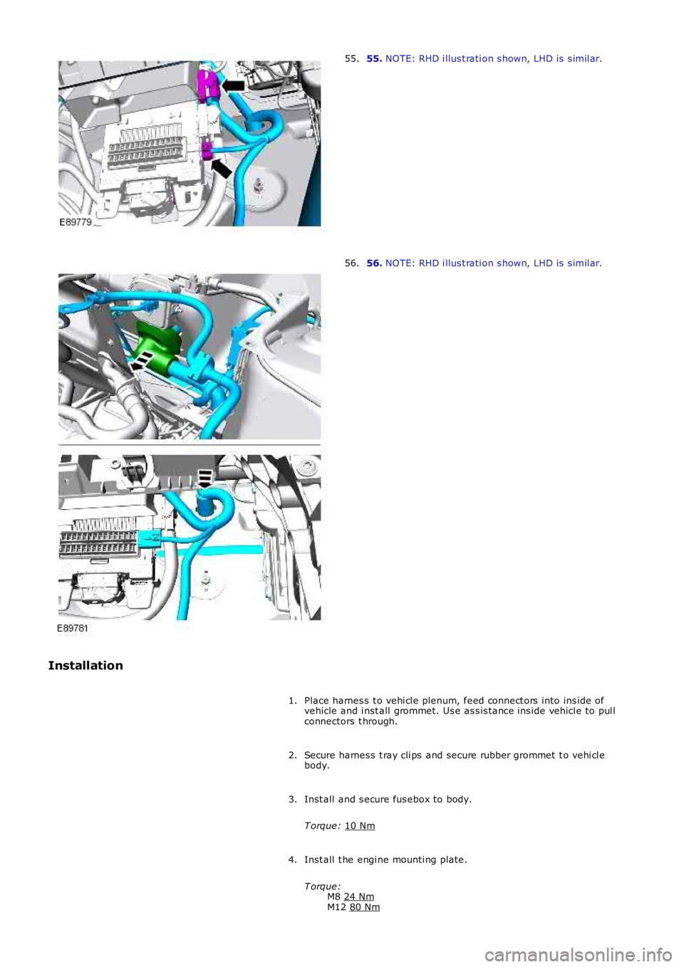
55.
NOTE: RHD i llus t rati on s hown, LHD is s imil ar.
55. 56.
NOTE: RHD i llus t rati on s hown, LHD is s imil ar.
56.
Installation Place harnes s t o vehi cl e plenum, feed connect ors into ins ide of
vehicle and i nst all grommet. Us e as s is tance ins ide vehicl e to pul l
connectors t hrough.
1.
Secure harnes s t ray cli ps and secure rubber grommet t o vehi cl e
body.
2.
Inst all and s ecure fus ebox to body.
T orque: 10 Nm 3.
Inst all t he engi ne mounti ng plate.
T orque: M8 24 Nm M12
80 Nm 4.
Page 1989 of 3229
Secure t he engi ne harnes s to the fus ebox.
5.
Inst all and s ecure t he bat t ery l ead to t he fusebox and ins t al l the
s mall bat tery lead cover.
T orque: 10 Nm 6.
Connect t he two electrical connect ors t o t he BJB.
7.
Secure t he 3 eart h point s and s ecure t he harness cl ips t o t he vehi cl e
body.
T orque: 10 Nm 8.
Secure t he batt ery l ead to the bat tery terminal clamp.
T orque: 25 Nm 9.
Inst all t he fus e box cover.
10.
Inst all t he harness cover to the s us pens ion turret.
11.
Feed harness under t he air cleaner duct and s ecure the duct t o the
grommet.
12.
Secure headl amp and bumper harness cl ips .
13.
Connect t he height sens or elect rical connect or and s ecure t he
harnes s wit h t he cli ps .
14.
Inst all headl amp mount ing plat e.
T orque: 10 Nm 15.
Connect t he s ide repeat er el ect ri cal connector.
16.
Connect t he heat ed was her jet electrical connect ion and s ecure t he
harnes s t o the vehicl e body.
17.
Connect t he ABS s ens or and s ecure t he harness to t he vehicle body.
18.
Secure t he was her pipe to the harnes s and s ecure t he harness to the
body.
19.
Connect t he cras h s ens or electrical connect ors .
20.
Connect t he the bonnet lock electrical connect or
21.
Secure t he harness to the body and t hen secure the bonnet releas e
cabl e t o t he harness .
22.
Secure t he was her pipe to the was her bot tl e.
23.
Inst all t he washer bott le and connect t he elect rical connecti ons .
T orque: 10 Nm 24.
Page 1990 of 3229
Secure t he 3 ground cables t o t he vehi cl e body.
T orque: 10 Nm 25.
Secure t he harness to the vehicle body.
26.
Connect t he the bonnet lock electrical connect or
27.
Inst all t he RH s econdary bul khead mount ing bracket.
T orque: 10 Nm 28.
Inst all t he inner plenum plat e and s ecure t he electrical connect or to
t he plat e.
29.
Connect t he heat ed s creen RH el ect ri cal connector.
30.
Inst all t he auxi liary cool ant pump and connect the feed hos e.
T orque: 10 Nm 31.
Inst all t he FFB heat er coolant feed and ret urn pipes .
32.
Connect t he FFB heat er coolant feed and ret urn hos es to the pi pes .
33.
Connect t he A/C pres sure s wit ch and t he BBUS electrical connect ors .
Als o secure t he harnes s t o t he vehi cl e body.
34.
Secure t he engi ne compartment harnes s t o t he vehi cl e bulkhead.
35.
Secure t he harness tray to the LHS of t he vehicle bul khead.
36.
Connect t he LH heated s creen el ect ri cal connector and s ecure t he
harnes s t o the vehicl e body.
37.
Feed the harnes s i nto the LH wheel arch and s ecure t he grommet.
38.
Inst all t he ABS modulat or bracket.
T orque: 25 Nm 39.
Inst all t he LH s ide repeat er lamp and s ecure t he cli ps to the vehicle
body.
40.
Connect t he rear was her pi pe.
41.
Connect t he ABS s ens or electrical connect or and s ecure the harnes s
t o t he vehi cl e body.
42.
Connect t he two electrical connect ors t o t he CJB.
43.
Connect t he main engi ne compartment harnes s t o t he ins trument
panel harnes s and clos e t he cover.
44.
Connect t he main engi ne compartment harnes s t o t he headl amp
l evell ing ECU.
45.
Connect t he 3 floor harness el ect ri cal connect ions.
46.
Page 2002 of 3229
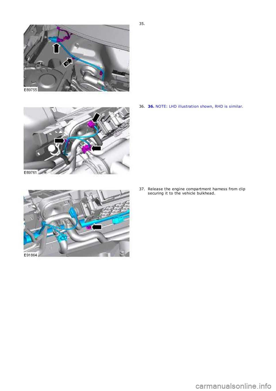
35.
36. NOTE: LHD il lus trati on s hown, RHD is s imil ar.36.
Releas e t he engi ne compartment harnes s from cl ips ecuring i t to the vehicle bul khead.37.
Page 2008 of 3229
52.
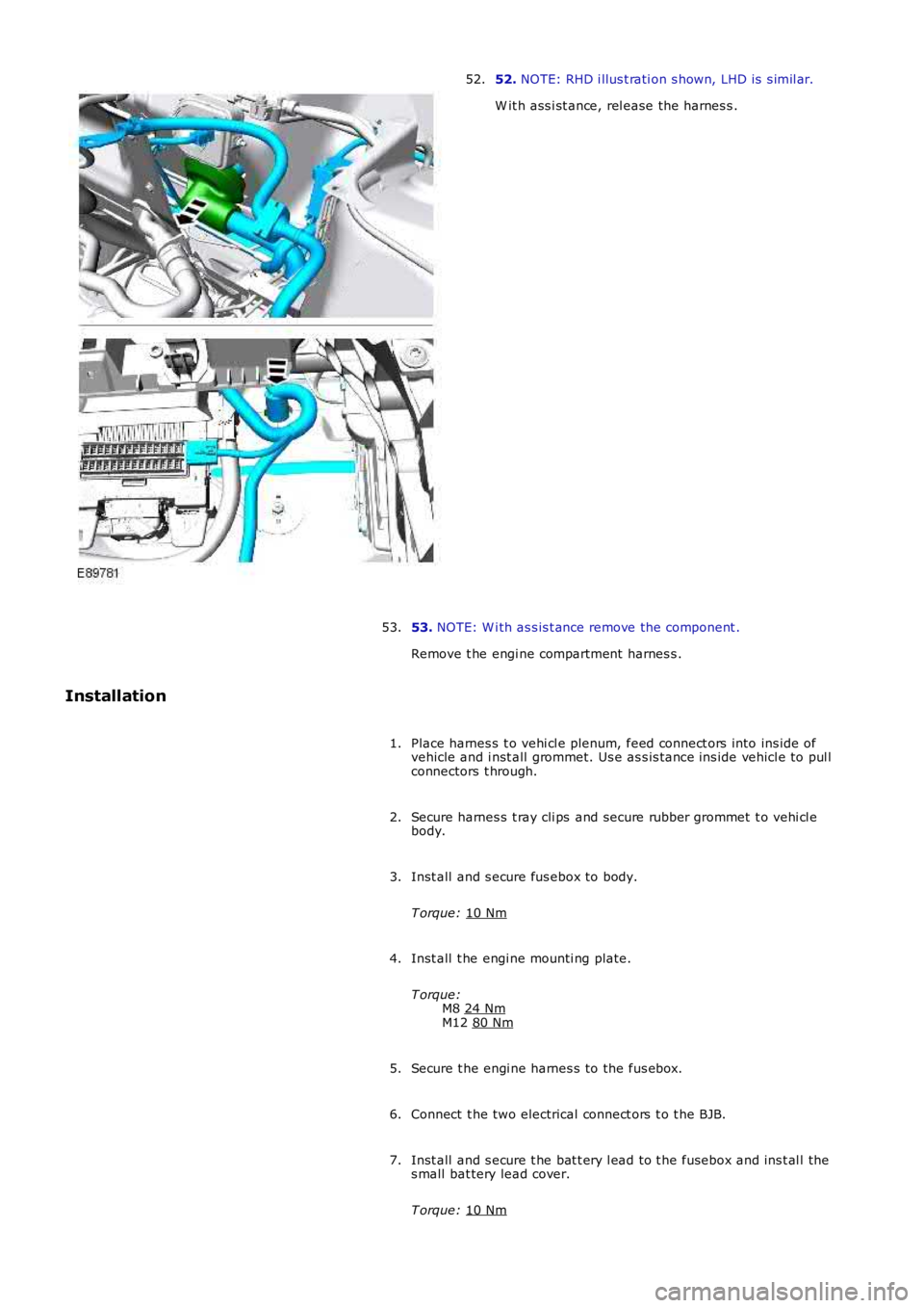
NOTE: RHD i llus t rati on s hown, LHD is s imil ar.
W it h ass i st ance, rel ease the harnes s .
52.
53. NOTE: W i th as s is t ance remove the component .
Remove t he engi ne compartment harnes s .
53.
Installation Place harnes s t o vehi cl e plenum, feed connect ors into ins ide of
vehicle and i nst all grommet. Us e as s is tance ins ide vehicl e to pul l
connectors t hrough.
1.
Secure harnes s t ray cli ps and secure rubber grommet t o vehi cl e
body.
2.
Inst all and s ecure fus ebox to body.
T orque: 10 Nm 3.
Inst all t he engi ne mounti ng plate.
T orque: M8 24 Nm M12
80 Nm 4.
Secure t he engi ne harnes s to the fus ebox.
5.
Connect t he two electrical connect ors t o t he BJB.
6.
Inst all and s ecure t he bat t ery l ead to t he fusebox and ins t al l the
s mall bat tery lead cover.
T orque: 10 Nm 7.
Page 2009 of 3229
Secure t he 3 eart h point s and s ecure t he harness cl ips t o t he vehi cl e
body.
T orque: 10 Nm 8.
Secure t he batt ery l ead to the bat tery terminal clamp.
T orque: 25 Nm 9.
Inst all t he fus e box cover.
10.
Inst all t he harness cover to the s us pens ion turret.
11.
Feed harness under t he air cleaner duct and s ecure the duct t o the
grommet.
12.
Secure headl amp and bumper harness cl ips .
13.
Connect t he height sens or elect rical connect or and s ecure t he
harnes s wit h t he cli ps .
14.
Inst all headl amp mount ing plat e.
T orque: 10 Nm 15.
Connect t he s ide repeat er el ect ri cal connector.
16.
Connect t he heat ed was her jet electrical connect ion and s ecure t he
harnes s t o the vehicl e body.
17.
Connect t he ABS s ens or and s ecure t he harness to t he vehicle body.
18.
Secure t he was her pipe to the harnes s and s ecure t he harness to the
body.
19.
Connect t he cras h s ens or electrical connect ors .
20.
Connect t he the bonnet lock electrical connect or
21.
Secure t he harness to the body and t hen secure the bonnet releas e
cabl e t o t he harness .
22.
Secure t he was her pipe to the was her bot tl e.
23.
Inst all t he washer bott le and connect t he elect rical connecti ons .
T orque: 10 Nm 24.
Secure t he 3 ground cables t o t he vehi cl e body.
T orque: 10 Nm 25.
Secure t he harness to the vehicle body.
26.
Connect t he cool ant l evel s ensor electrical connect or.
27.
Page 2010 of 3229
Inst all t he RH s econdary bul khead mount ing bracket.
T orque: 10 Nm 28.
Inst all t he inner plenum plat e and s ecure t he electrical connect or to
t he plat e.
29.
Connect t he heat ed s creen RH el ect ri cal connector.
30.
Connect t he BBUS electrical connect or.
31.
Connect t he A/C pres sure s wit ch electrical connect or.
32.
Secure t he engi ne compartment harnes s t o t he vehi cl e bulkhead.
33.
Secure t he harness tray to the LHS of t he vehicle bul khead.
34.
Connect t he LH heated s creen el ect ri cal connector and s ecure t he
harnes s t o the vehicl e body.
35.
Feed the harnes s i nto the LH wheel arch and s ecure t he grommet.
36.
Inst all t he ABS modulat or bracket.
T orque: 25 Nm 37.
Inst all t he LH s ide repeat er lamp and s ecure t he cli ps to the vehicle
body.
38.
Connect t he rear was her pi pe.
39.
Connect t he ABS s ens or electrical connect or and s ecure the harnes s
t o t he vehi cl e body.
40.
Connect t he two electrical connect ors t o t he CJB.
41.
Connect t he main engi ne compartment harnes s t o t he ins trument
panel harnes s and clos e t he cover.
42.
Connect t he main engi ne compartment harnes s t o t he headl amp
l evell ing ECU.
43.
Connect t he 3 floor harness el ect ri cal connect ions.
44.
Inst all t he fus e cover and refi t the s ound deadening sheet.
45.
Inst all t he LH fender s pl ash s hi eld.
T orque: 6 Nm 46.
Inst all t he glove compartment l id.
Refer t o: Glove Compart ment (501-12 Ins trument Panel and
Consol e, Removal and Ins t al lat ion).
47.
Inst all t he engi ne upper s upport ins ulat or.
48.
Page 2013 of 3229
Publi s hed: 11-May-2011
Wiring Harnesses - Wiring Harness
Des cript ion and Operat ion
Introduction
CAUTION: Do not us e any ot her heat s hrink s l eeve ot her t han t he approved gl ue li ned heat s hri nk s leeve menti onedin the repai r procedure.
The purpos e of thi s document is to promote qui ck and efficient minor repai r to harnes s connect ors or cabl es usi ngapproved methods and t he wiring harnes s repai r ki t. Repairs may only be made t o cables and connectors which have beenmechani cal ly, not electrically damaged. It al s o appl ies where t he whol e extent of t he damage can be cl early ident ified andrect ifi ed.
Care and neat nes s are es sent ial requirement s i n making a perfect repair.
Caution:
At t he ti me of t his first i s sue of t he Harnes s Repair Guide, do not approve repairs to any of the followi ng circuit s :
Any media orient at ed s yst em trans port net work harnes s es .Suppl ement res traint s ys t em (SRS) firing ci rcuit s (Ai r bags ).Link l ead as s embles , which are unique t o s afety crit ical ci rcuit s s uch as ant i-lock brake s ys tem (ABS) andt hermocouple ci rcuit s . An exampl e of thi s is the ABS wheel s peed sens ors wi th moulded connectors.4. Screened cables , leads and wiring harnes s (s ).
If any harness(s) w ith defective electrical connector terminals or wires from the above circuits are a concern, newcomponents must be installed.
Repair Kit
CAUTION: W here t he repair procedure i ndi cat es t hat a glue l ined heat shrink s leeve shoul d be appli ed, applys ufficient heat t o t he glue l ined heat s hrink t o mel t t he glue i n order to provide a water t ight seal . Do not over heat theglue l ined heat s hrink s l eeve s o t hat the wiri ng harnes s ins ulat ion becomes damaged.
The wiring harnes s repai r kit has been produced whi ch compris es :
Pre-terminat ed wiring harnes s (s ) of different s izes and t ypesThree s izes of butt s pli ce connectorsA s electi on of col ored cable i dent ificati on s leevesTwo s izes of glue l ined heat s hrink s l eevesCri mping pl iersA wi re cut ter and i ns ulat ion s t ri pperAn elect rical connector t ermi nal extract ion handle and ti ps
A s uit able heat s ource, for shrinking heat s hrink sl eeves wi ll be requi red.
The pre-ins ulated di amond gri p range of electrical connect or terminal s and in-line, butt s pli ce connectors cont ai ned wit hint he wiring harnes s repai r ki t are t he only acceptable product for t he repai rs of wi ri ng harness es . The but t connectors notonly grip t he wi re but als o the i nsul at ion, making a very s ecure joi nt.
If an elect rical connect or t erminal is not included i n t he wiring harnes s repai r ki t then approval for t he repair i s NOT gi venand in thes e circums t ances a new wiring harnes s mus t be i ns t alled.
Pre-Terminated Wiring Harness(s) and Butt Splice Connectors
All pre-t ermi nat ed wiring harnes s (s ) and but t spl ice connectors in the wi ri ng harness repair kit are cont ained i n bags whichcan be res ealed after us e. Each bag i s marked wi th the part number of t he it ems s t ored wi thin the bag. Each st oragecompartment i n t he wiring harnes s repai r kit is identi fi ed wit h t he corres pondi ng part number. Make s ure thatpre-terminat ed wiring harnes s (s ) and connectors are not mixed up it is advis abl e t o only open one bag at a ti me and t ores eal the bag s ecurely before opening another bag. Al s o, replace the bag in i ts mati ng part number compartment wi thint he cas e.
The pre-terminat ed wiring harnes s (s ) are suppli ed wit h t he i ns ulat ion i n one of t hree colors , red, blue or yell ow. The col orsdo not appl y t o any part icular ci rcuit but t o t he harness wire s ize. See the Rel at ions hip Table in t he Repair Met hod secti on.
Butt s pli ce connect ors are al so suppli ed wit h red, bl ue or yel low coveri ngs , which mus t be mat ched to the pre-t ermi nat edwiring harnes s i nsul at ion col or.
Pre-Termi nat ed W i ri ng Harnes s(s )