2006 LAND ROVER FRELANDER 2 ECU
[x] Cancel search: ECUPage 1770 of 3229
23-Transmis s ion warni ng indi cat or (low li ne only)
24-Hil l Des cent Cont rol (HDC) fault i ndi cat or (l ow li ne only)
25-Door open i ndi cat or (l ow li ne only)26-Engi ne management s yst em warning i ndicat or (l ow l ine only)
27-Side l amp indicat or
28-Dynami c Stabil it y Control (DSC) indicat or29-HDC acti ve indicator
30-Ant i-t heft alarm i ndi cat or
31-Glow pl ug indicat or (dies el vehicles onl y)32-Fuel fired boos ter heater i ndi cat or (i f fi tt ed)
The low li ne ins trument cl ust er cont ains 39 i ndi cat ors , the hi gh li ne ins t rument clus ter 27. The indicators in hi gh li neins t rument clus ters are s upplemented by mess ages in the mess age cent er.For addit ional informat ion, refer t o: Informat ion and Mes s age Cent er (413-08 Informat ion and Mes s age Cent er, Des cript ionand Operat ion).
The warni ng indicators can be s plit i nto 2 groups ; sel f cont roll ed and ext ernall y cont rol led. Self cont rol led warni ngindicat ors are dependent on software l ogi c wit hin t he i ns t rument clus ter for act ivati on. External ly controll ed indicators ares uppl ied wi th current from anot her s yst em cont roll ing module or ill uminat ed by the ins trument cl us t er on receipt of amedium s peed CAN bus mes sage from the CJB.
Ignition/No Charge Indicator
The ignit ion/no charge indicator i s cont rol led by t he ins t rument clus ter s oft ware and i ll uminated by medium speed CAN buss ignals from the ECM via t he CJB. The indicator il lumi nat es i n a red col or when the vehicle ent ers power mode 6 and isexti nguis hed when t he engine i s s tart ed.
If the i ndi cat or remai ns ill uminat ed aft er the engine has s t art ed or ill uminat es when drivi ng, t he alt ernator charge out puthas fai led.
Low Oil Pressure Warning Indicator
The low oil pres s ure warning i ndi cat or is i lluminated by t he i ns t rument clus ter on recei pt of a medium speed CAN buss ignal from t he CJB. The s ignal ori gi nates i n t he ECM and is generat ed by t he engi ne oil l evel s ens or on petrol vehicl es andt he engi ne oil pres s ure s ensor on di esel vehi cles .
The indicat or i ll uminates i n a red color when t he vehi cl e enters power mode 6 for a 3 s econd bulb check. If t he bul bs ubs equent ly ill uminat es when the engine is runni ng, t he engine s houl d be s t opped i mmediat ely i t is s afe to do s o.
Malfunction Indicator Lamp
The Malfunct ion Indicat or Lamp (MIL) i s il lumi nat ed by t he ins trument cl ust er on receipt of a medi um s peed CAN bus s ignalfrom the CJB. The si gnal originat es in t he ECM and i s generated if an On-Board Diagnos ti c (OBD) fault has been det ectedwhich wi ll caus e excess i ve emis s ions output. Thi s may rel ate to ei ther an engine management or trans mi ss i on fault .
The MIL is ill uminat ed in an amber color when t he vehi cl e enters power mode 6 for a 3 s econd bul b check. The bul b checkin thi s ins tance is carri ed out by the ECM vi a t he CJB, not t he ins trument cl ust er. If t he MIL subs equent ly i lluminates t hevehi cl e s houl d be i nterrogated us ing t he Land Rover approved diagnost ic sys tem at the earli es t opport uni ty.
Safety Belt Warning Indicator
The s afety bel t warni ng indicator wi ll il lumi nat e i n a red color on receipt of a medi um s peed CAN bus s ignal from t he CJB.The s ignal origi nat es in the Res traint s Cont rol Module (RCM), which monit ors the s t at us of t he occupant clas s ificati ons ys t em and s wi tches located i n t he s afety bel t buckles .
Three vari ati ons of warning are avai lable depending on vehicle confi gurati on:
Reminder (al l vehicl es except Nort h Ameri can Specificati on (NAS) vehicles )Federal Mot or Vehi cl e Safet y Standard (FMVSS) 208 remi nder (NAS vehi cles only)Belt Mi nder
The condi ti ons for s afety bel t warning indicator il lumi nat ion are as follows :
Reminder
Vehicle i n power mode 6Dri vers s afet y belt not s ecured in i ts buckleLarge pas senger det ect ed i n front pas s enger s eat wit h an uns ecured safety bel t.
The warni ng indicator wi ll remai n i lluminated unt il eit her t he i gni ti on is swi tched off or condi ti ons 2 and 3 no longer exis t .
FMVSS-208 Reminder
Vehicle i n power mode 6Dri vers s afet y belt not s ecured in i ts buckle.
The warni ng indicator wi ll remai n i lluminated for 65 s econds and wil l be accompanied by a si ngl e 6 second chi me from theins t rument clus ter s ounder.
• NOTE: The warni ng indicator and chime wil l not acti vat e i f thes e condi ti ons aris e 75 seconds aft er t he vehicle hasentered power mode 6.
The warni ng indicator wi ll be exti ngui shed and t he s ounder cancell ed if t he i gni ti on is s wi tched off or t he dri ver's s afet ybelt i s s ecured in i ts buckle.
Belt Mi nder
Page 1771 of 3229
Vehicle i n power mode 6 (all vehi cles except NAS vehicles )Vehicle i n power mode 6 for 75 s econds (NAS vehicl es onl y)Vehicle s peed is greater t han 6 mph (10 kph)Dri vers s afet y belt not s ecured in i ts buckleLarge pas senger det ect ed i n front pas s enger s eat wit h an uns ecured safety bel t.
The warni ng indicator wi ll flas h at a frequency of 2 Hz while accompani ed by a chime from the i nst rument clus ter for 10s econds. Thi s is foll owed by a 10 s econd period where the warning i ndicat or is permanent ly ill uminat ed and the s ounder i ss il ent . Thi s 10 s econd cycle wi ll be repeat ed for a maxi mum of 190 seconds or any of t he condit ions l is t ed above cease toexis t.
Supplemental Restraint System Warning Indicator
The Suppl ement al Rest rai nt Sys tem (SRS) warning i ndi cat or is i lluminated on recei pt of a medium s peed CAN bus si gnalfrom the CJB. The si gnal originat es in t he RCM whi ch monit ors t he condi ti on of the SRS and ill uminat es the red warni ngindicat or accordingly.
The SRS warni ng indicator i s il lumi nat ed by t he RCM for a 6 s econd bul b check when the vehicle firs t ent ers power mode 6.If a fault is detect ed wit h t he indicator, the ins trument cl us t er returns a medi um speed CAN bus s ignal vi a t he CJB to theRCM and a Diagnos t ic Troubl e Code (DTC) i s s tored in the RCM's memory. The mes s age 'SrS' wi ll als o be di spl ayed i n t heodometer.For addit ional informat ion, refer t o: Informat ion and Mes s age Cent er (413-08 Informat ion and Mes s age Cent er, Des cript ionand Operat ion).
Left and Right Hand Turn Signal Indicators
The green l eft and right hand turn s ignal i ndicat ors are i ll uminated on recei pt of medium speed CAN bus s i gnals from t heCJB. The CJB provi des a CAN bus s ignal wit h one of t he foll owing values :
0 - LH st eeri ng col umn mul ti -funct ion s wit ch in the central pos it ion1 - LH st eeri ng col umn mul ti -funct ion s wit ch in the LH turn posi ti on2 - LH st eeri ng col umn mul ti -funct ion s wit ch in the RH turn pos it ion3 - Hazard fl as hers reques t ed.
If the vehicle is i n power mode 6 t he ins trument cl ust er wil l fl as h the appropri ate turn s ignal i ndicat or if a medium speedCAN bus s ignal is recei ved wit h a value of 1 or 2. Medi um s peed CAN bus s ignals wi th a value of 3 wi ll acti vat e both theLH and RH turn s ignal i ndicat ors si mult aneous ly i rrespecti ve of power mode.
W hen acti vat ed, the l eft and right hand turn s ignal indicators wil l be accompanied by 'ti ck t ock' chimes from t he ins trumentclus ter s ounder.
Brake Warning Indicator
EBA and EBD warnings are trans mi tt ed t o t he CJB from t he ABS module over t he high s peed CAN bus . Thes e s ignals arerel ayed t o t he i ns t rument clus ter on t he medium s peed CAN bus and wil l act ivate the brake warning i ndicat or when t hevehi cl e i s in power mode 6. If an EBA warni ng is request ed, the i ndi cat or wil l ill uminat e in an amber color. If an EBDwarni ng is reques t ed, t he indi cat or will i ll uminate in a red color.
Low brake flui d level warnings are als o t rans mit t ed to the i nst rument clus t er from the CJB on the medi um s peed CAN bus .The s ignal origi nat es in the ABS modul e which recei ves a hardwired input from the brake flui d level s ens or. If a l ow brakefl uid warning i s reques ted, the indicator wil l il lumi nat e i n a red col or when the vehicle is i n power mode 6.
The brake warni ng indi cat or i s als o s ubject t o a 3 second bul b check when the vehicle firs t ent ers power mode 6. Theindicat or wi ll i lluminate in a amber color for 1.5 s econds t hen a red col or for 1.5 s econds .
High Eng ine Coolant Temperature Warning Ind icator
The red hi gh Engine Coolant Temperature (ECT) warning i ndi cat or is control led by the engine t emperat ure gage s oft ware(see above).
Headlamp High Beam Indicator
The blue headlamp hi gh beam i ndi cat or is i ll uminated on recei pt of a medium s peed CAN bus si gnal from the CJB. Thes ignal origi nat es in the l ight s wit ch module and i s t ransmit ted t o t he CJB over t he LIN bus. The i nst rument clus t er will onlyil lumi nat e t he headl amp high beam indicator when t he vehicle i s in power mode 6 and t he LH s teeri ng column mul ti -functi on s wit ch is moved t o t he high beam pos i ti on.
Tire Pressure Monitoring System Indicator
The Tire Pres s ure Moni tori ng Syst em (TPMS) indicator i s cont rol led by t he ins t rument clus ter on receipt of medium s peedCAN bus s ignals from t he CJB. The s ignal ori gi nates i n t he TPMS module. The indicator i s il lumi nat ed in an amber col or fora 3 second bulb check by the TPMS modul e when t he vehi cl e enters power mode 6. If t he indicator remains i lluminated orfl ashes after t he engi ne is st art ed or when dri vi ng, the TPMS has developed a faul t. The t ire pres s ures s houl d bemonit ored manuall y unti l the fault is recti fi ed.For addit ional informat ion, refer t o: W heels and Ti res (204-04 W heels and Tires , Des cript ion and Operat ion).
Anti-lock Brake System Warning Indicator
The Anti -l ock Brake Sys t em (ABS) warning i ndicat or is controll ed by the ABS module whi ch trans mi ts a high s peed CAN busmes s age to t he CJB. The CJB relays t he mes sage t o t he i ns t rument clus ter over the medi um s peed CAN bus . The warningindicat or i s il lumi nat ed i n an amber col or for 3 s econds for a bulb check by the ABS modul e when t he vehi cl e enters powermode 6. If the warning i ndi cat or remains ill uminat ed or ill uminat es when drivi ng, an ABS fault has occurred and t he ABSfuncti on wil l not be avai lable.
Duri ng the bul b check, if t he warni ng indicator comes on for 0.5 s econd, t hen goes off for 0.5 second and is then
Page 1777 of 3229
Us ing t hese inputs t he ECM us es an al gorit hm t o moni tor t he driver’s t orque and performance demand in the current geart o est abli sh if t he s ame t orque and performance coul d be achi eved in t he next hi ghest gear to improve fuel effi ci ency,wit hout introduci ng engi ne labori ng.
The s ignal from t he Steeri ng Angle Sens or i s us ed to inhibi t ill uminat ion of t he Gear Shi ft Indi cat or when the vehicle ist ravel ing round a bend in the road.
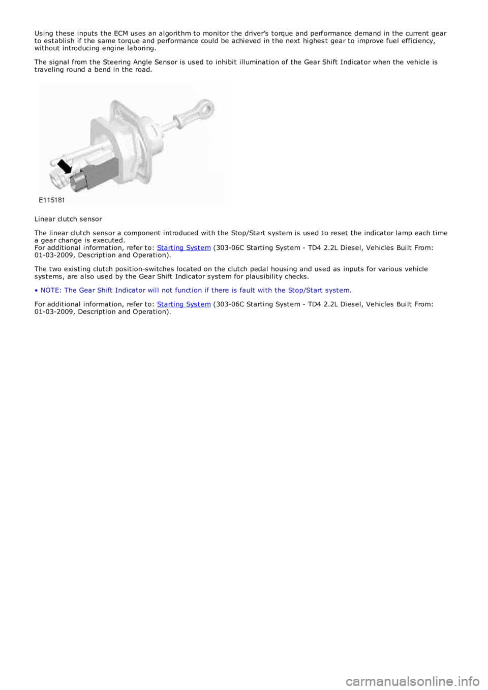
Linear cl utch s ensor
The li near clut ch s ens or a component i nt roduced wit h t he Stop/St art s ys tem is us ed to reset t he indicat or l amp each ti mea gear change i s executed.For addit ional informat ion, refer t o: Starti ng Sys t em (303-06C Starti ng Syst em - TD4 2.2L Di es el, Vehicles Bui lt From:01-03-2009, Descripti on and Operat ion).
The t wo exis ti ng clutch pos it ion-s wi tches located on the clut ch pedal housi ng and used as inputs for various vehicles ys t ems , are al so us ed by t he Gear Shift Indicator s yst em for plaus ibil it y checks.
• NOTE: The Gear Shi ft Indicator wil l not funct ion if t here is fault wi th the St op/St art s yst em.
For addit ional informat ion, refer t o: Starti ng Sys t em (303-06C Starti ng Syst em - TD4 2.2L Di es el, Vehicles Bui lt From:01-03-2009, Descripti on and Operat ion).
Page 1783 of 3229
Publi s hed: 11-May-2011
Horn - Horn
Des cript ion and Operat ion
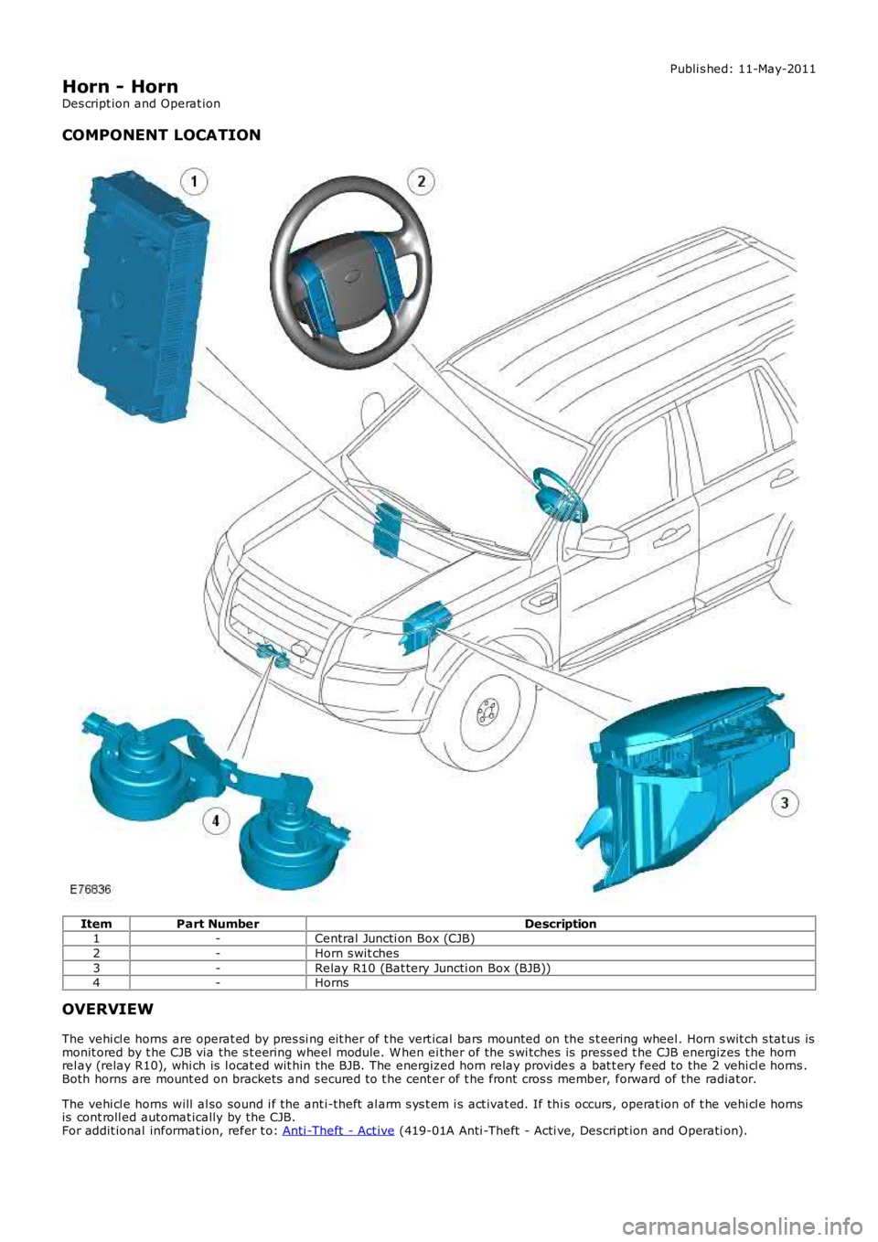
COMPONENT LOCATION
ItemPart NumberDescription1-Central Juncti on Box (CJB)
2-Horn s wit ches
3-Relay R10 (Bat tery Juncti on Box (BJB))4-Horns
OVERVIEW
The vehi cl e horns are operat ed by pres si ng eit her of t he vert ical bars mounted on the s t eering wheel . Horn s wit ch s tat us ismonit ored by t he CJB via the s t eering wheel module. W hen ei ther of the s wi tches is press ed t he CJB energizes t he hornrel ay (relay R10), whi ch is l ocat ed wit hin the BJB. The energized horn relay provi des a bat t ery feed to the 2 vehi cl e horns .Both horns are mount ed on brackets and s ecured t o t he cent er of t he front cros s member, forward of the radiat or.
The vehi cl e horns will al so sound i f the ant i-theft al arm s ys t em i s act ivat ed. If thi s occurs , operat ion of t he vehi cl e hornsis cont roll ed automat ically by the CJB.For addit ional informat ion, refer t o: Anti -Theft - Act ive (419-01A Anti -Theft - Acti ve, Des cri pt ion and Operati on).
Page 1789 of 3229
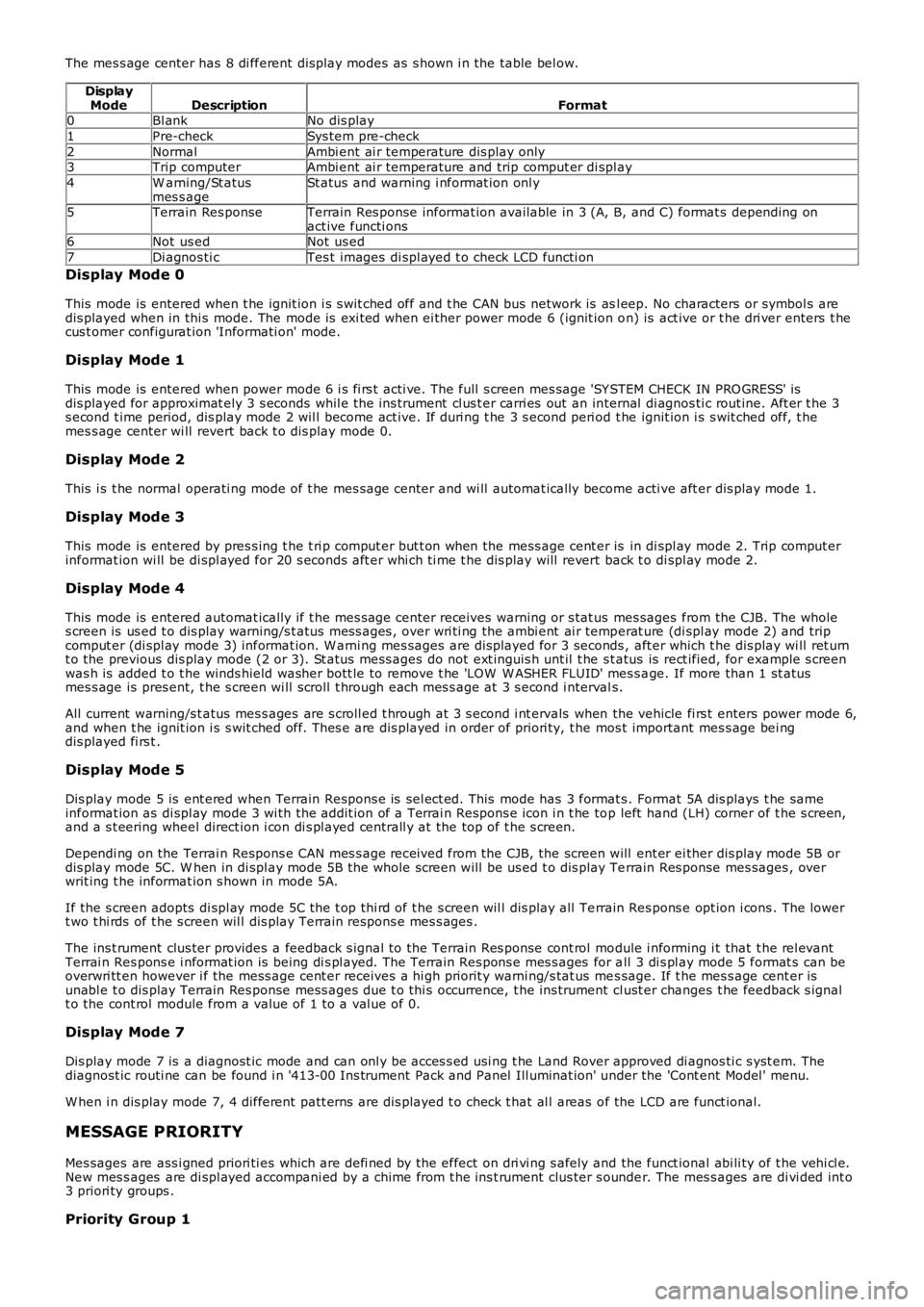
The mes s age center has 8 di fferent dis play modes as s hown i n the table bel ow.
DisplayModeDescriptionFormat0Bl ankNo dis play
1Pre-checkSys tem pre-check
2NormalAmbi ent ai r temperature dis play only3Trip computerAmbi ent ai r temperature and trip comput er di spl ay
4W arning/St atusmes s ageSt atus and warning i nformat ion onl y
5Terrain Res ponseTerrain Res ponse informat ion available in 3 (A, B, and C) format s depending onact ive functi ons6Not us edNot us ed
7Di agnos ti cTes t images di spl ayed t o check LCD functi on
Display Mode 0
This mode is entered when t he ignit ion i s s wit ched off and t he CAN bus network is asl eep. No characters or symbol s aredis played when in thi s mode. The mode is exi ted when ei ther power mode 6 (ignit ion on) is act ive or t he dri ver enters t hecus t omer configurat ion 'Informati on' mode.
Display Mode 1
This mode is entered when power mode 6 i s fi rs t acti ve. The full s creen mes sage 'SY STEM CHECK IN PRO GRESS' isdis played for approximat ely 3 s econds whil e the ins trument cl us t er carri es out an internal di agnos ti c rout ine. Aft er t he 3s econd t ime period, dis play mode 2 wil l become act ive. If duri ng t he 3 s econd peri od t he ignit ion i s s wit ched off, t hemes s age center wi ll revert back t o dis play mode 0.
Display Mode 2
This i s t he normal operati ng mode of t he mes sage center and wi ll automat ically become acti ve aft er dis play mode 1.
Display Mode 3
This mode is entered by pres s ing t he t ri p comput er but t on when the mess age cent er is in di spl ay mode 2. Trip comput erinformat ion wi ll be di spl ayed for 20 s econds aft er whi ch ti me t he dis play will revert back t o di spl ay mode 2.
Display Mode 4
This mode is entered automat ically if t he mes sage center receives warning or s tat us mes sages from the CJB. The wholes creen is us ed t o dis play warning/s t atus mes s ages , over wri ti ng the ambi ent ai r temperat ure (di spl ay mode 2) and tripcomput er (di spl ay mode 3) informat ion. W arni ng mes sages are dis played for 3 seconds , aft er which t he dis play wi ll ret urnt o the previous dis play mode (2 or 3). St atus mess ages do not ext inguis h unt il t he st atus is rect ified, for example s creenwas h is added t o t he winds hield washer bott le to remove t he 'LOW W ASHER FLUID' mes s age. If more than 1 st atusmes s age is pres ent, t he s creen wi ll s croll t hrough each mes s age at 3 s econd i ntervals.
All current warning/s t atus mes s ages are s croll ed t hrough at 3 s econd i nt ervals when the vehicle fi rs t enters power mode 6,and when t he ignit ion i s s wit ched off. Thes e are dis played in order of priori ty, t he mos t important mes s age bei ngdis played fi rs t .
Display Mode 5
Dis play mode 5 is ent ered when Terrain Respons e is sel ect ed. This mode has 3 format s. Format 5A dis plays t he sameinformat ion as di spl ay mode 3 wi th the addit ion of a Terrai n Respons e icon i n t he top left hand (LH) corner of t he s creen,and a s t eering wheel direct ion i con di s pl ayed centrall y at the top of t he s creen.
Dependi ng on the Terrai n Respons e CAN mes s age received from the CJB, the screen will ent er ei ther dis play mode 5B ordis play mode 5C. W hen in di spl ay mode 5B t he whole screen will be us ed t o dis play Terrain Res ponse mes sages , overwrit ing t he informat ion s hown in mode 5A.
If the s creen adopts di spl ay mode 5C t he t op thi rd of t he s creen wil l dis play all Terrain Res pons e opt ion i cons . The lowert wo t hi rds of t he s creen wil l dis play Terrain respons e mes s ages .
The ins t rument clus ter provides a feedback s ignal to the Terrain Res ponse cont rol module i nforming i t that t he rel evantTerrai n Res pons e i nformat ion is being di s pl ayed. The Terrain Res pons e mes s ages for all 3 di s pl ay mode 5 format s can beoverwri tt en however i f the mess age cent er receives a hi gh priorit y warni ng/s tat us mes sage. If t he mes s age cent er isunabl e t o dis play Terrain Res ponse mess ages due t o thi s occurrence, t he ins trument cl ust er changes t he feedback s ignalt o the cont rol module from a value of 1 to a val ue of 0.
Display Mode 7
Dis play mode 7 is a diagnost ic mode and can onl y be acces s ed usi ng t he Land Rover approved di agnos ti c s yst em. Thediagnost ic routi ne can be found i n '413-00 Ins trument Pack and Panel Ill uminat ion' under the 'Cont ent Model ' menu.
W hen i n dis play mode 7, 4 different patt erns are dis played t o check t hat al l areas of the LCD are funct ional.
MESSAGE PRIORITY
Mes sages are ass i gned priori ti es which are defi ned by the effect on dri vi ng s afely and the funct ional abi li ty of t he vehi cl e.New mes s ages are di spl ayed accompani ed by a chime from t he ins t rument clus ter s ounder. The mes s ages are di vi ded int o3 priori ty groups .
Priority Group 1
Page 1814 of 3229

Due t o t he high depth of di scharge a deal er demons trati on vehi cl e batt ery may experience, bat teri es t hat are fi tt ed t ovehi cl es us ed as deal er demons trati on vehi cl es mus t be connected t o a power s upply / charger capable of deli vering 50Amps or more whil st the vehicle is being demons trated and t he engine i s not running. Thi s wi ll prevent the bat tery frombeing damaged from "energy t hroughput " wear out during a demons t rat ion.
Software Reflash, SDD work or Ig nition On related Workshop Activities.
Due t o t he high elect rical current demand and high dept h of Dis charge that can occur duri ng vehi cl e s oft ware re-flas hact ivi ti es , SDD work or igni ti on on rel at ed work in the workshop, vehi cl es that are undergoi ng s uch act ivit ies MUST havet he elect rical s ys tem on t he vehi cl e s upported wi th a power supply / charger / vehicle maintai ner capabl e of deliveri ng 50Amps or more.
Jump Starting New vehicles Before They Have Been Delivered to the Customer.
It is t he dealer / ret ailers res ponsi bili ty to ens ure the bat tery is not al lowed t o go flat by fol lowi ng the i nst ruct ionsand process es defi ned in this manual .However i f ci rcums tances dictat e t hat a new vehi cl e mus t be jump s t arted due to a flat bat t ery whil s t the vehicle isin the dealer / retail ers care, t he batt ery on this vehi cl e mus t be repl aced wi th a new one prior to del ivery to thecus t omer at the dealer / retail ers l iabil it y.The vehi cl e s houl d als o undergo inves t igati on as t o why t he batt ery went flat.Do not connect the jump s t art ing cable t o t he negat ive (-) terminal of the bat tery. Al ways connect t o t herecommended eart hing point . As defined i n t he owners handbook or s ervice document ation for t hat vehi cl e.
Jump Starting or Boost Charging Vehicles in Service
Do not connect the jump s t art ing cable t o t he negat ive (-) terminal of the bat tery. Al ways connect t o t he recommendedeart hing point . As defined i n t he owners handbook or s ervice document ati on for t hat vehi cl e.
Charging AG M Batteries
AGM bat teries mus t not be charged wit h volt ages above 14.8 Vol ts . Doing so wil l damage t hem.
Testing AGM Batteries
Midt ronics 393, 394, 493 and 494 t es ters are not capabl e of tes ti ng AGM bat teries . Doing s o can give an incorrect res ult .
W hen i t is necess ary to tes t an AGM bat tery us e t he Midt ronics EXP1080 tes ter or t he GR1 Diagnost ics Charger.
3. EQUIPMENT (MINIMUM STANDARD) (pictures are for illustration only)
Tracti on Batt ery Charger (or si mil ar st and-alone charger)
Midt ronics EXP1080 Hand-Held Tes ter
Page 1820 of 3229
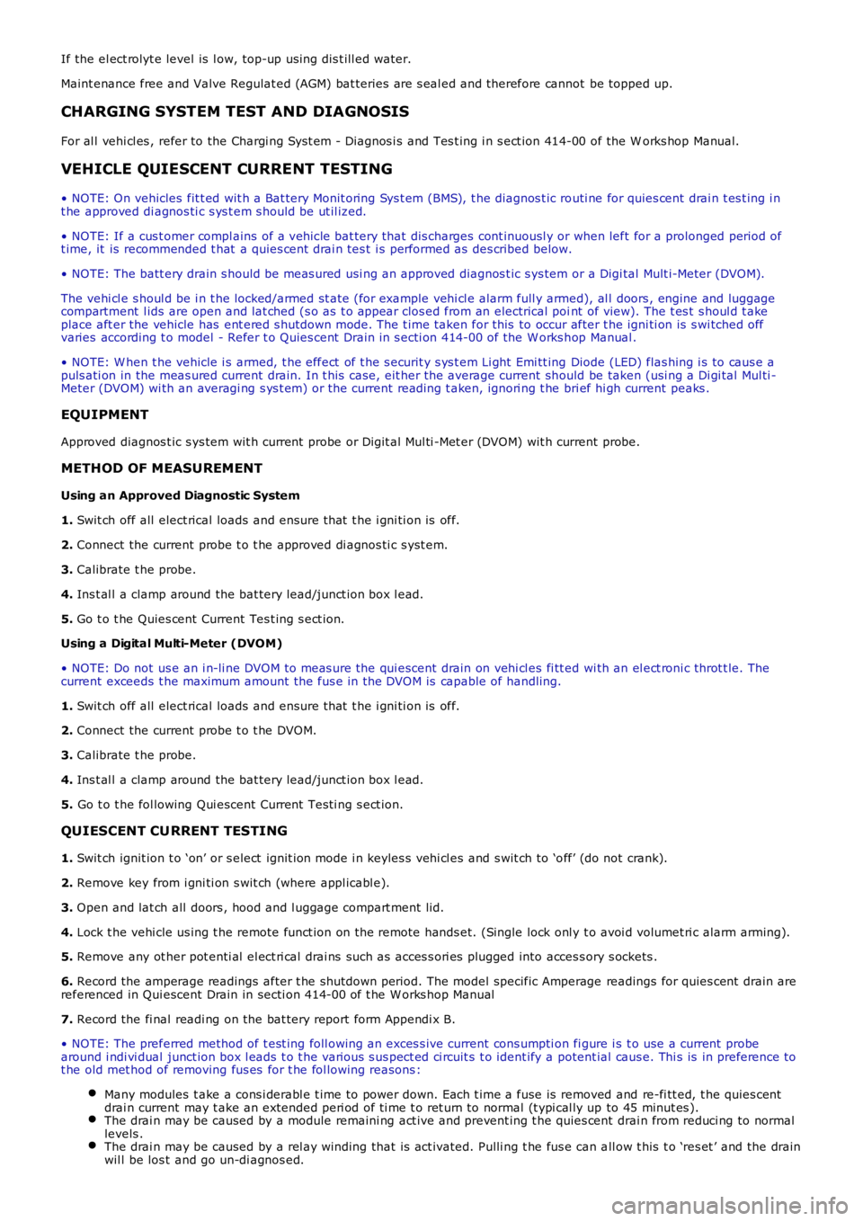
If the el ect rolyt e level is l ow, top-up usi ng dis t ill ed water.
Maint enance free and Valve Regulat ed (AGM) bat teries are s eal ed and therefore cannot be topped up.
CHARGING SYSTEM TEST AND DIAGNOSIS
For al l vehi cl es , refer to the Chargi ng Syst em - Diagnos i s and Tes t ing i n s ect ion 414-00 of the W orks hop Manual.
VEHICLE QUIESCENT CURRENT TESTING
• NOTE: On vehicles fit t ed wit h a Bat tery Monit oring Sys t em (BMS), t he diagnos t ic routi ne for quies cent drai n t es t ing i nt he approved di agnos ti c s ys t em s hould be ut il ized.
• NOTE: If a cus t omer compl ains of a vehicle bat tery that dis charges cont inuousl y or when left for a prolonged period oft ime, it is recommended t hat a quies cent drai n tes t i s performed as des cribed below.
• NOTE: The batt ery drain s hould be meas ured usi ng an approved diagnos t ic s ys tem or a Digi tal Mult i-Meter (DVOM).
The vehi cl e s houl d be i n t he locked/armed st ate (for example vehi cl e alarm full y armed), al l doors , engine and luggagecompartment l ids are open and lat ched (s o as t o appear clos ed from an electrical point of view). The t es t s houl d t akeplace aft er the vehicle has ent ered s hutdown mode. The t ime taken for this to occur after t he igni ti on is s wi tched offvaries according t o model - Refer t o Quies cent Drain in s ecti on 414-00 of the W orks hop Manual .
• NOTE: W hen t he vehicle i s armed, t he effect of t he s ecurit y s ys t em Li ght Emi tt ing Diode (LED) flas hing i s to caus e apuls ati on in the meas ured current drain. In t hi s case, eit her the average current should be taken (usi ng a Di gi tal Mul ti -Meter (DVOM) wi th an averagi ng s ys t em) or the current reading t aken, ignori ng t he bri ef hi gh current peaks .
EQUIPMENT
Approved diagnos t ic s ys tem wit h current probe or Digit al Mul ti -Met er (DVOM) wit h current probe.
METHOD OF MEASUREMENT
Using an Approved Diagnostic System
1. Swit ch off all elect rical loads and ensure t hat t he i gni ti on is off.
2. Connect the current probe t o t he approved di agnos ti c s yst em.
3. Calibrate t he probe.
4. Ins t al l a clamp around the bat tery lead/junct ion box l ead.
5. Go t o t he Quies cent Current Tes t ing s ect ion.
Using a Digital Multi-Meter (DVOM)
• NOTE: Do not us e an i n-li ne DVOM to meas ure the qui escent drain on vehi cl es fi tt ed wi th an el ect roni c throt t le. Thecurrent exceeds t he maximum amount the fus e in the DVOM is capable of handling.
1. Swit ch off all elect rical loads and ensure t hat t he i gni ti on is off.
2. Connect the current probe t o t he DVOM.
3. Calibrate t he probe.
4. Ins t al l a clamp around the bat tery lead/junct ion box l ead.
5. Go t o t he fol lowing Qui escent Current Tes ti ng s ect ion.
QUIESCENT CU RRENT TESTING
1. Swit ch ignit ion t o ‘on’ or s elect ignit ion mode i n keyles s vehi cl es and s wit ch to ‘off’ (do not crank).
2. Remove key from i gni ti on s wit ch (where appl icabl e).
3. Open and lat ch all doors , hood and l uggage compart ment li d.
4. Lock t he vehi cle us ing t he remote funct ion on the remote hands et. (Single lock onl y t o avoi d volumet ri c alarm arming).
5. Remove any ot her pot enti al el ect ri cal drai ns such as acces s ori es plugged into acces sory s ockets .
6. Record the amperage readings after t he shut down period. The model specific Amperage readings for quies cent drain arereferenced in Qui escent Drain in secti on 414-00 of t he W orks hop Manual
7. Record the fi nal readi ng on the bat tery report form Appendi x B.
• NOTE: The preferred method of t est ing foll owing an exces s ive current cons umpti on fi gure i s t o use a current probearound i ndi vi dual junct ion box l eads t o t he various s us pect ed ci rcuit s t o ident ify a potent ial caus e. Thi s is in preference t ot he old met hod of removing fus es for t he fol lowing reasons :
Many modules t ake a cons i derabl e t ime to power down. Each t ime a fuse is removed and re-fi tt ed, t he quies centdrai n current may t ake an extended peri od of ti me t o ret urn to normal (t ypi cal ly up to 45 minut es ).The drai n may be caused by a module remaini ng act ive and prevent ing t he quies cent drai n from reduci ng to normallevels .The drai n may be caused by a rel ay winding that is act ivated. Pulli ng t he fus e can all ow t his t o ‘res et ’ and the drainwil l be los t and go un-di agnos ed.
Page 1824 of 3229
Publ is hed: 05-Dec-2011
Battery and Charging System - General Information - Charging System
Diagnosi s and Tes ti ng
Principles of Operation
For a detail ed descripti on of the chargi ng s ys t em, refer t o t he rel evant Des cript ion and Operat ion secti on in the workshopmanual. REFER to:
Bat t ery Care (414-00, Des cript ion and Operat ion),Bat t ery and Cables (414-01, Des cri pti on and Operati on),Generator - ID4 2.4L Di esel (414-02, Des cri pt ion and Operati on).
Inspection and Verification
CAUTION: Di agnos is by s ubs ti tut ion from a donor vehicle is NO T acceptabl e. Subs ti tut ion of cont rol modules doesnot guarant ee confirmat ion of a faul t, and may als o caus e addit ional fault s i n t he vehi cl e being t est ed and/or t he donorvehi cl e.
1. Verify t he cus t omer concern.1.
2. Vis ually ins pect for obvious s igns of mechani cal or electrical damage.2.
• NOTE: Check the vehicle bat tery condi ti on and st ate of charge before condemning any of the chargi ng s ys t emcomponents . For addi ti onal i nformat ion, refer to the bat tery care manual.
For a compl ete lis t of all di agnos ti c troubl e codes that coul d be l ogged on t his vehicle, pleas e refer to s ect ion 100-00.REFER to: (100-00)
Diagnos t ic Troubl e Code (DTC) Index - DTC: Engine Cont rol Module (PCM) (Des cri pt ion and Operati on),Diagnos t ic Troubl e Code (DTC) Index - DTC: Ins trument Clus ter (IPC) (Des cri pti on and Operati on).
Visual Inspection
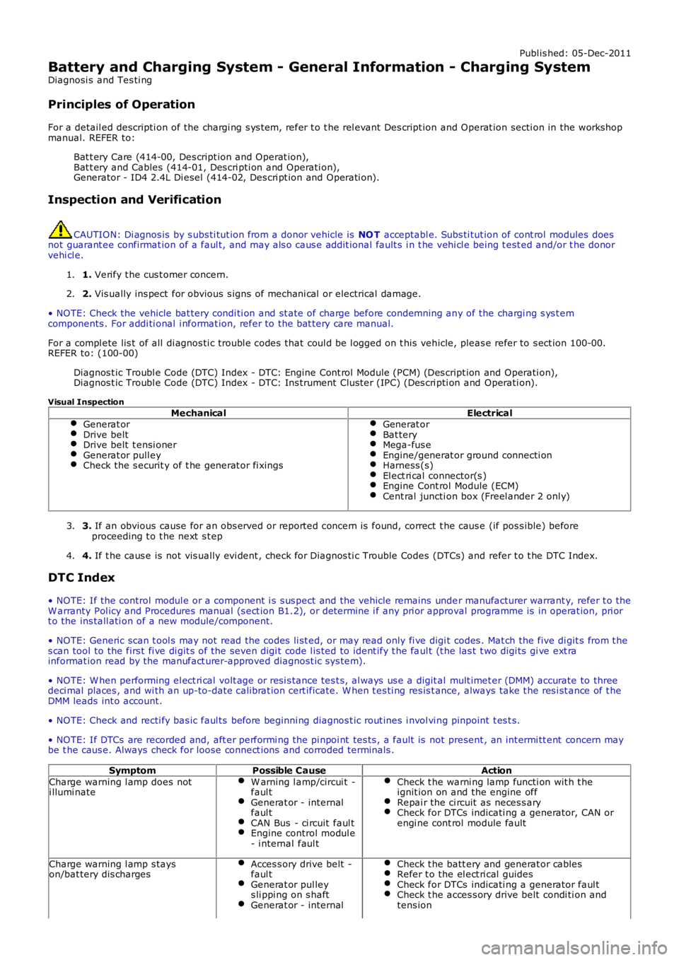
MechanicalElectricalGenerat orDrive beltDrive belt t ensi onerGenerat or pull eyCheck the s ecurit y of t he generat or fi xings
Generat orBat teryMega-fus eEngine/generat or ground connecti onHarness (s)El ect ri cal connector(s )Engine Cont rol Module (ECM)Cent ral juncti on box (Freel ander 2 onl y)
3. If an obvious cause for an obs erved or report ed concern is found, correct t he caus e (if pos s ible) beforeproceeding t o t he next s t ep3.
4. If t he caus e is not vis ually evi dent , check for Di agnos ti c Trouble Codes (DTCs) and refer t o t he DTC Index.4.
DTC Index
• NOTE: If the control modul e or a component i s s us pect and the vehicle remains under manufacturer warrant y, refer t o theW arranty Pol icy and Procedures manual (s ect ion B1.2), or determine i f any pri or approval programme is in operat ion, pri ort o the ins tall ati on of a new module/component.
• NOTE: Generic scan t ool s may not read the codes li st ed, or may read only fi ve digit codes . Mat ch the five di git s from t hes can tool to the firs t fi ve di git s of the seven digi t code l is ted to ident ify t he faul t (t he las t t wo digi ts gi ve ext rainformat ion read by the manufact urer-approved diagnost ic s ys tem).
• NOTE: W hen performing el ect ri cal volt age or resi s tance tes t s, al ways us e a digit al mult imet er (DMM) accurate to threedeci mal places , and wi th an up-to-date cali brat ion cert ificate. W hen t es ti ng res is t ance, always take t he res i st ance of t heDMM leads int o account.
• NOTE: Check and recti fy bas ic faul ts before beginni ng diagnos t ic rout ines i nvol vi ng pinpoint t es t s.
• NOTE: If DTCs are recorded and, aft er performi ng the pi npoi nt tes ts , a fault is not present , an int ermi tt ent concern maybe t he caus e. Always check for loose connect ions and corroded terminals .
SymptomPossible CauseAction
Charge warning l amp does noti llumi nateW arning l amp/circui t -faul tGenerat or - internalfaul tCAN Bus - ci rcuit faul tEngine control modul e- i nternal faul t
Check t he warni ng lamp functi on wit h t heignit ion on and the engine offRepai r the ci rcuit as neces s aryCheck for DTCs indicati ng a generator, CAN orengi ne cont rol module fault
Charge warning l amp s tayson/bat tery dis chargesAcces s ory drive belt -faul tGenerat or pul leys li ppi ng on s haftGenerat or - internal
Check t he batt ery and generat or cablesRefer t o the el ect ri cal guidesCheck for DTCs indicati ng a generator faul tCheck t he acces s ory drive belt condi ti on andtens ion