2006 LAND ROVER FRELANDER 2 ECU
[x] Cancel search: ECUPage 1477 of 3229
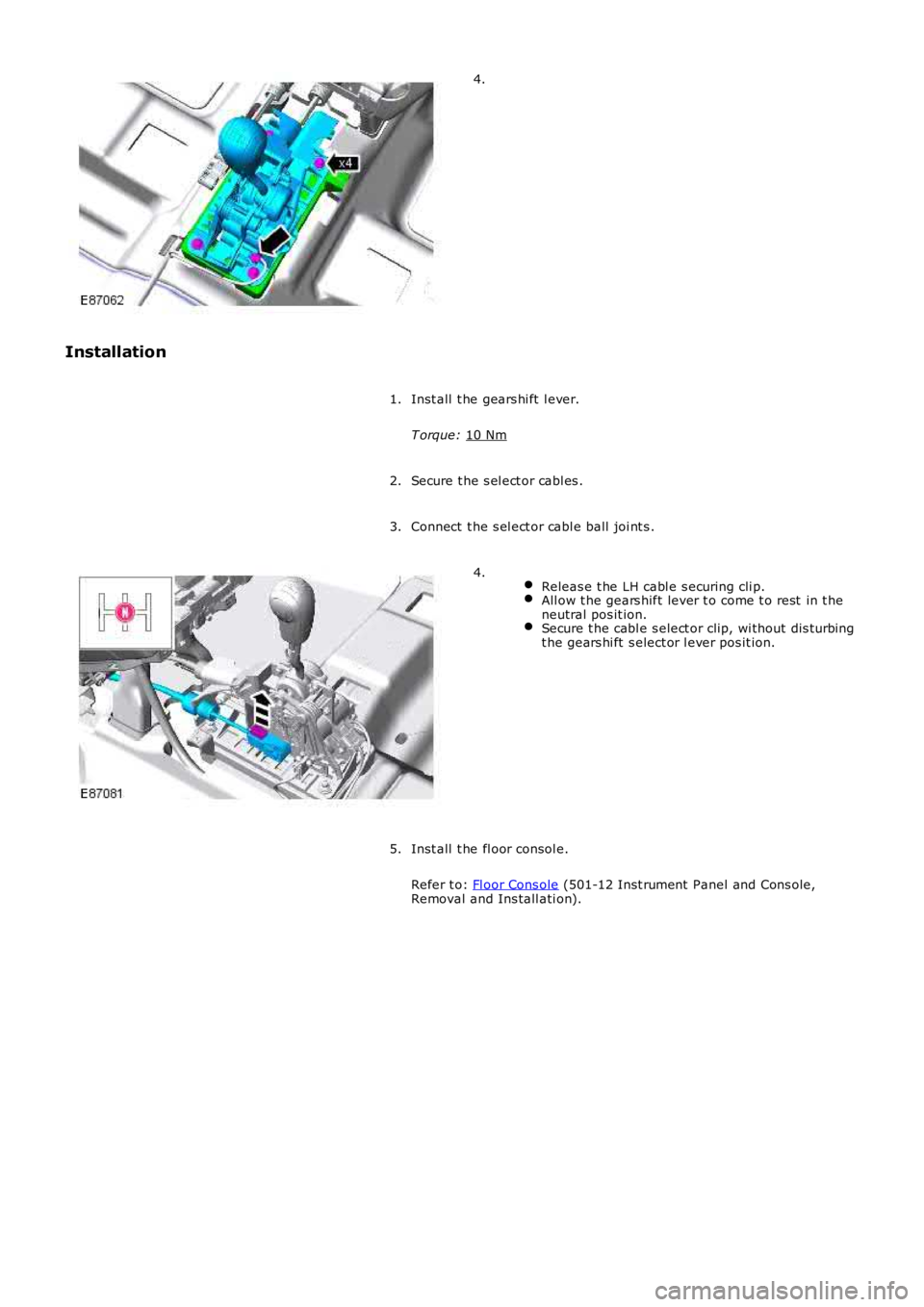
4.
Installation Inst all t he gears hi ft l ever.
T orque: 10 Nm 1.
Secure t he s el ect or cabl es .
2.
Connect t he s el ect or cabl e ball joi nt s .
3.
Releas e t he LH cabl e s ecuring cli p. All ow t he gears hift lever t o come t o rest in t he
neutral pos it ion. Secure t he cabl e s elect or clip, wi thout dis turbing
t he gears hi ft s elect or l ever pos it ion. 4.
Inst all t he fl oor consol e.
Refer t o: Fl oor Cons ole (501-12 Inst rument Panel and Cons ole,
Removal and Ins tall ati on).
5.
Page 1482 of 3229
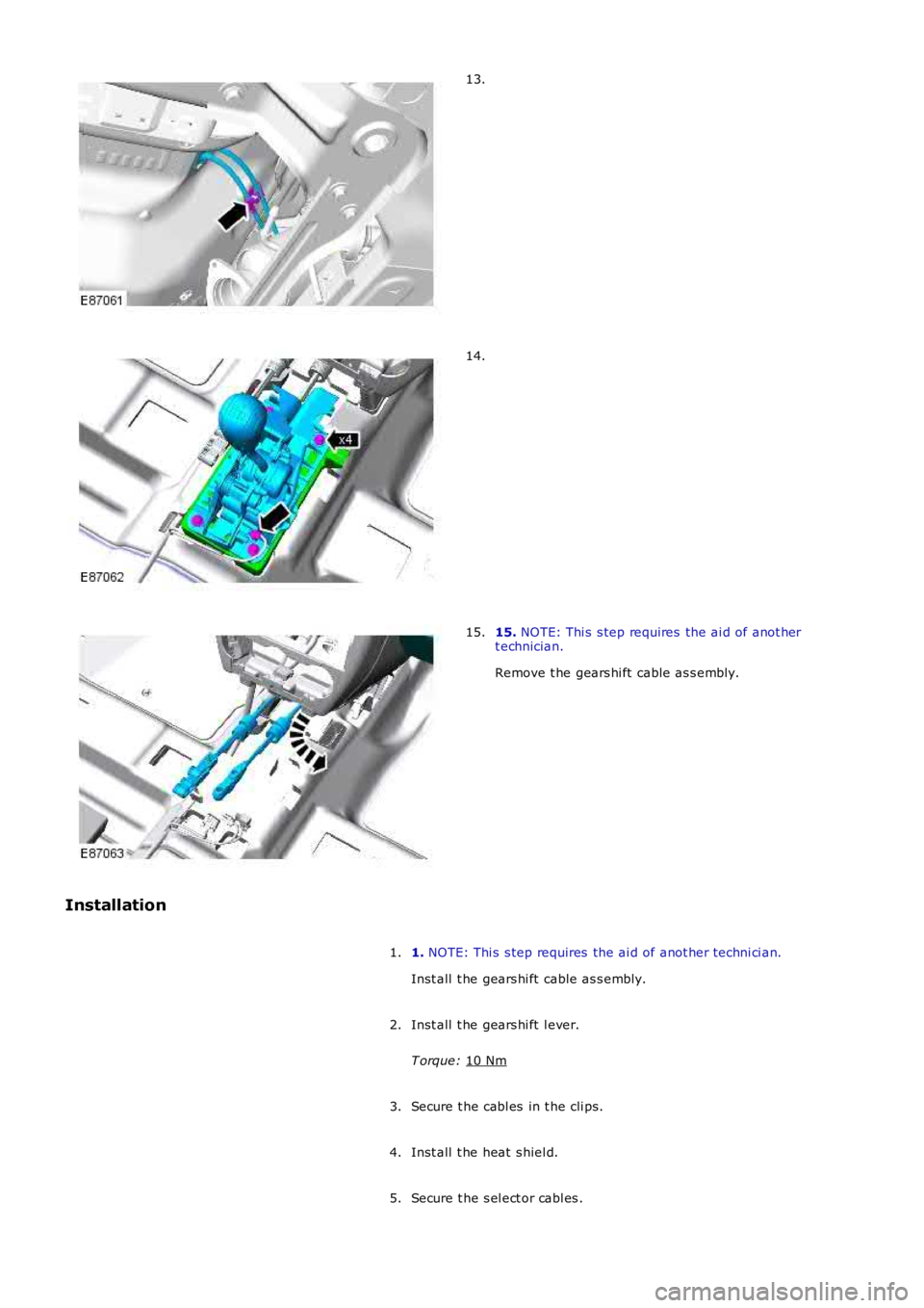
13.
14.
15.
NOTE: Thi s s tep requires the ai d of anot her
t echnician.
Remove t he gears hi ft cable as s embly.
15.
Installation 1. NOTE: Thi s s tep requires the ai d of anot her techni ci an.
Inst all t he gears hi ft cable as s embly.
1.
Inst all t he gears hi ft l ever.
T orque: 10 Nm 2.
Secure t he cabl es in t he cli ps.
3.
Inst all t he heat s hiel d.
4.
Secure t he s el ect or cabl es .
5.
Page 1483 of 3229
Inst all t he s eal ing plat e.
T orque: 7 Nm 6.
Connect t he s el ect or cabl e ball joi nt s .
7.
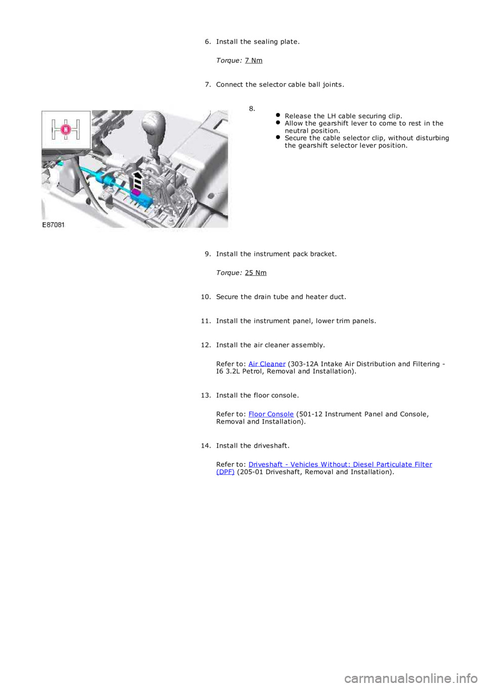
Releas e t he LH cabl e s ecuring cli p. All ow t he gears hift lever t o come t o rest in t he
neutral pos it ion. Secure t he cabl e s elect or clip, wi thout dis turbing
t he gears hi ft s elect or l ever pos it ion. 8.
Inst all t he ins trument pack bracket.
T orque: 25 Nm 9.
Secure t he drain tube and heater duct.
10.
Inst all t he ins trument panel, l ower trim panel s.
11.
Inst all t he air cleaner as s embly.
Refer t o: Air Cleaner (303-12A Intake Ai r Dis tribut ion and Fil tering -
I6 3.2L Pet rol, Removal and Ins t al lat ion).
12.
Inst all t he fl oor consol e.
Refer t o: Fl oor Cons ole (501-12 Inst rument Panel and Cons ole,
Removal and Ins tall ati on).
13.
Inst all t he dri ves haft .
Refer t o: Dri ves haft - Vehicles W it hout : Dies el Part icul ate Fi lt er (DPF) (205-01 Driveshaft, Removal and Ins tal lati on).
14.
Page 1487 of 3229

t he power t rans fer unit .
The crown wheel is support ed in the cas ing on opposi ng t aper rol ler beari ngs whi ch are press ed i nto t he casi ng and t hehous i ng. The drive gear is retained i n t he cas i ng by a housi ng which i s bolt ed to the cas ing and s ealed wi th an O ring seal.The hous i ng is fit t ed wit h a t riple edge oi l seal and fl inger on the out er end of the hous ing which di rect dirt and mois tureaway from the area of the drive gear. Another s eal i s fit ted whi ch prevent s t he ingres s of dirt and mois t ure bet ween thedri ve gear and t he RH hal f shaft .
The pinion gear i s located i n t he hous ing at 90 degrees to the crown wheel drive gear. The pini on gear i s s upport ed i n t hecas i ng on oppos ing taper roll er bearings . The pi nion gear is retai ned in t he housi ng wit h a pre-l oad nut . The outer end oft he pinion gear is spl ined and mat es wit h t he dri ve shaft out put fl ange. The fl ange is s ecured wi th a fl anged bol t which iss crewed int o t he pinion gear.
A coll aps i bl e s pacer is locat ed between the out er t aper roll er beari ng and a s houlder on the pi nion gear. The coll aps ibl es pacer holds t he bearing i n ali gnment and al so col laps es under pres s ure appli ed to the pre-l oad nut . This all ows t hepre-load nut to be t ightened t o a predet ermi ned torque, which coll aps es t he s pacer, s et ti ng the correct bearing pre-loadand t he correct mes hi ng of the pi nion gear and crown wheel drive gear t eet h.
Dri ve from the t rans mis s ion di fferenti al drives t he crown wheel dri ve gear, which in turn rot ates t he pini on gear. Dri ve ispass ed from the pi nion gear to the drive s haft and t he rear different ial via the drive flange att ached to t he pini on gears haft.
Page 1515 of 3229
5-Gasket
6-Tailpi pe fi nis her (opti onal )
7-Mount ing rubber (6 off)8-Rear muffler
9-Cent re muffler
10-Flange11-Bracket
12-Catalyt ic converter (2 off)
13-Flange14-Catalyt ic converter (2 off)
15-Exhaus t manifol d gas ket s
OVERVIEW
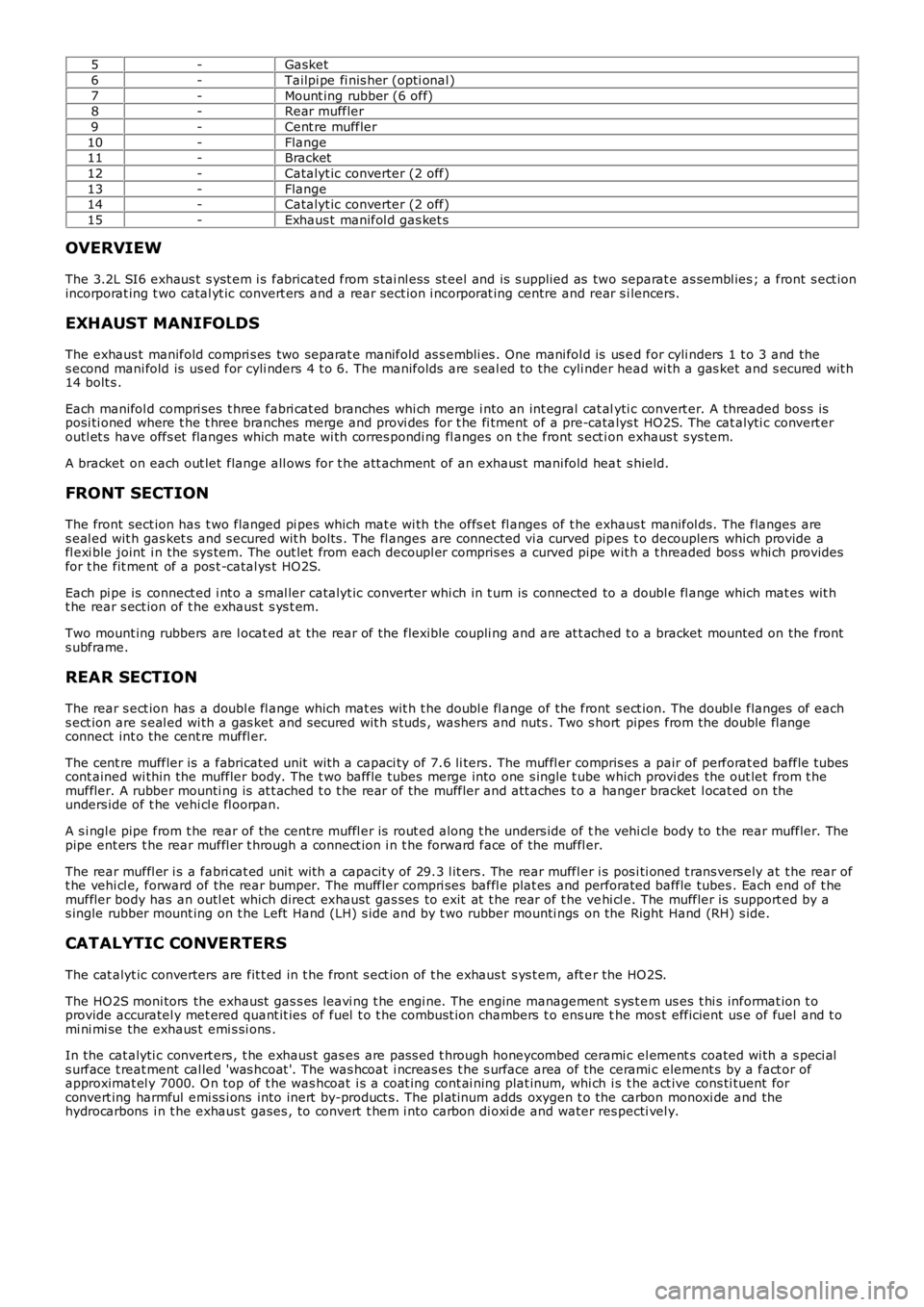
The 3.2L SI6 exhaus t s yst em i s fabricated from s tai nl ess st eel and is s upplied as two separat e as sembl ies ; a front s ect ionincorporat ing t wo catal yt ic convert ers and a rear sect ion i ncorporat ing centre and rear s i lencers.
EXHAUST MANIFOLDS
The exhaus t manifold compri s es two separat e manifold as s embli es . One mani fol d is us ed for cyli nders 1 t o 3 and thes econd mani fold is us ed for cyli nders 4 t o 6. The manifolds are s eal ed to the cyli nder head wi th a gas ket and s ecured wit h14 bolt s .
Each manifol d compri ses t hree fabri cat ed branches whi ch merge i nto an int egral cat alyti c convert er. A threaded bos s isposi ti oned where t he t hree branches merge and provi des for t he fi tment of a pre-catalys t HO2S. The cat alyti c convert eroutl et s have offs et flanges which mat e wi th corres pondi ng fl anges on t he front s ect ion exhaus t s ys tem.
A bracket on each out let flange all ows for t he att achment of an exhaus t mani fold heat s hield.
FRONT SECTION
The front sect ion has t wo flanged pi pes which mat e wi th the offs et fl anges of t he exhaus t manifol ds. The flanges ares eal ed wit h gas ket s and s ecured wit h bolt s . The fl anges are connected vi a curved pipes t o decouplers which provide afl exi ble joint i n the sys tem. The out let from each decoupl er compris es a curved pipe wit h a t hreaded bos s whi ch providesfor t he fit ment of a pos t -catal ys t HO2S.
Each pi pe is connect ed i nt o a smal ler catalyt ic converter whi ch in t urn is connected to a doubl e fl ange which mat es wit ht he rear s ect ion of t he exhaus t s ys t em.
Two mount ing rubbers are l ocat ed at the rear of the flexible coupli ng and are at t ached t o a bracket mounted on the fronts ubframe.
REAR SECTION
The rear s ect ion has a doubl e fl ange which mat es wit h t he doubl e fl ange of the front s ect ion. The doubl e flanges of eachs ect ion are s eal ed wi th a gas ket and s ecured wit h s tuds , washers and nuts . Two s hort pipes from the double fl angeconnect int o the cent re muffl er.
The cent re muffler is a fabricated unit wit h a capaci ty of 7.6 li ters. The muffl er compris es a pair of perforat ed baffle t ubescont ained wi thin the muffler body. The t wo baffle tubes merge into one s ingle t ube which provi des the out let from t hemuffler. A rubber mounti ng is at t ached t o t he rear of the muffler and att aches t o a hanger bracket l ocat ed on theunders ide of t he vehi cl e fl oorpan.
A s i ngl e pipe from t he rear of the centre muffl er is rout ed along t he unders ide of the vehi cl e body to the rear muffler. Thepipe ent ers t he rear muffl er t hrough a connect ion i n t he forward face of the muffl er.
The rear muffl er i s a fabri cat ed uni t wit h a capacit y of 29.3 l it ers . The rear muffler i s pos i ti oned t rans vers ely at t he rear oft he vehi cl e, forward of the rear bumper. The muffler compri ses baffl e plat es and perforated baffle tubes . Each end of t hemuffler body has an outl et which direct exhaus t gas ses to exit at t he rear of t he vehi cl e. The muffler is support ed by as ingle rubber mount ing on t he Left Hand (LH) s ide and by t wo rubber mounti ngs on the Right Hand (RH) s ide.
CATALYTIC CONVERTERS
The cat alyt ic converters are fit t ed in t he front s ect ion of t he exhaus t s ys t em, aft er the HO2S.
The HO2S moni tors the exhaust gas s es leavi ng t he engi ne. The engine management s ys t em us es t hi s informat ion t oprovide accuratel y met ered quant it ies of fuel t o t he combus t ion chambers t o ens ure the mos t efficient us e of fuel and t omi ni mi se the exhaus t emi s si ons .
In the cat alyti c convert ers , t he exhaus t gas es are pas s ed t hrough honeycombed ceramic el ement s coated wi th a s peci als urface t reat ment cal led 'was hcoat '. The was hcoat i ncreas es t he s urface area of the cerami c element s by a fact or ofapproximat el y 7000. O n top of t he was hcoat i s a coat ing cont ai ning plat inum, whi ch is t he act ive cons ti tuent forconvert ing harmful emi ss i ons into inert by-product s. The pl at inum adds oxygen t o the carbon monoxi de and thehydrocarbons i n t he exhaus t gases , to convert t hem i nto carbon di oxi de and water respecti vel y.
Page 1529 of 3229
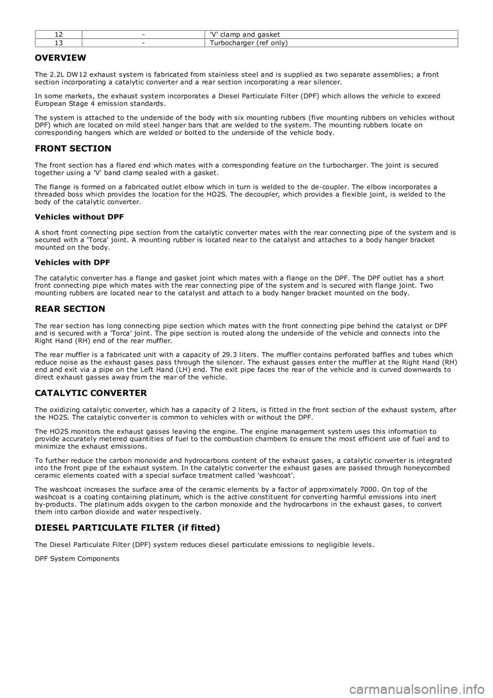
12-'V' cl amp and gas ket
13-Turbocharger (ref only)
OVERVIEW
The 2.2L DW 12 exhaus t s ys t em i s fabricated from s tainl ess st eel and i s s uppl ied as two s eparat e as sembl ies ; a fronts ect ion i ncorporati ng a catalyt ic converter and a rear sect ion i ncorporat ing a rear s il encer.
In s ome market s , the exhaus t s yst em incorporates a Dies el Parti cul ate Fi lt er (DPF) which all ows the vehicl e to exceedEuropean Stage 4 emis s ion s tandards .
The s ys t em i s att ached to t he unders ide of t he body wit h s ix mount ing rubbers (fi ve mount ing rubbers on vehicles wi thoutDPF) which are locat ed on mild st eel hanger bars t hat are wel ded to t he s yst em. The mounti ng rubbers locat e oncorres pondi ng hangers which are welded or bolt ed to the unders i de of the vehicle body.
FRONT SECTION
The front sect ion has a flared end which mat es wit h a corres ponding feature on t he turbocharger. The joint i s s ecuredt oget her us ing a 'V' band cl amp s ealed wi th a gasket .
The fl ange is formed on a fabricated out let elbow whi ch in turn is wel ded to the de-coupler. The elbow i ncorporat es at hreaded bos s whi ch provi des the locat ion for the HO2S. The decoupl er, which provi des a fl exi ble joint, i s welded t o t hebody of the catal yt ic convert er.
Vehicles without DPF
A s hort front connecti ng pipe s ecti on from t he catalyt ic converter mat es wit h t he rear connect ing pipe of t he s yst em and iss ecured wit h a 'Torca' joint. A mounti ng rubber is l ocat ed near t o t he cat alys t and att aches t o a body hanger bracketmounted on the body.
Vehicles with DPF
The cat alyt ic converter has a flange and gasket joi nt which mat es wit h a fl ange on the DPF. The DPF outl et has a s hortfront connect ing pi pe which mat es wi th t he rear connect ing pipe of t he s yst em and is s ecured wi th flange joint. Twomounti ng rubbers are l ocated near t o t he cat alys t and att ach to a body hanger bracket mount ed on the body.
REAR SECTION
The rear s ect ion has l ong connecti ng pipe s ect ion whi ch mat es wit h t he front connecting pi pe behi nd the cat alyst or DPFand is secured wi th a 'Torca' joi nt. The pipe secti on is routed al ong the unders i de of the vehicle and connect s int o t heRight Hand (RH) end of t he rear muffl er.
The rear muffl er i s a fabri cat ed uni t wit h a capacit y of 29.3 l it ers . The muffler cont ains perforat ed baffl es and t ubes whi chreduce nois e as t he exhaus t gases pas s t hrough the si lencer. The exhaus t gas s es enter t he muffler at t he Right Hand (RH)end and exit via a pipe on t he Left Hand (LH) end. The exit pi pe faces the rear of the vehicle and is curved downwards t odirect exhaus t gas ses away from t he rear of the vehicle.
CATALYTIC CONVERTER
The oxidizing cat al yti c convert er, which has a capacit y of 2 li ters, i s fit ted i n t he front secti on of the exhaust sys tem, aftert he HO2S. The cat al yti c convert er is common t o vehicles wi th or wit hout t he DPF.
The HO2S moni tors the exhaust gas s es leavi ng t he engi ne. The engine management s ys t em us es t hi s informat ion t oprovide accuratel y met ered quant it ies of fuel t o t he combus t ion chambers t o ens ure the mos t efficient us e of fuel and t omi ni mi ze the exhaus t emi s si ons .
To furt her reduce t he carbon monoxi de and hydrocarbons content of t he exhaus t gas es , a catalyt ic converter i s int egratedint o t he front pi pe of the exhaust sys tem. In t he catalyt ic converter t he exhaus t gases are pass ed t hrough honeycombedceramic el ements coated wit h a s peci al surface t reatment call ed 'was hcoat '.
The was hcoat increas es the surface area of t he cerami c elements by a fact or of approximat ely 7000. On t op of thewas hcoat is a coat ing contai ni ng plat inum, which i s t he act ive const it uent for convert ing harmful emi ss i ons i nto inertby-products . The plat inum adds oxygen to t he carbon monoxide and t he hydrocarbons in t he exhaus t gases , t o convertt hem int o carbon dioxide and wat er res pect ively.
DIESEL PARTICULATE FILTER (if fitted)
The Dies el Parti cul ate Fi lt er (DPF) s ys t em reduces dies el parti cul at e emi s si ons to negl igible levels .
DPF Syst em Components
Page 1533 of 3229
DPF Air Management Module
The DPF air management modul e control s t he fol lowing funct ions :
EGR controlTurbocharger boos t pres sure cont rolInt ake air t emperature and pres s ure control.
Duri ng act ive regenerat ion, t he EGR operat ion i s dis abl ed and t he cl osed-loop acti vat ion of t he t urbocharger boostcont rol ler is calculat ed. The ai r management module cont rols the ai r in t he int ake manifol d t o a predet ermi ned level ofpres s ure and t emperat ure. Thi s cont rol i s required t o achi eve the correct i n-cylinder condi ti ons for s table and robustcombus t ion of t he post i njected fuel.
The module controls t he i nt ake air t emperature by actuati ng t he EGR t hrott le and by adjus tment of t he turbocharger boos tpres s ure control.
DPF Co-ordinator Module
The DPF co-ordi nat or module react s t o a regenerat ion reques t from the s upervis or module by i nit iat ing and co-ordi nat ingt he foll owing DPF regenerat ion reques t s :
EGR cut-offTurbocharger boos t pres sure cont rolEngi ne load i ncreaseControl of air press ure and temperat ure in t he i nt ake manifoldFuel i njecti on cont rol.
W hen t he s upervis or modul e i ss ues a regenerat ion reques t , the co-ordinator module reques t s EGR cut-off and aregenerat ion s peci fi c turbocharger boos t pres s ure control. It then wai ts for a feedback s ignal from t he EGR s ys t emconfirming that the EGR val ve is cl osed.
W hen t he EGR valve i s clos ed, t he co-ordi nator module i nit iat es reques t s t o increas e engine l oad by cont roll ing t he i nt akeair t emperature and pres s ure.
Once confirmati on is recei ved that int ake condit ions are cont rol led or a cali brati on t ime has expired, the co-ordinatormodule t hen changes t o a s t ate awai ti ng an accelerator pedal release manoeuver from t he dri ver. If t his occurs or acal ibrat ion ti me has expired, t he co-ordi nat or modul e generates a request t o control fuel injecti ons to increas e exhaus tgas temperature.
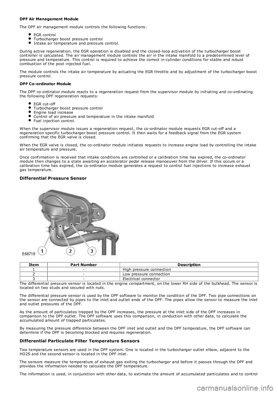
Differential Pressure Sensor
ItemPart NumberDescription
1-High press ure connect ion2-Low pres s ure connect ion
3-Electrical connect or
The different ial pres s ure s ensor i s located i n t he engi ne compart ment , on t he lower RH si de of the bul khead. The sens or islocated on two st uds and s ecured wit h nuts .
The different ial pres s ure s ensor i s us ed by the DPF software t o monit or the condit ion of t he DPF. Two pi pe connecti ons ont he sens or are connect ed by pipes t o t he inlet and out let ends of t he DPF. The pipes all ow t he s ens or to measure t he inletand outl et press ures of t he DPF.
As t he amount of parti culat es t rapped by the DPF increases , t he pres sure at t he inlet s i de of the DPF i ncreas es i ncomparis on t o t he DPF outl et . The DPF s oft ware us es t his compari son, in conduct ion wit h other data, t o calculate theaccumulat ed amount of trapped part iculat es.
By meas uri ng the press ure difference between t he DPF i nl et and out let and t he DPF t emperature, the DPF s oftware candetermine i f the DPF is becoming bl ocked and requires regenerat ion.
Differential Particulate Filter Temperature Sensors
Two t emperature s ensors are us ed i n t he DPF s ys t em. One is locat ed i n t he turbocharger out let el bow, adjacent to theHO2S and t he s econd s ensor i s located i n t he DPF inl et .
The s ens ors measure t he temperat ure of exhaust gas exit ing the t urbocharger and before i t pas s es t hrough the DPF andprovides t he informat ion needed to cal cul at e t he DPF t emperature.
The informat ion i s us ed, i n conjunct ion wi th other dat a, to est imat e t he amount of accumulat ed parti cul ates and t o control
Page 1547 of 3229
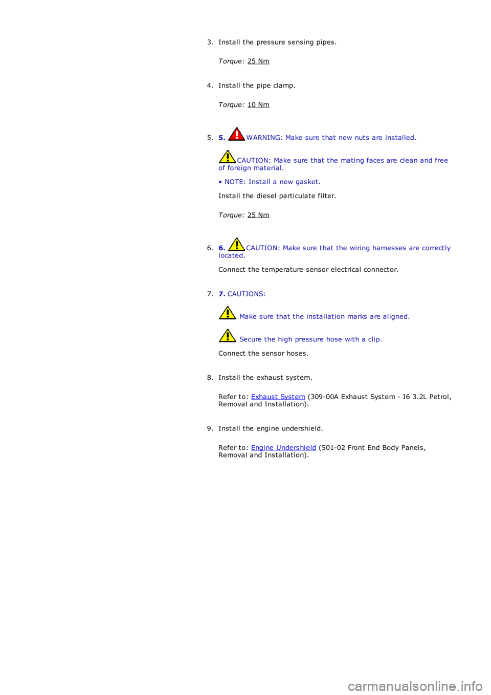
Inst all t he pres sure s ensi ng pipes .
T orque: 25 Nm 3.
Inst all t he pipe clamp.
T orque: 10 Nm 4.
5. W ARNING: Make sure t hat new nut s are ins tal led.
CAUTION: Make s ure that t he mati ng faces are cl ean and free
of foreign mat eri al .
• NOTE: Inst all a new gas ket.
Inst all t he dies el parti culat e fil ter.
T orque: 25 Nm 5.
6. CAUTION: Make s ure that the wiring harnes s es are correct ly
l ocated.
Connect t he temperature s ens or electrical connect or.
6.
7. CAUTIONS: Make s ure that t he ins tal lat ion marks are al igned.
Secure t he high press ure hose wit h a cli p.
Connect t he s ens or hoses .
7.
Inst all t he exhaus t sys t em.
Refer t o: Exhaus t Sys t em (309-00A Exhaus t Sys t em - I6 3.2L Pet rol ,
Removal and Ins tall ati on).
8.
Inst all t he engi ne undershi eld.
Refer t o: Engi ne Unders hi eld (501-02 Front End Body Panel s ,
Removal and Ins tall ati on).
9.