Page 1353 of 3229
19. W ARNING: Make sure t hat new nut s are
i ns t alled.
Connect t he ti e-rod end ball joi nts .
T orque: 80 Nm 19.
20. W ARNING: Make sure t hat new nut s are
i ns t alled. CAUTION: Make s ure that t he bal l joi nt bal l does
not rot ate.
Connect both front s t abi li zer bar li nks to the s t abi li zer
bar.
T orque: 55 Nm 20.
21.
NOTE: RH i llus t rati on s hown, LH is s imil ar.
Inst all t he LH fender s pl ash s hi eld ext ens ion panel.
21.
Inst all t he front wheel s and ti res .
Refer t o: W heel and Ti re (204-04 W heel s and Tires, Removal and
Inst all at ion).
22. Inst all t he towi ng eye cover.
T orque: Bumper cover securi ng bol ts 10 Nm 23.
Secure and connect the sel ect or lever cable.
24.
Page 1364 of 3229
Connect and s ecure t he cool ant hos es.
2.
Inst all t he transmis si on fluid cooler.
T orque: 10 Nm 3.
Connect t he batt ery ground cable and ins tall t he cover.
Refer t o: Specificati ons (414-00 Bat tery and Charging Sys tem -
General Informat ion, Specificati ons).
4.
Refi ll t he transmis s ion wi th flui d.
Refer t o: Transmis s ion Flui d Drai n and Refi ll - I6 3.2L Pet rol (307-01
Automat ic Transmis si on/Trans axl e, General Procedures ).
5.
Page 1367 of 3229
Connect and s ecure t he cool ant hos es.
2.
Inst all t he transmis si on fluid cooler.
T orque: 10 Nm 3.
Connect t he batt ery ground cable and ins tall t he cover.
Refer t o: Specificati ons (414-00 Bat tery and Charging Sys tem -
General Informat ion, Specificati ons).
4.
Refi ll t he transmis s ion wi th flui d.
Refer t o: Transmis s ion Flui d Drai n and Refi ll - TD4 2.2L Dies el (307-01 Automat ic Trans mi s si on/Trans axl e, General Procedures ).
5.
Page 1370 of 3229

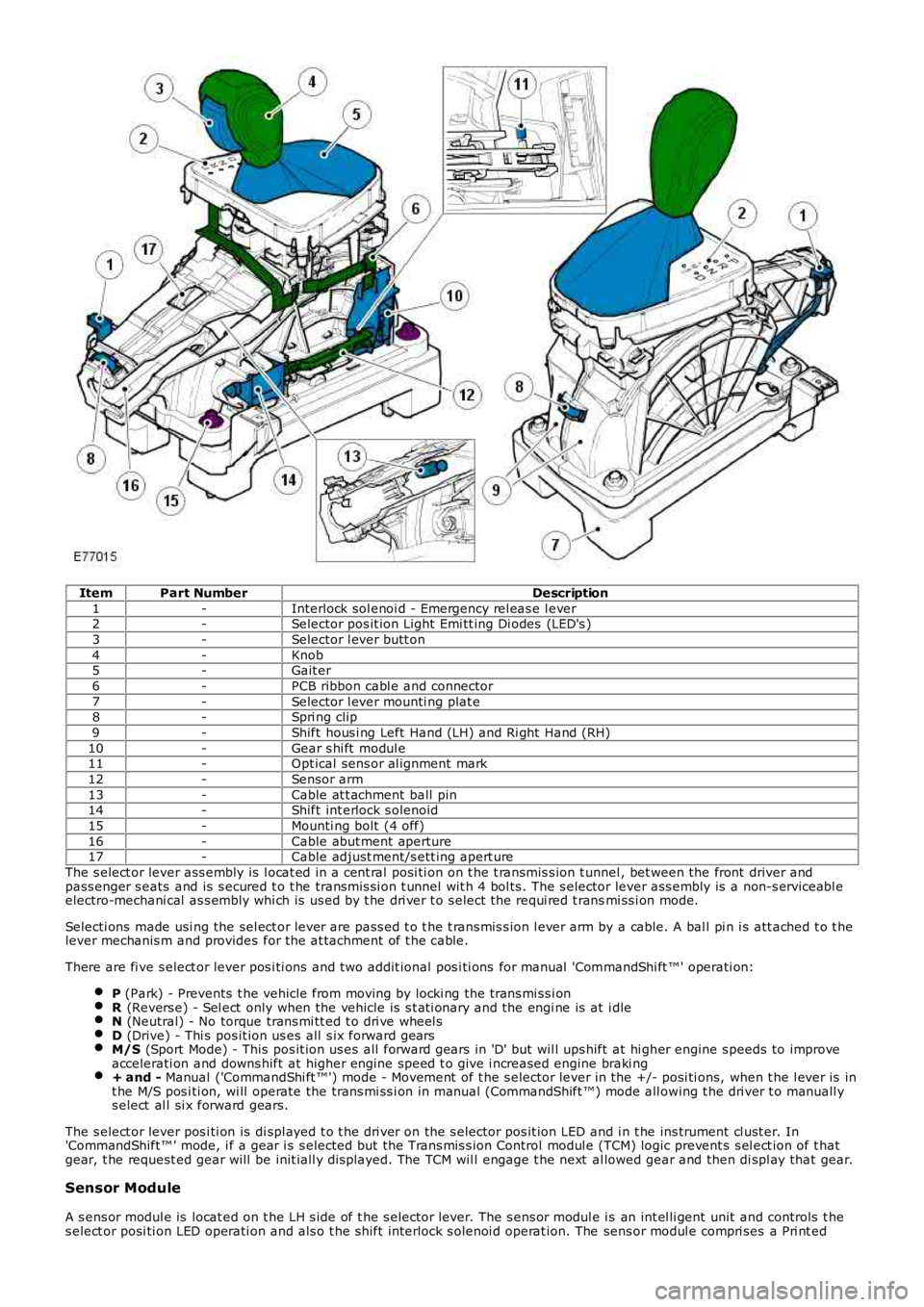
ItemPart NumberDescription
1-Interlock sol enoi d - Emergency rel eas e l ever2-Selector pos it ion Light Emi tt ing Di odes (LED's )
3-Selector l ever butt on
4-Knob5-Gait er
6-PCB ribbon cabl e and connector
7-Selector l ever mounti ng plat e8-Spri ng clip
9-Shift hous i ng Left Hand (LH) and Ri ght Hand (RH)
10-Gear s hi ft modul e11-Opt ical sens or al ignment mark
12-Sensor arm
13-Cable at t achment ball pin14-Shift int erlock s olenoid
15-Mounti ng bolt (4 off)
16-Cable abut ment aperture17-Cable adjust ment/s ett ing apert ure
The s elect or lever ass embly is l ocat ed in a cent ral posi ti on on t he t ransmis s ion t unnel , bet ween the front driver andpass enger s eats and is s ecured t o t he transmis si on t unnel wit h 4 bol ts . The s elector lever ass embly is a non-s erviceabl eelectro-mechani cal as s embly whi ch is us ed by t he dri ver t o s elect the requi red t ransmi ss i on mode.
Selecti ons made usi ng the sel ect or lever are pass ed t o t he t rans mis s ion l ever arm by a cable. A bal l pi n i s att ached t o t helever mechanis m and provides for the at tachment of t he cable.
There are fi ve s elect or lever pos i ti ons and t wo addit ional pos i ti ons for manual 'CommandShi ft ™' operati on:
P (Park) - Prevents t he vehicle from moving by locki ng the trans mi ss i onR (Revers e) - Sel ect only when the vehicle is s t ati onary and the engi ne is at i dleN (Neutral) - No torque trans mi tt ed t o dri ve wheel sD (Drive) - Thi s pos it ion us es all s ix forward gearsM/S (Sport Mode) - This pos it ion us es all forward gears in 'D' but wil l ups hift at hi gher engine s peeds to improveaccelerati on and downs hift at higher engine speed t o give i ncreased engine braki ng+ and - Manual ('CommandShi ft ™') mode - Movement of t he s elector lever in the +/- posi ti ons, when t he l ever is int he M/S pos i ti on, wi ll operate the trans mi ss i on in manual (CommandShift ™) mode all owing t he dri ver t o manuall ys elect al l si x forward gears.
The s elect or lever pos i ti on is di spl ayed t o t he dri ver on the s elector pos it ion LED and i n t he ins trument cl ust er. In'CommandShift™ ' mode, i f a gear i s s elected but t he Trans mis s ion Control modul e (TCM) logic prevent s s el ect ion of t hatgear, t he request ed gear will be init iall y dis played. The TCM wil l engage t he next al lowed gear and then di spl ay that gear.
Sensor Module
A s ens or modul e is locat ed on t he LH s ide of t he s elector lever. The s ens or modul e is an int el li gent unit and controls t hes elect or posi ti on LED operati on and als o t he s hift interlock s olenoi d operat ion. The sens or modul e compri ses a Pri nt ed
Page 1377 of 3229
Lock the s elector cable adjus t er.6.
Secure t he gear s elector cover.7.
Inst all t he gear s elector knob.
Refer t o: Sel ect or Lever Knob (307-05, Removal and Ins tall ati on).
8.
Page 1382 of 3229

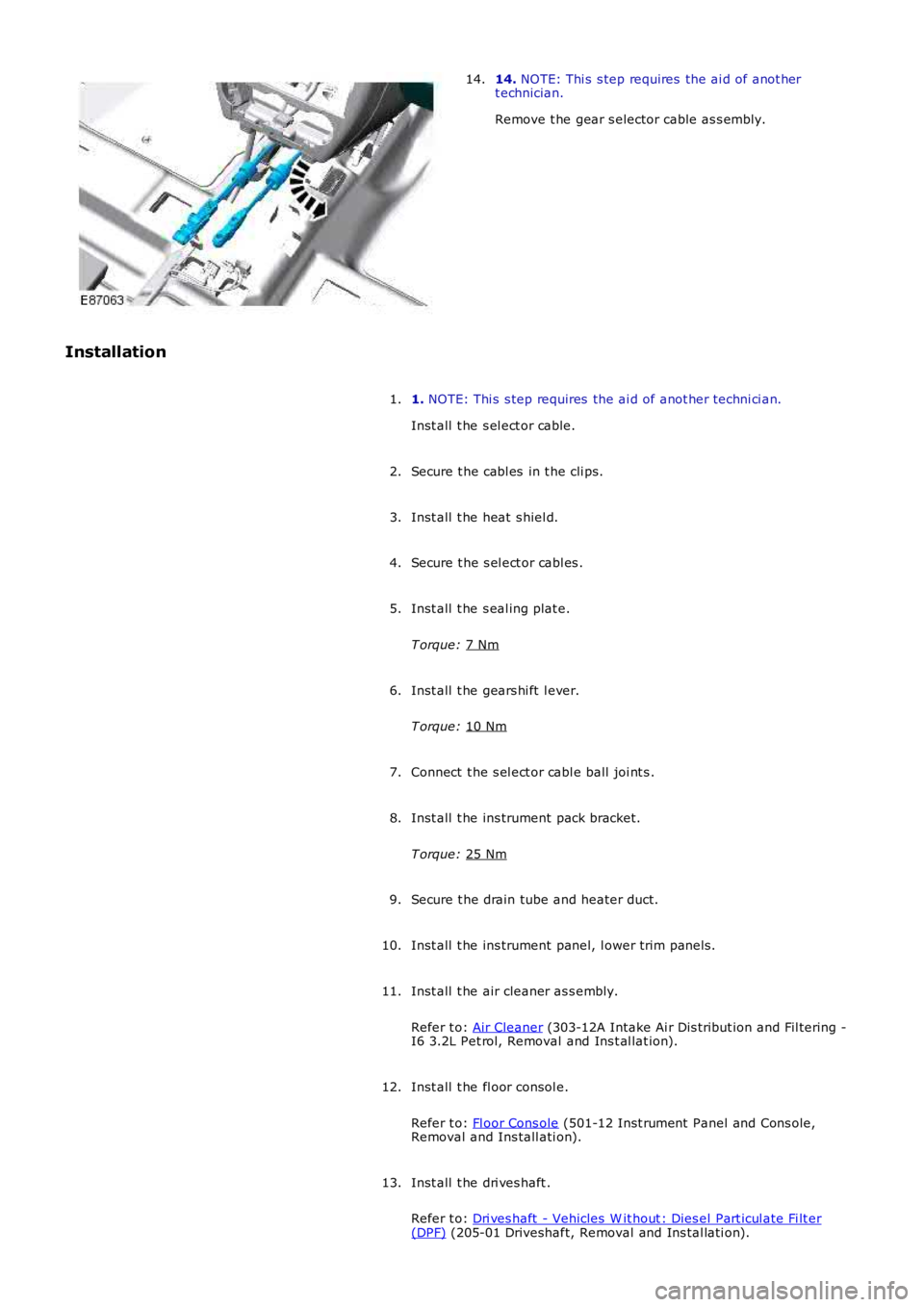
14.
NOTE: Thi s s tep requires the ai d of anot her
t echnician.
Remove t he gear s elector cable as s embly.
14.
Installation 1. NOTE: Thi s s tep requires the ai d of anot her techni ci an.
Inst all t he s el ect or cable.
1.
Secure t he cabl es in t he cli ps.
2.
Inst all t he heat s hiel d.
3.
Secure t he s el ect or cabl es .
4.
Inst all t he s eal ing plat e.
T orque: 7 Nm 5.
Inst all t he gears hi ft l ever.
T orque: 10 Nm 6.
Connect t he s el ect or cabl e ball joi nt s .
7.
Inst all t he ins trument pack bracket.
T orque: 25 Nm 8.
Secure t he drain tube and heater duct.
9.
Inst all t he ins trument panel, l ower trim panel s.
10.
Inst all t he air cleaner as s embly.
Refer t o: Air Cleaner (303-12A Intake Ai r Dis tribut ion and Fil tering -
I6 3.2L Pet rol, Removal and Ins t al lat ion).
11.
Inst all t he fl oor consol e.
Refer t o: Fl oor Cons ole (501-12 Inst rument Panel and Cons ole,
Removal and Ins tall ati on).
12.
Inst all t he dri ves haft .
Refer t o: Dri ves haft - Vehicles W it hout : Dies el Part icul ate Fi lt er (DPF) (205-01 Driveshaft, Removal and Ins tal lati on).
13.
Page 1389 of 3229
5. NOTE: Make s ure t he cut out on t he l ocking ringfaces t owards t he front of t he vehicle.
Inst all t he locki ng ring.
5.
Secure i nt o t he 3 cli ps.6.
Swit ch t he ignit ion on.7.
Pos it ion t he transmis s ion s elector lever int o PARK.8.
Page 1402 of 3229

The dri ven pl ate is t he cent ral connecti on element i n the cl utch. In combi nat ion wi th the cl ut ch cover as sembl y, its eparates and l inks engi ne and powert rain by connect ing the engine cranks haft t o t he trans mi s si on input s haft.
The dri ven pl ate is a ri gi d t ype fricti on plat e. The flywheel is of t he dual mas s t ype and abs orbs torque fluct uat ionsgenerated by t he combust ion proces s es to reduce noi s e and wear in t he t rans mis s ion.
Dual Mass Flywheel
The dual mas s flywheel compris es t wo main components ; t he pri mary s i de which i s att ached t o t he engi ne crankshaft andt he secondary s ide t o whi ch the clut ch cover as sembl y is at t ached.
The pri mary si de has the st art er ri ng gear at tached to it s outer circumference. The ring gear is us ed by t he s tarter mot or torot ate the engine during engine crank at s t art up. The primary s ide is s ecured t o t he cranks haft wi th eight bol ts . A dowelin the cranks haft flange ens ures that t he fl ywheel is correctl y located.
The s econdary s ide has the s moot h frict ion s urface on which t he dri ven pl ate fri cti on material engages . Dowel s and fixingholes all ow for the correct al ignment and att achment of the cl utch cover as s embl y.
The pri mary and secondary s ides are connect ed wi th l ong coi l springs . The two si des can rotat e agains t each ot her, li mi tedby t he coi l springs , whi ch absorb t orque loading on cl ut ch engagement and t ors ional vi brati ons from t he engine.