2006 LAND ROVER FRELANDER 2 ECU
[x] Cancel search: ECUPage 1131 of 3229
Publi s hed: 11-May-2011
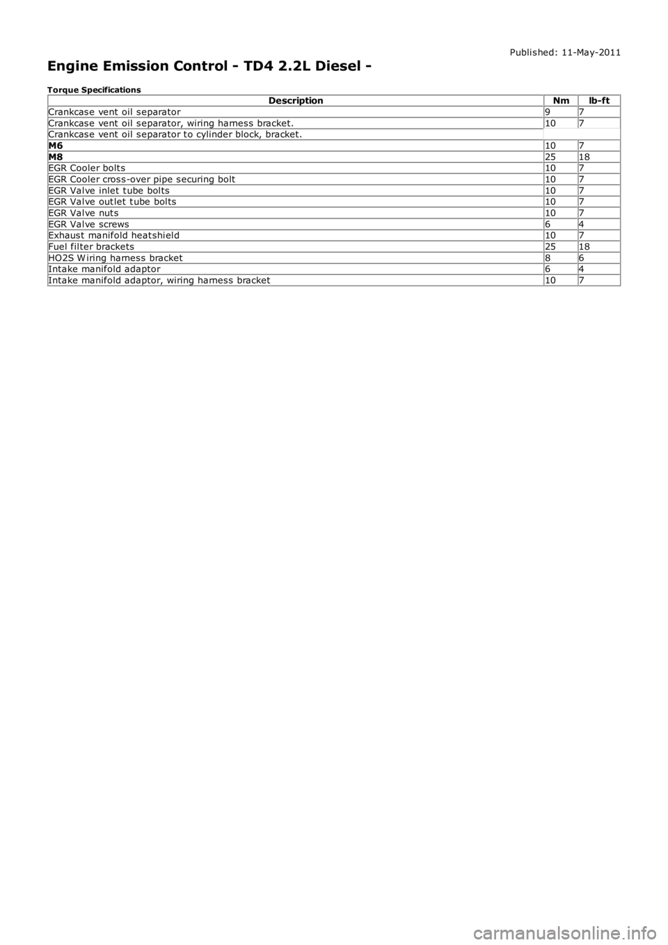
Engine Emission Control - TD4 2.2L Diesel -
Torque SpecificationsDescriptionNmlb-ft
Crankcas e vent oil s eparator97
Crankcas e vent oil s eparator, wiring harnes s bracket.107Crankcas e vent oil s eparator t o cylinder block, bracket.
M6107
M82518EGR Cooler bolt s107
EGR Cooler cros s -over pipe s ecuring bolt107
EGR Val ve inlet t ube bol ts107EGR Val ve out let t ube bol ts107
EGR Val ve nut s107
EGR Val ve screws64Exhaus t manifold heat shi el d107
Fuel fil ter brackets2518
HO2S W iring harnes s bracket86Intake manifold adaptor64
Intake manifold adaptor, wiring harnes s bracket107
Page 1134 of 3229
module), regulates t he amount of exhaus t gas es reci rculated into the ai r int ake s ys tem. The ECM uses s i gnals fromvarious engine s ens ors and calculates a res pons e bas ed on t he embedded software algori thm t o cont rol exhaus t gasrecircul ati on. The ECM trans mi ts this cont rol s ignal t o t he valve's actuat or, which i s clos ed-loop controlled wit h t he mas sair flow (MAF) s ens or providi ng the feedback t o t he ECM.
COMPONENT DESCRIPTION
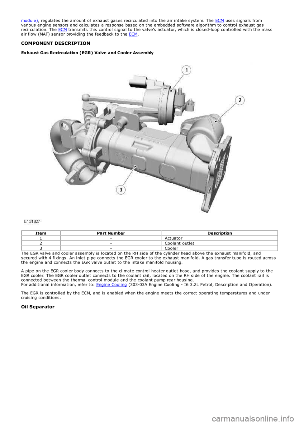
Exhaust Gas R ecirculation (EGR) Valve and Cooler Assembly
ItemPart NumberDescription1-Actuator
2-Coolant out let
3-CoolerThe EGR valve and cooler ass embl y is l ocat ed on t he RH s ide of t he cylinder head above t he exhaus t manifold, ands ecured wit h 4 fixi ngs . An i nl et pipe connects the EGR cooler t o t he exhaus t manifold. A gas t rans fer t ube is rout ed acros st he engi ne and connect s t he EGR valve out let t o the intake mani fold hous ing.
A pi pe on t he EGR cool er body connect s to the cl imat e cont rol heater outl et hos e, and provides t he cool ant s upply t o t heEGR cooler. The EGR cooler outl et connect s t o t he cool ant rail , locat ed on t he RH s ide of the engine. The cool ant rail isconnected bet ween the t hermal control modul e and the coolant pump rear hous ing.For addit ional informat ion, refer t o: Engi ne Cooling (303-03A Engine Cooli ng - I6 3.2L Pet rol, Des cri pt ion and Operati on).
The EGR i s cont rol led by t he ECM, and is enabled when t he engine meet s t he correct operati ng temperatures and undercruis i ng condit ions .
Oil Separator
Page 1143 of 3229
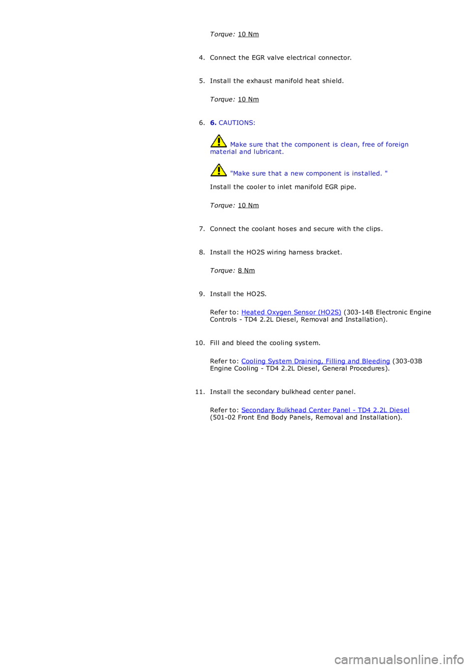
T orque:
10 Nm Connect t he EGR valve elect rical connector.
4.
Inst all t he exhaus t manifol d heat shi eld.
T orque: 10 Nm 5.
6. CAUTIONS: Make s ure that t he component is cl ean, free of foreign
mat eri al and l ubricant. "Make s ure t hat a new component i s ins t al led. "
Inst all t he cool er t o i nlet manifold EGR pi pe.
T orque: 10 Nm 6.
Connect t he cool ant hos es and s ecure wit h t he clips .
7.
Inst all t he HO2S wi ring harnes s bracket.
T orque: 8 Nm 8.
Inst all t he HO2S.
Refer t o: Heat ed Oxygen Sens or (HO2S) (303-14B Electroni c Engine
Controls - TD4 2.2L Dies el, Removal and Ins tal lati on).
9.
Fil l and bl eed the cooli ng s ys t em.
Refer t o: Cool ing Sys tem Drai ni ng, Fi lli ng and Bleeding (303-03B
Engine Cooli ng - TD4 2.2L Di esel , General Procedures ).
10.
Inst all t he s econdary bulkhead cent er panel.
Refer t o: Secondary Bulkhead Cent er Panel - TD4 2.2L Dies el (501-02 Front End Body Panel s, Removal and Ins tal lati on).
11.
Page 1160 of 3229
Publi s hed: 11-May-2011
Intake Air Distribution and Filtering - I6 3.2L Petrol - Intake Air
Distribution and Filtering
Diagnosi s and Tes ti ng
Principles of Operation
For a detail ed descripti on of the intake ai r di s tributi on and fi lt eri ng sys t em, refe r t o t he rel evant Des cript ion and Operat ion
s ect ion i n t he works hop manual .
REFER to: Intake Air Di s tributi on and Fil teri ng (303-12A Int ake Air Dis t ri but ion and Fi lt ering - I6 3.2L Petrol, Des cript ion
and Operat ion).
Inspection and Verification CAUTION: Di agnos is by s ubs ti tut ion from a donor vehicle is
NO T acceptabl e. Subs ti tut ion of cont rol modules does
not guarant ee confirmat ion of a faul t, and may als o caus e addit ional fault s i n t he v ehi cl e being t est ed and/or t he donor
vehi cl e.
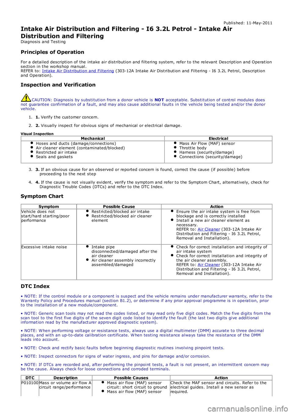
1. Verify t he cus t omer concern.
1.
2. Vis ually ins pect for obvious s igns of mechani cal or electrical damage.
2.
Visual Inspection Mechanical Electrical
Hos es and duct s (damage/connect ions ) Air cl eaner element (contaminated/bl ocked)
Res tricted ai r int ake
Seals and gas ket s Mass Air Flow (MAF) s ens or
Thrott le body
Harness (s ecurit y/damage)
Connecti ons (s ecurit y/damage)
3.
If an obvious cause for an obs erved or report ed concern is found, correct t he caus e (if pos s ible) before
proceeding t o t he next s t ep
3.
4. If t he caus e is not vis ually evi dent , verify t he sympt om and refer t o t he Sympt om Ch art, al ternat ively, check for
Di agnos ti c Trouble Codes (DTCs) and refer t o t he DTC Index.
4.
Symptom Chart Symptom Possible Cause Action
Vehicle does not
s tart/hard s t art ing/poor
performance Res t ri ct ed/blocked air int ake Res t ri ct ed/blocked air cleaner
el ement Ensure t he air int ake s ys t em i s free from
blockage and i s correct ly i nst all ed Ins t all a new ai r cl eaner element as
neces s ary.
REFER to: Ai r Cl eaner (303-12A Int ake Air
Dis t ri but ion and Fi lt ering - I6 3.2L Petrol,
Removal and Inst all ati on). Exces s ive i nt ake nois e
Int ake pi pe
di s connect ed/damaged aft er the
ai r cl eaner Ai r cleaner as s embly i ncorrect ly
as s embled/damaged Check for correct ins tal lat ion and i nt egri ty of
air i nt ake s ys t em Check for correct ins tal lat ion and i nt egri ty of
t he air cleaner as s embly.
REFER to: Ai r Cl eaner (303-12A Int ake Air
Dis t ri but ion and Fi lt ering - I6 3.2L Petrol,
Removal and Inst all ati on). DTC Index
• NOTE: If the control modul e or a component i s s us pect and the vehicle remains unde r manufacturer warrant y, refer t o the
W arranty Pol icy and Procedures manual (s ect ion B1.2), or determine i f any pri or appr oval programme is in operat ion, pri or
t o the ins tall ati on of a new module/component.
• NOTE: Generic scan t ool s may not read the codes li st ed, or may read only fi ve digi t codes . Mat ch the five di git s from t he
s can tool to the firs t fi ve di git s of the seven digi t code l is ted to ident ify t he fa ul t (t he las t t wo digi ts gi ve addi ti onal
informat ion read by the manufact urer approved diagnos t ic s ys tem).
• NOTE: W hen performing volt age or res is t ance t est s , always use a digi tal mult imeter (DMM) accurat e t o t hree deci mal
places, and wi th an up-t o-date cal ibrat ion cert ificate. W hen tes ti ng res is t ance al wa ys take t he res is t ance of t he DMM
leads i nt o account .
• NOTE: Check and recti fy bas ic faul ts before beginni ng diagnos t ic rout ines i nvol vi n g pinpoint t es t s.
• NOTE: Ins pect connect ors for s igns of water ingres s , and pins for damage and/or co rros ion.
• NOTE: If DTCs are recorded and, aft er performi ng the pi npoi nt tes ts , a fault is no t present , an int ermi tt ent concern may
be t he caus e. Always check for loose connect ions and corroded terminals .
DT C Description Possible Causes Action
P010100 Mas s or volume ai r fl ow A
circui t range/performance Mas s ai r fl ow (MAF) s ens or
ci rcuit : short ci rcuit t o ground Mas s ai r fl ow (MAF) s ens or Check t he MAF s ensor and circui ts . Refer t o t he
electrical gui des . Ins t all a new s ens or as
required.
Page 1169 of 3229
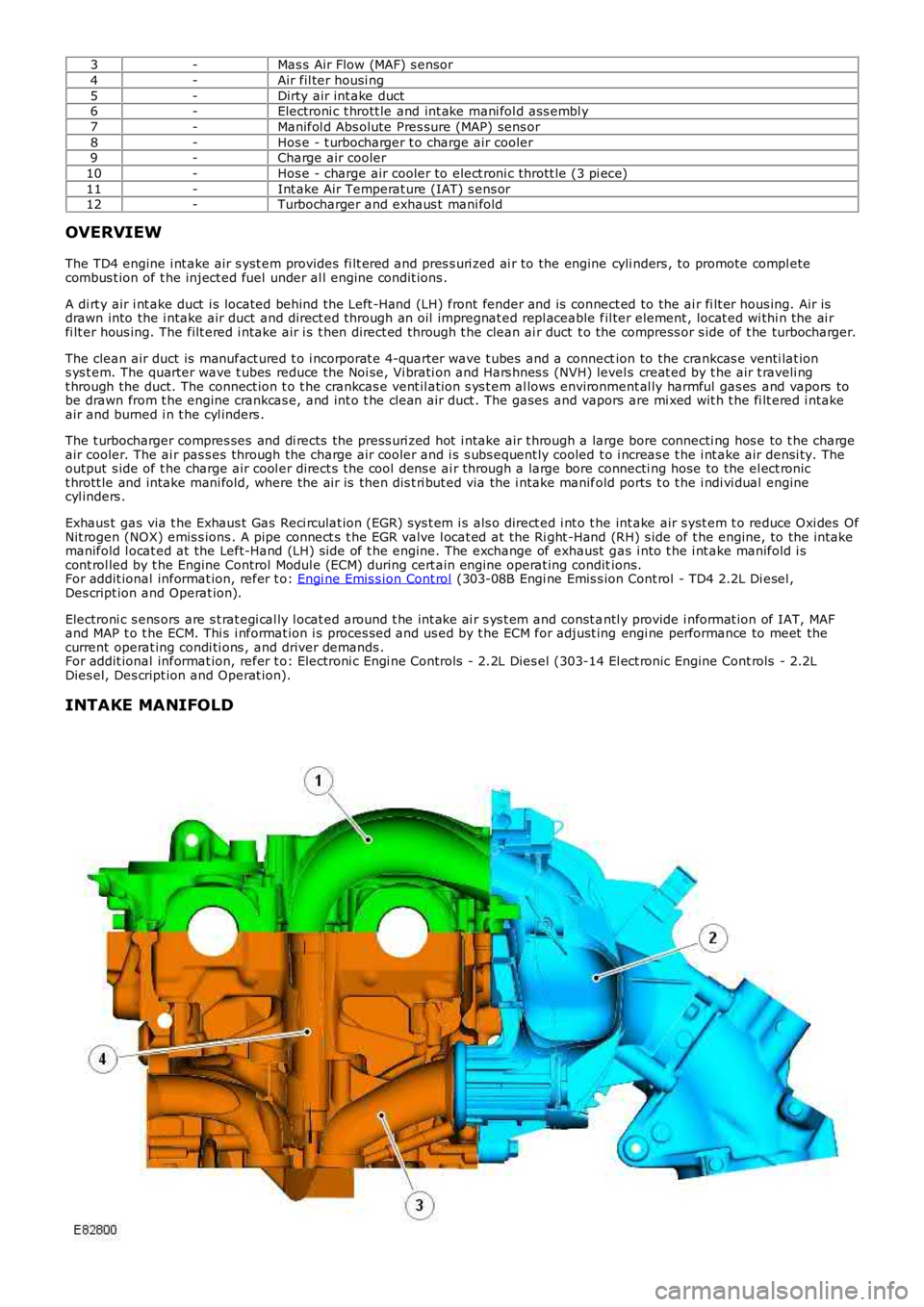
3-Mas s Air Flow (MAF) s ensor
4-Air fil ter housi ng
5-Dirty air int ake duct6-Electroni c t hrott le and int ake mani fol d ass embl y
7-Manifol d Abs olute Pres sure (MAP) sens or
8-Hos e - t urbocharger t o charge air cooler9-Charge air cooler
10-Hos e - charge air cooler to elect roni c thrott le (3 pi ece)
11-Int ake Air Temperat ure (IAT) s ens or12-Turbocharger and exhaus t mani fold
OVERVIEW
The TD4 engine i nt ake air s yst em provides fi lt ered and pres s uri zed ai r to the engine cyli nders , to promote compl etecombus t ion of t he inject ed fuel under al l engine condit ions .
A di rt y air i nt ake duct i s located behind the Left -Hand (LH) front fender and is connect ed to the ai r fi lt er hous ing. Air isdrawn into the i ntake air duct and direct ed through an oil impregnat ed repl aceable fil ter element , locat ed wi thi n the ai rfi lt er hous ing. The filt ered i ntake air i s t hen direct ed through t he clean ai r duct t o the compress or s ide of t he turbocharger.
The clean air duct is manufact ured t o i ncorporat e 4-quarter wave t ubes and a connection to the crankcas e venti lat ions ys t em. The quarter wave t ubes reduce the Noi se, Vi brati on and Hars hnes s (NVH) levels creat ed by t he air t raveli ngt hrough the duct. The connect ion t o t he crankcas e vent il ati on s ys t em al lows environment al ly harmful gas es and vapors tobe drawn from t he engine crankcas e, and int o t he cl ean air duct . The gases and vapors are mi xed wit h t he fi lt ered i ntakeair and burned i n t he cyl inders .
The t urbocharger compres ses and di rects the press uri zed hot i ntake air t hrough a large bore connecti ng hos e to t he chargeair cooler. The ai r pas s es through the charge ai r cooler and i s s ubs equent ly cooled t o i ncreas e t he i nt ake air densi ty. Theoutput s ide of t he charge air cool er direct s the cool dens e ai r through a large bore connecti ng hose to the el ect ronict hrott le and intake mani fold, where the ai r is then dis t ri but ed via the i ntake manifold ports t o t he i ndi vi dual enginecyl inders .
Exhaus t gas via t he Exhaus t Gas Reci rculat ion (EGR) sys t em i s als o direct ed i nt o t he int ake air s yst em t o reduce Oxi des OfNit rogen (NOX) emis s ions . A pipe connect s t he EGR valve l ocat ed at the Ri ght -Hand (RH) s ide of t he engine, to the i ntakemanifold l ocat ed at the Left-Hand (LH) s ide of t he engine. The exchange of exhaust gas i nto t he i nt ake manifold i scont rol led by t he Engine Control Modul e (ECM) during cert ain engine operat ing conditions.For addit ional informat ion, refer t o: Engi ne Emis s ion Cont rol (303-08B Engi ne Emis s ion Cont rol - TD4 2.2L Di esel ,Des cript ion and Operat ion).
Electroni c s ens ors are s t rat egi cal ly l ocat ed around t he int ake ai r s ys t em and const antl y provide i nformat ion of IAT, MAFand MAP t o t he ECM. Thi s i nformat ion i s proces sed and us ed by t he ECM for adjust ing engi ne performance to meet thecurrent operat ing condi ti ons , and driver demands .For addit ional informat ion, refer t o: Electroni c Engi ne Controls - 2.2L Dies el (303-14 El ect ronic Engine Cont rols - 2.2LDies el, Des cript ion and Operat ion).
INTAKE MANIFOLD
Page 1172 of 3229
Publi s hed: 11-May-2011
Intake Air Distribution and Filtering - TD4 2.2L Diesel - Intake Air
Distribution and Filtering
Diagnosi s and Tes ti ng
Principles of Operation
For a detail ed descripti on of the intake ai r di s tributi on and fi lt eri ng sys t em, refer t o t he rel evant Des cript ion and Operat ions ect ion i n t he works hop manual .REFER to: Intake Air Di s tributi on and Fil teri ng (303-12B Int ake Air Dis t ri but ion and Fi lt ering - TD4 2.2L Di esel , Des cri pti onand Operat ion).
Inspection and Verification
CAUTION: Di agnos is by s ubs ti tut ion from a donor vehicle is NO T acceptabl e. Subs ti tut ion of cont rol modules doesnot guarant ee confirmat ion of a faul t, and may als o caus e addit ional fault s i n t he vehi cl e being t est ed and/or t he donorvehi cl e.
1. Verify t he cus t omer concern.1.
2. Vis ually ins pect for obvious s igns of mechani cal or electrical damage.2.
Visual InspectionMechanicalElectrical
Hos es and duct s (damage/connect ions )Air cl eaner element(cont aminated/bl ocked)Res tricted ai r int akeSeals and gas ket s
Mas s Ai r Fl ow (MAF) sens orSecondary Air Injecti on (AIR) Manifol d Abs ol ute Pres sure (MAP)s ens orThrot t le bodyHarnes s (s ecurit y/damage)Connect ions (s ecuri ty/damage)
3. If an obvious cause for an obs erved or report ed concern is found, correct t he caus e (if pos s ible) beforeproceeding t o t he next s t ep3.
4. If t he caus e is not vis ually evi dent , verify t he sympt om and refer t o t he Sympt om Chart, al ternat ively, check forDi agnos ti c Trouble Codes (DTCs) and refer t o t he DTC Index.4.
Symptom Chart
SymptomPossible CauseAction
Vehicle does not s tart/hards tarti ng/poor performanceRes t rict ed/blocked ai r int akeRes t rict ed/blocked ai r cleanerel ement
Ens ure the ai r int ake sys tem is freefrom bl ockage and is correctl y ins tal ledIns t al l a new ai r cl eaner element asneces sary.REFER to: Air Cl eaner Element (303-12,Removal and Inst all at ion).
Exces s ive i nt ake nois eIntake pi pe dis connect ed/damagedafter t he air cleanerAi r cl eaner as s embl y i ncorrect lyas s embled/damaged
Check for correct ins tal lati on andint egrit y of air i nt ake s ys t emCheck for correct ins tal lati on andint egrit y of the ai r cleaner as s embly.REFER to: Air Cl eaner Element (303-12,Removal and Inst all at ion).
DTC Index
• NOTE: If the control modul e or a component i s s us pect and the vehicle remains under manufacturer warrant y, refer t o theW arranty Pol icy and Procedures manual (s ect ion B1.2), or determine i f any pri or approval programme is in operat ion, pri ort o the ins tall ati on of a new module/component.
• NOTE: Generic scan t ool s may not read the codes li st ed, or may read only fi ve digit codes . Mat ch the five di git s from t hes can tool to the firs t fi ve di git s of the seven digi t code l is ted to ident ify t he faul t (t he las t t wo digi ts gi ve addi ti onalinformat ion read by the manufact urer approved diagnos t ic s ys tem).
• NOTE: W hen performing volt age or res is t ance t est s , always use a digi tal mult imeter (DMM) accurat e t o t hree deci malplaces, and wi th an up-t o-date cal ibrat ion cert ificate. W hen tes ti ng res is t ance al ways take t he res is t ance of t he DMMleads i nt o account .
• NOTE: Check and recti fy bas ic faul ts before beginni ng diagnos t ic rout ines i nvol vi ng pinpoint t es t s.
• NOTE: Ins pect connect ors for s igns of water ingres s , and pins for damage and/or corros ion.
• NOTE: If DTCs are recorded and, aft er performi ng the pi npoi nt tes ts , a fault is not present , an int ermi tt ent concern maybe t he caus e. Always check for loose connect ions and corroded terminals .
DT CDescriptionPossible CausesAction
P006900MAP - Barometric Press ureCorrelat ionBoos t pres s ure s ensor circui t - s hort toground, power, open circui tBarometric pres s ure sens or fail ure
Carry out t he pinpoint t est sass ociated wit h t hi s DTC us ing t hemanufact urer approved diagnost ic
Page 1202 of 3229
12-Res trai nts Cont rol Module (RCM)
13-Knock sens ors (2 off)
14-Fuel rail t emperature/pres s ure s ens or15-Clockspring
16-Terrain respons e cont rol module
17-Trans mis s ion Cont rol Module (TCM)18-ABS module
19-Diagnos ti c socket
20-CJB
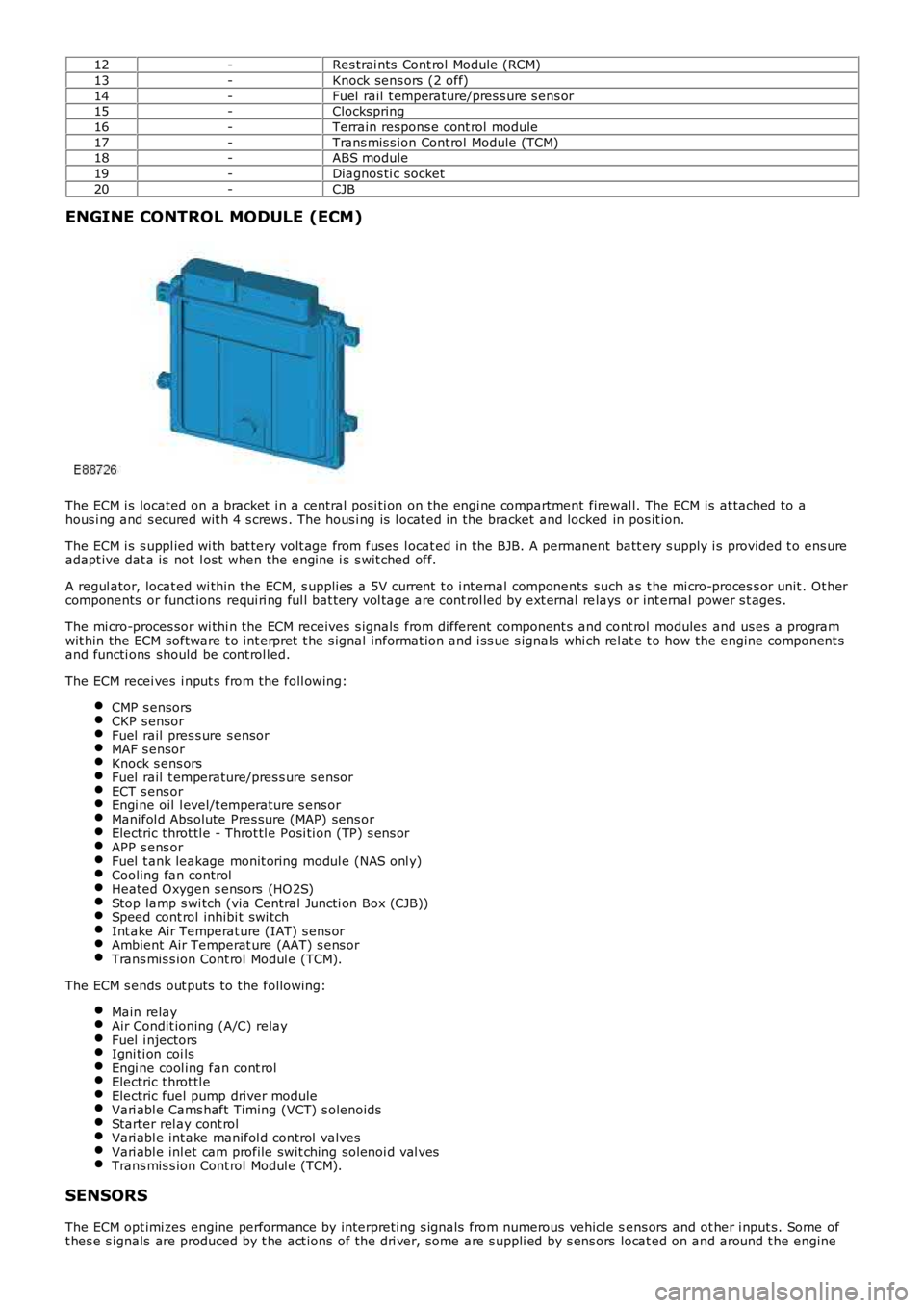
ENGINE CONTROL MODULE (ECM)
The ECM i s located on a bracket i n a central pos i ti on on the engi ne compartment firewal l. The ECM is at tached to ahous i ng and s ecured wit h 4 s crews . The hous i ng is l ocat ed in the bracket and locked in pos it ion.
The ECM i s s uppl ied wi th bat tery volt age from fuses l ocat ed in the BJB. A permanent batt ery s upply i s provided t o ens ureadapt ive dat a is not l ost when the engine i s s wit ched off.
A regul ator, locat ed wi thin the ECM, s upplies a 5V current t o i nt ernal components such as t he mi cro-proces s or unit . Ot hercomponents or funct ions requi ri ng ful l bat tery vol tage are cont rol led by ext ernal relays or int ernal power s t ages .
The mi cro-proces sor wi thi n the ECM receives s ignals from different component s and cont rol modules and us es a programwit hin the ECM software t o int erpret t he s ignal informat ion and i ss ue s ignals whi ch rel at e t o how the engine component sand functi ons should be cont rol led.
The ECM recei ves i nput s from the foll owing:
CMP s ensorsCKP s ensorFuel rail pres s ure s ensorMAF s ensorKnock s ens orsFuel rail t emperature/pres s ure s ensorECT s ens orEngi ne oil l evel/t emperature s ens orManifol d Abs olute Pres sure (MAP) sens orElectric t hrot tl e - Throt tl e Posi ti on (TP) s ens orAPP s ens orFuel t ank leakage monit oring modul e (NAS onl y)Cooling fan controlHeated Oxygen s ens ors (HO2S)Stop lamp s wi tch (via Central Juncti on Box (CJB))Speed cont rol inhibi t swi tchInt ake Air Temperat ure (IAT) s ens orAmbient Air Temperat ure (AAT) s ens orTrans mis s ion Cont rol Modul e (TCM).
The ECM s ends out puts to t he followi ng:
Main relayAir Condit ioning (A/C) relayFuel i njectorsIgni ti on coi lsEngi ne cool ing fan cont rolElectric t hrot tl eElectric fuel pump driver moduleVari abl e Cams haft Timing (VCT) s olenoidsStarter rel ay cont rolVari abl e int ake manifol d control valvesVari abl e inl et cam profile swit ching sol enoi d val vesTrans mis s ion Cont rol Modul e (TCM).
SENSORS
The ECM opt imi zes engine performance by interpreti ng s ignals from numerous vehicle sens ors and ot her i nput s. Some oft hes e s ignals are produced by t he act ions of t he dri ver, some are s uppli ed by s ens ors locat ed on and around t he engine
Page 1203 of 3229
and s ome are s uppli ed by ot her vehicle s ys tems .
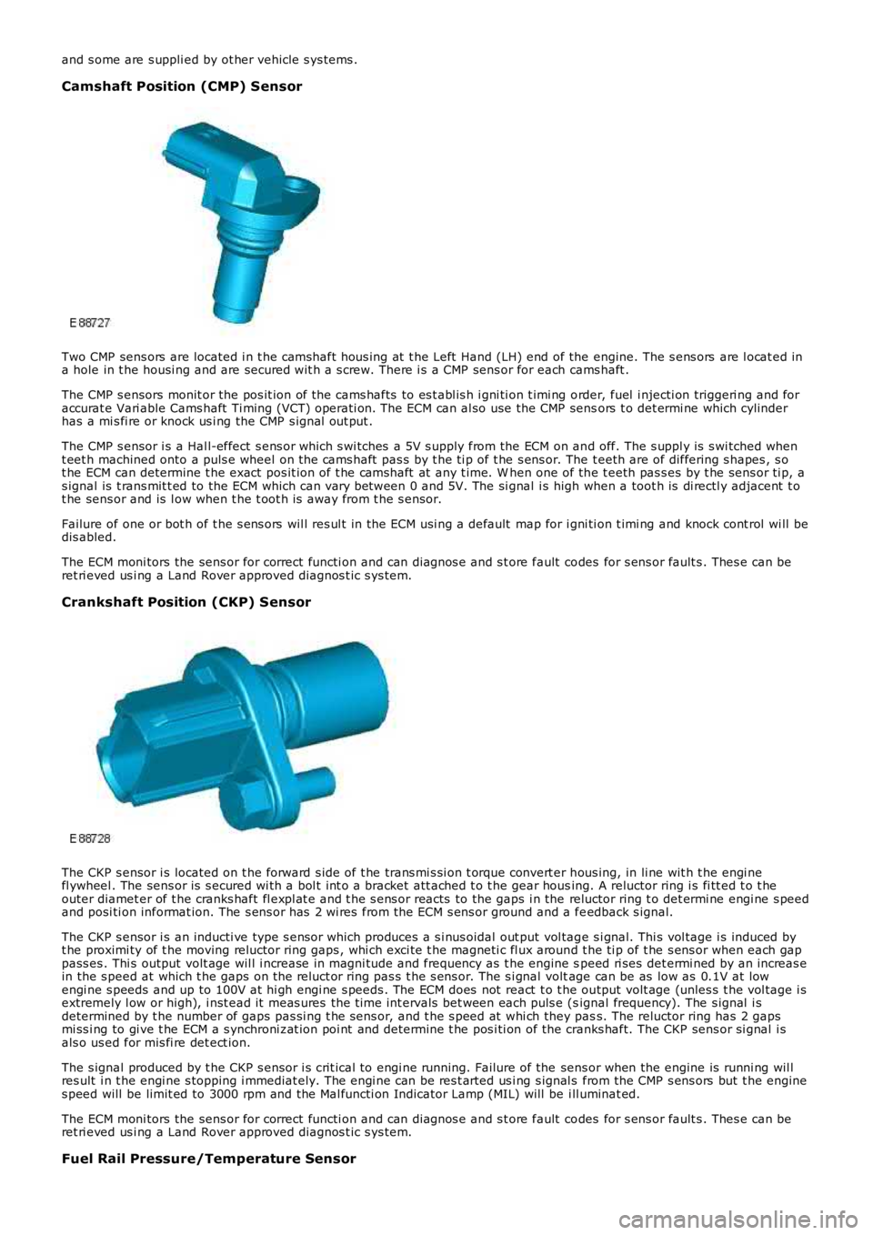
Camshaft Position (CMP) Sensor
Two CMP sens ors are located i n t he camshaft hous ing at t he Left Hand (LH) end of the engine. The s ens ors are l ocat ed ina hole in t he housi ng and are secured wit h a s crew. There i s a CMP sens or for each cams haft .
The CMP s ensors monit or the pos it ion of t he cams hafts to es t abl is h i gni ti on t imi ng order, fuel i njecti on triggeri ng and foraccurat e Vari able Cams haft Ti ming (VCT) operati on. The ECM can al so use the CMP sensors t o det ermi ne which cylinderhas a mi s fi re or knock us i ng the CMP s ignal out put .
The CMP s ensor i s a Hal l-effect s ens or which s wi tches a 5V s upply from the ECM on and off. The s uppl y is s wi tched whent eet h machined onto a puls e wheel on the cams haft pas s by t he ti p of t he s ens or. The t eeth are of differing s hapes , s ot he ECM can determine t he exact pos it ion of t he camshaft at any t ime. W hen one of the t eeth pas s es by t he sens or ti p, as ignal is t rans mit t ed to the ECM which can vary between 0 and 5V. The si gnal i s high when a toot h is di rectl y adjacent t ot he sens or and is l ow when t he t oot h i s away from t he s ensor.
Failure of one or bot h of t he s ens ors wil l res ul t in the ECM usi ng a default map for i gni ti on t imi ng and knock cont rol wi ll bedis abled.
The ECM moni tors the sens or for correct functi on and can diagnos e and s t ore fault codes for s ens or fault s . Thes e can beret ri eved us i ng a Land Rover approved diagnos t ic s ys tem.
Crankshaft Position (CKP) Sensor
The CKP s ensor i s located on t he forward s ide of t he trans mi s si on t orque convert er hous ing, in li ne wit h t he engi nefl ywheel . The sens or is s ecured wi th a bol t int o a bracket att ached t o t he gear housing. A reluctor ring i s fi tt ed t o t heouter diamet er of t he cranks haft fl expl at e and t he s ens or reacts to the gaps i n the reluctor ring t o det ermi ne engi ne s peedand posi ti on informat ion. The s ens or has 2 wi res from the ECM s ens or ground and a feedback s ignal.
The CKP s ensor i s an inducti ve type s ensor which produces a s i nus oidal out put vol tage s i gnal. Thi s vol tage i s induced byt he proximi ty of t he moving reluctor ring gaps , whi ch exci te t he magneti c fl ux around t he ti p of t he s ens or when each gappass es . Thi s output volt age wil l i ncrease in magni tude and frequency as t he engine speed ri ses det ermi ned by an increas ein the s peed at which t he gaps on t he reluct or ring pas s t he s ens or. The s i gnal voltage can be as low as 0.1V at lowengi ne s peeds and up to 100V at hi gh engi ne s peeds . The ECM does not react t o t he output volt age (unles s t he vol tage i sextremely l ow or high), i nst ead it meas ures the t ime int ervals bet ween each puls e (signal frequency). The s ignal i sdetermined by t he number of gaps pas si ng t he sens or, and t he s peed at whi ch they pass. The reluctor ring has 2 gapsmi ss i ng to gi ve t he ECM a s ynchroni zat ion poi nt and det ermi ne t he pos i ti on of the cranks haft. The CKP sens or si gnal i sals o us ed for mis fi re det ect ion.
The s ignal produced by t he CKP s ensor i s crit ical to engi ne running. Failure of the sens or when the engine is runni ng wil lres ult i n t he engi ne s topping i mmediat ely. The engi ne can be res t arted us i ng s ignal s from the CMP s ens ors but t he engines peed will be limit ed to 3000 rpm and the Mal functi on Indicator Lamp (MIL) will be ill uminat ed.
The ECM moni tors the sens or for correct functi on and can diagnos e and s t ore fault codes for s ens or fault s . Thes e can beret ri eved us i ng a Land Rover approved diagnos t ic s ys tem.
Fuel Rail Pressure/Temperature Sensor