2006 LAND ROVER FRELANDER 2 ECU
[x] Cancel search: ECUPage 1010 of 3229
Stage 1:
Stage 2:
Stage 1:
Stage 2: Make s ure that t he component is cl ean, free of foreign
mat eri al and l ubricant. Make s ure that a new seal ing was her i s i ns t alled.
Inst all t he fuel inject or.
T orque: 5 Nm 130°
2. CAUTION: Make s ure that the component is clean, free of
foreign mat eri al and lubri cant.
Inst all a new hi gh-pres s ure fuel supply l ine but do not ful ly
t ighten at t his st age. Tight en the hi gh-pres s ure fuel s upply l ine.
T orque: 22 Nm 25 Nm2.
At tach t he s pi ll ret urn li ne and secure wit h t he keeper.
3.
Inst all t he engi ne cover.
Refer t o: Engi ne Cover - TD4 2.2L Dies el (501-05 Interior Tri m and
Ornament ati on, Removal and Ins tal lat ion).
4.
5. CAUTION: Bleed t he fuel s ys tem by cranki ng t he engi ne to
purge t he air from t he s ys t em.
Bleed t he fuel s ys tem.
5.
If a new component has been ins t al led, configure usi ng Land Rover
approved diagnos t ic equipment .
6.
Page 1023 of 3229
Connect t he int ake hos e and s ecure wi th the cl ip.
Connect t he electrical connect ors .4.
Secure t he cool ant t op hos e.5.
Inst all t he MAP s ensor.
Refer t o: Mani fol d Absol ute Press ure (MAP) Sens or (303-14BElectronic Engine Controls - TD4 2.2L Di es el, Removal andInst all at ion).
6.
Inst all t he engi ne cover.
Refer t o: Engi ne Cover - TD4 2.2L Dies el (501-05 Interior Tri m andOrnament ati on, Removal and Ins tal lat ion).
7.
Connect t he batt ery ground cable and ins tall t he cover.
Refer t o: Specificati ons (414-00 Bat tery and Charging Sys tem -General Informat ion, Specificati ons).
8.
Page 1025 of 3229
Publi s hed: 11-May-2011
Fuel Charging and Controls - Turbocharger - TD4 2.2L Diesel - Turbocharger
Des cript ion and Operat ion
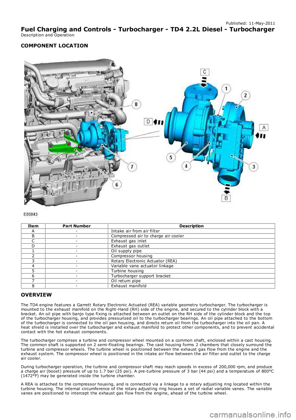
COMPONENT LOCATION
ItemPart NumberDescription
A-Int ake ai r from ai r fi lt erB-Compres sed ai r to charge air cool er
C-Exhaus t gas inlet
D-Exhaus t gas out let1-Oil s uppl y pipe
2-Compres sor housi ng
3-Rot ary El ect roni c Act uator (REA)4-Variable vane act uat or li nkage
5-Turbine hous ing
6-Turbocharger s upport bracket7-Oil ret urn pipe
8-Exhaus t manifol d
OVERVIEW
The TD4 engine feat ures a Garret t Rotary Electroni c Actuated (REA) variabl e geomet ry turbocharger. The t urbocharger i smounted t o t he exhaus t manifold on the Ri ght -Hand (RH) s ide of t he engine, and secured t o t he cyl inder block wit h abracket . An oil pi pe wit h banjo type fixing i s att ached bet ween an outl et on the RH s ide of t he cyl inder bl ock and the t opof the turbocharger hous ing, and provides pres s uri zed oi l to the t urbocharger beari ngs. An oi l pipe at tached to the bot tomof the turbocharger is connect ed to the oi l pan hous ing, and direct s ret urn oi l from t he t urbocharger i nt o t he oil pan. Aheat shi el d i s ins tal led over the t urbocharger and exhaust mani fold to protect other component s, and t o prevent acci dent alcont act wit h the hot exhaus t component s .
The t urbocharger compri ses a turbi ne and compres sor wheel mounted on a common s haft, enclos ed wit hin a cas t hous ing.The common s haft i s s upport ed on 2 semi -float ing beari ngs . The cast hous ing forms 2 chambers that clos ely s urround thet urbine and compres s or wheel s. The t urbine wheel i s pos i ti oned bet ween the exhaust gas flow from t he engine and t heexhaus t s ys t em. The compress or wheel is pos it ioned in the i ntake air flow bet ween t he air filt er and out let t o t he chargeair cooler.
Duri ng turbocharger operati on, t he t urbine and compres s or s haft may reach s peeds in exces s of 200,000 rpm, and producea charge ai r (boost ) pres s ure of up t o 1.7 bar (25 ps i). A pre-t urbine press ure of 3 bar (44 ps i) and a temperat ure of 800°C(1472°F) may be generated i nsi de t he turbi ne chamber.
A REA is at tached to the compres s or hous ing, and is connect ed via a li nkage t o a rotary adjus ti ng ri ng located wit hi n t het urbine hous ing. The internal circumference of t he rot ary adjus t ing ring hous es a s et of radial variable vanes . The variablevanes are pos it ioned to int ercept t he exhaus t gas fl ow from the engine, ahead of the t urbi ne wheel .
Page 1043 of 3229
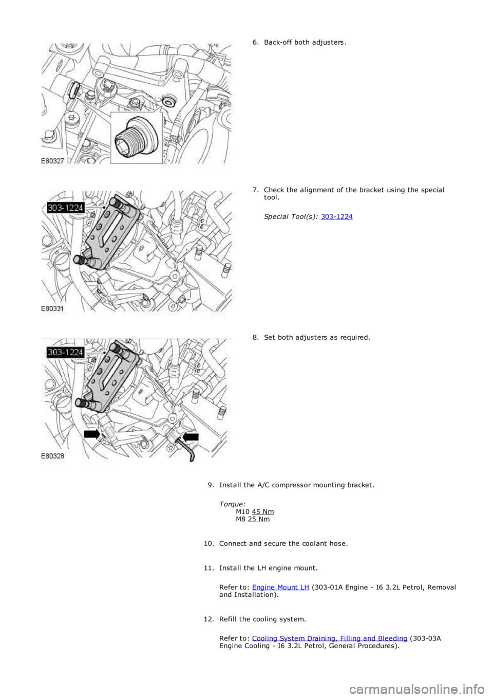
Back-off both adjus ters .
6. Check the al ignment of the bracket usi ng t he special
t ool .
Speci al Tool (s ): 303-1224 7.
Set both adjus t ers as requi red.
8.
Inst all t he A/C compress or mounti ng bracket .
T orque: M10 45 Nm M8
25 Nm 9.
Connect and s ecure t he cool ant hos e.
10.
Inst all t he LH engine mount.
Refer t o: Engi ne Mount LH (303-01A Engine - I6 3.2L Petrol, Removal
and Inst all at ion).
11.
Refi ll t he cool ing s yst em.
Refer t o: Cool ing Sys tem Drai ni ng, Fi lli ng and Bleeding (303-03A
Engine Cooli ng - I6 3.2L Petrol, General Procedures).
12.
Page 1079 of 3229
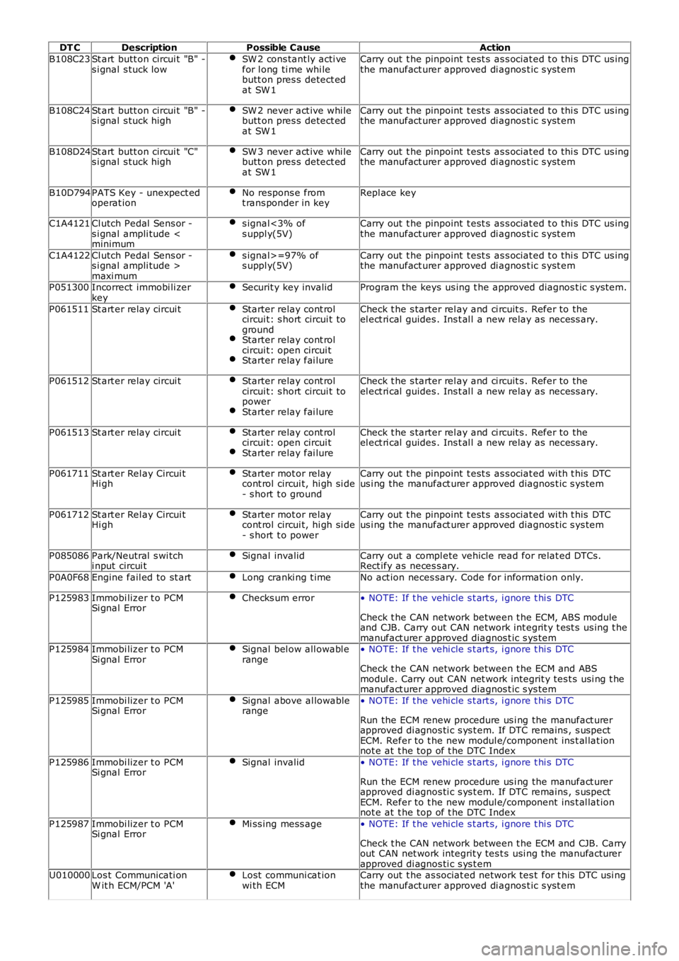
DT CDescriptionPossible CauseAction
B108C23St art butt on circui t "B" -s i gnal s tuck lowSW 2 cons tant ly acti vefor l ong ti me whi lebutt on pres s detect edat SW 1
Carry out t he pinpoint t est s as s ociat ed t o t hi s DTC us ingthe manufact urer approved di agnos t ic s yst em
B108C24St art butt on circui t "B" -s i gnal s tuck highSW 2 never act ive whi lebutt on pres s detect edat SW 1
Carry out t he pinpoint t est s as s ociat ed t o t hi s DTC us ingthe manufact urer approved di agnos t ic s yst em
B108D24St art butt on circui t "C"s i gnal s tuck highSW 3 never act ive whi lebutt on pres s detect edat SW 1
Carry out t he pinpoint t est s as s ociat ed t o t hi s DTC us ingthe manufact urer approved di agnos t ic s yst em
B10D794PATS Key - unexpect edoperat ionNo respons e fromt rans ponder in keyRepl ace key
C1A4121Cl utch Pedal Sens or -s i gnal ampli tude
C1A4122Cl utch Pedal Sens or -s i gnal ampli tude >maxi mum
s ignal>=97% ofs uppl y(5V)Carry out t he pinpoint t est s as s ociat ed t o t hi s DTC us ingthe manufact urer approved di agnos t ic s yst em
P051300Incorrect immobi li zerkeySecurit y key invalidProgram the keys us ing t he approved diagnos t ic s yst em.
P061511St art er relay circui tStarter relay cont rolcircui t: s hort circui t togroundStarter relay cont rolcircui t: open circui tStarter relay fai lure
Check t he s tarter rel ay and ci rcuit s . Refer to theel ect ri cal guides . Ins t al l a new relay as neces s ary.
P061512St art er relay circui tStarter relay cont rolcircui t: s hort circui t topowerStarter relay fai lure
Check t he s tarter rel ay and ci rcuit s . Refer to theel ect ri cal guides . Ins t al l a new relay as neces s ary.
P061513St art er relay circui tStarter relay cont rolcircui t: open circui tStarter relay fai lure
Check t he s tarter rel ay and ci rcuit s . Refer to theel ect ri cal guides . Ins t al l a new relay as neces s ary.
P061711St art er Rel ay Circui tHi ghStarter mot or relaycont rol circui t, hi gh si de- s hort t o ground
Carry out t he pinpoint t est s as s ociat ed wi th t his DTCus i ng the manufact urer approved diagnos t ic s ys tem
P061712St art er Rel ay Circui tHi ghStarter mot or relaycont rol circui t, hi gh si de- s hort t o power
Carry out t he pinpoint t est s as s ociat ed wi th t his DTCus i ng the manufact urer approved diagnos t ic s ys tem
P085086Park/Neutral s wi tchi nput circui tSignal invalidCarry out a compl ete vehicle read for relat ed DTCs.Rect ify as neces s ary.
P0A0F68Engine fail ed to st artLong cranki ng t imeNo act ion neces sary. Code for informati on only.
P125983Immobi lizer t o PCMSi gnal ErrorChecks um error• NOTE: If t he vehi cle s t art s, i gnore t hi s DTC
Check t he CAN network between t he ECM, ABS moduleand CJB. Carry out CAN network int egrit y t est s us ing t hemanufact urer approved diagnos t ic s ys temP125984Immobi lizer t o PCMSi gnal ErrorSignal bel ow all owabl erange• NOTE: If t he vehi cle s t art s, i gnore t hi s DTC
Check t he CAN network between t he ECM and ABSmodul e. Carry out CAN net work integrit y tes t s usi ng t hemanufact urer approved diagnos t ic s ys tem
P125985Immobi lizer t o PCMSi gnal ErrorSignal above al lowablerange• NOTE: If t he vehi cle s t art s, i gnore t hi s DTC
Run the ECM renew procedure us i ng the manufact urerapproved di agnos ti c s ys t em. If DTC remains , s uspectECM. Refer to t he new modul e/component ins t al lat ionnot e at t he top of t he DTC Index
P125986Immobi lizer t o PCMSi gnal ErrorSignal invalid• NOTE: If t he vehi cle s t art s, i gnore t hi s DTC
Run the ECM renew procedure us i ng the manufact urerapproved di agnos ti c s ys t em. If DTC remains , s uspectECM. Refer to t he new modul e/component ins t al lat ionnot e at t he top of t he DTC Index
P125987Immobi lizer t o PCMSi gnal ErrorMi ss ing mess age• NOTE: If t he vehi cle s t art s, i gnore t hi s DTC
Check t he CAN network between t he ECM and CJB. Carryout CAN net work integrit y tes t s usi ng t he manufacturerapproved di agnos ti c s ys t emU010000Los t Communicati onW it h ECM/PCM 'A'Lost communi cat ionwi th ECMCarry out t he as sociat ed network tes t for t his DTC usi ngthe manufact urer approved di agnos t ic s yst em
Page 1087 of 3229
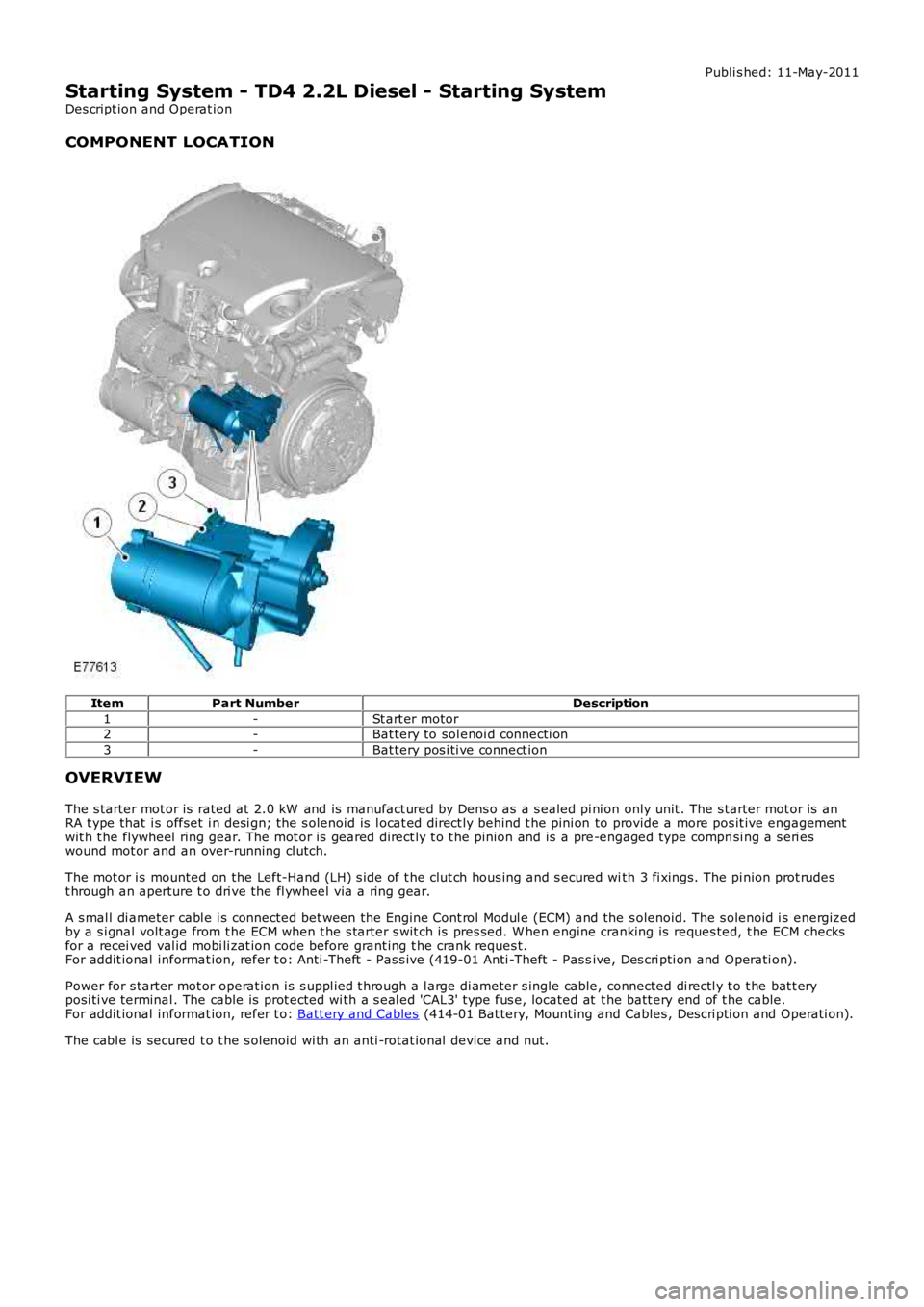
Publi s hed: 11-May-2011
Starting System - TD4 2.2L Diesel - Starting System
Des cript ion and Operat ion
COMPONENT LOCATION
ItemPart NumberDescription
1-St art er motor2-Bat tery to sol enoi d connecti on
3-Bat tery pos i ti ve connect ion
OVERVIEW
The s tarter mot or is rated at 2.0 kW and is manufact ured by Dens o as a s ealed pi ni on only unit . The s tarter mot or is anRA t ype that i s offset i n desi gn; the s olenoid is l ocat ed direct ly behind t he pini on to provide a more pos it ive engagementwit h t he flywheel ring gear. The mot or is geared direct ly t o t he pinion and is a pre-engaged type compri si ng a s eri eswound mot or and an over-running cl utch.
The mot or i s mounted on the Left-Hand (LH) s ide of t he clut ch hous ing and s ecured with 3 fi xings. The pi nion prot rudest hrough an aperture t o dri ve the fl ywheel via a ri ng gear.
A s mal l di ameter cabl e i s connected bet ween the Engine Cont rol Modul e (ECM) and the s olenoid. The s olenoid i s energizedby a s i gnal volt age from t he ECM when t he s tarter s wit ch is pres sed. W hen engine cranking is reques ted, t he ECM checksfor a recei ved val id mobi li zat ion code before grant ing t he crank reques t.For addit ional informat ion, refer t o: Anti -Theft - Pas s ive (419-01 Anti -Theft - Pas sive, Des cri pti on and Operati on).
Power for s tarter mot or operat ion i s s uppl ied t hrough a l arge di ameter s ingle cable, connected di rectl y t o t he bat t eryposi ti ve terminal . The cable is prot ected wi th a s eal ed 'CAL3' type fus e, located at t he batt ery end of t he cable.For addit ional informat ion, refer t o: Batt ery and Cables (414-01 Bat tery, Mounti ng and Cables , Des cri pti on and Operati on).
The cabl e is secured t o t he s olenoid wi th an anti -rotat ional device and nut.
Page 1105 of 3229
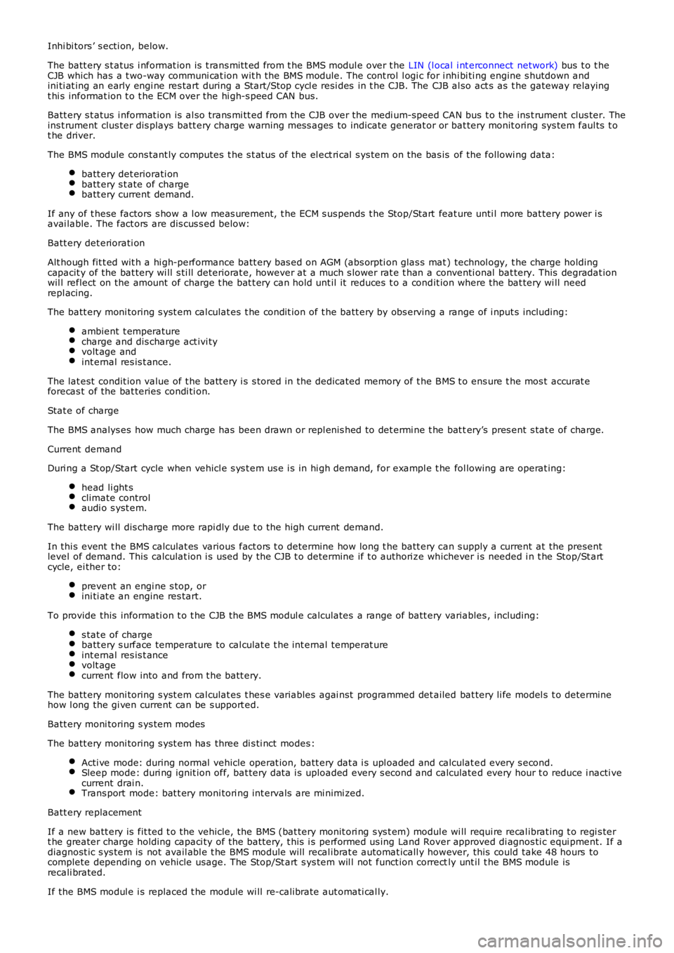
Inhi bi tors ’ s ecti on, below.
The batt ery s t atus i nformat ion is t rans mit t ed from t he BMS modul e over t he LIN (l ocal i nt erconnect network) bus t o t heCJB which has a t wo-way communi cat ion wit h the BMS module. The cont rol l ogi c for i nhi bi ti ng engine s hutdown andini ti at ing an early engi ne res tart during a Start/Stop cycl e resi des in t he CJB. The CJB al so act s as t he gateway relayingt hi s informat ion t o t he ECM over the hi gh-s peed CAN bus.
Batt ery s t atus i nformat ion is al so trans mi tt ed from the CJB over the medi um-speed CAN bus t o t he ins t rument clus ter. Theins t rument clus ter dis plays batt ery charge warning mes s ages to indicate generat or or bat tery monit oring sys tem faul ts t ot he driver.
The BMS module cons tant ly computes t he s t at us of the el ect ri cal s ys tem on the bas is of the followi ng data:
batt ery det eriorati onbatt ery s t ate of chargebatt ery current demand.
If any of t hese factors s how a l ow meas urement, t he ECM s us pends t he Stop/Start feature unti l more bat tery power i savai lable. The fact ors are dis cus s ed below:
Batt ery det eriorati on
Alt hough fit t ed wit h a hi gh-performance batt ery bas ed on AGM (abs orpti on glas s mat ) technol ogy, t he charge holdingcapacit y of the bat tery wi ll s ti ll deteriorat e, however at a much s lower rat e t han a conventi onal bat tery. This degradat ionwil l reflect on the amount of charge t he bat t ery can hold unt il it reduces t o a condit ion where the bat tery wi ll needrepl acing.
The batt ery moni toring s yst em cal culat es t he condit ion of t he batt ery by obs erving a range of i nput s including:
ambient t emperaturecharge and dis charge act ivi tyvolt age andint ernal res is t ance.
The lat est condit ion value of t he batt ery i s s tored in the dedicated memory of t he BMS t o ens ure t he mos t accurat eforecas t of the bat teries condi ti on.
Stat e of charge
The BMS analys es how much charge has been drawn or repl enis hed to det ermi ne t he bat tery’s pres ent s tat e of charge.
Current demand
Duri ng a St op/Start cycle when vehicl e s ys t em us e i s in hi gh demand, for exampl e t he fol lowing are operat ing:
head li ght sclimate controlaudi o s yst em.
The batt ery wi ll dis charge more rapi dly due t o t he high current demand.
In thi s event t he BMS calculat es various fact ors t o determine how long t he batt ery can s upply a current at the presentlevel of demand. This calculat ion i s used by the CJB t o determine if t o authori ze whichever i s needed i n t he Stop/St artcycle, ei ther to:
prevent an engi ne s top, orini ti at e an engine res tart.
To provide this informati on t o t he CJB the BMS modul e calculates a range of batt ery variables , including:
s tat e of chargebatt ery s urface temperat ure to cal culat e t he int ernal temperat ureint ernal res is t ancevolt agecurrent flow into and from t he batt ery.
The batt ery moni toring s yst em cal culat es t hes e vari abl es agai nst programmed det ailed bat tery li fe model s t o determinehow l ong the gi ven current can be s upport ed.
Batt ery moni toring s ys tem modes
The batt ery moni toring s yst em has three di s ti nct modes :
Acti ve mode: during normal vehicle operat ion, batt ery dat a i s upl oaded and calculat ed every s econd.Sleep mode: duri ng ignit ion off, bat tery dat a i s uploaded every s econd and calculated every hour t o reduce i nacti vecurrent drai n.Trans port mode: bat t ery moni tori ng int ervals are mi nimi zed.
Batt ery replacement
If a new batt ery is fit ted t o t he vehicle, the BMS (bat tery monit ori ng s ys t em) module wi ll requi re recal ibrat ing t o regi s tert he greater charge holding capaci ty of the bat tery, t his i s performed us ing Land Rover approved di agnos ti c equi pment. If adiagnost ic s ys tem is not avail abl e t he BMS module will recal ibrat e automat icall y however, this could take 48 hours tocomplete depending on vehicle usage. The Stop/St art s ys tem wil l not funct ion correctly unt il t he BMS module isrecali brated.
If the BMS modul e i s replaced t he module wi ll re-calibrate aut omati cal ly.
Page 1110 of 3229
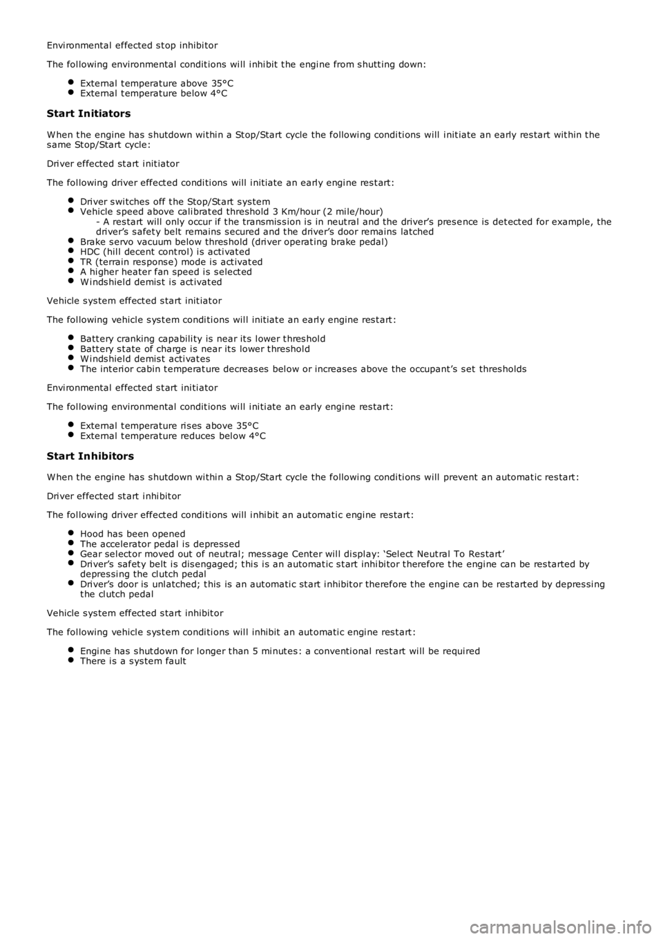
Envi ronmental effected s t op inhibi tor
The fol lowing environmental condit ions wi ll i nhi bit t he engi ne from s hutt ing down:
External t emperature above 35°CExternal t emperature below 4°C
Start Initiators
W hen t he engine has s hutdown wi thi n a St op/Start cycle the followi ng condi ti ons will i nit iate an early res tart wit hin t hes ame St op/Start cycle:
Dri ver effected st art i nit iator
The fol lowing driver effect ed condi ti ons will i nit iate an earl y engi ne res t art:
Dri ver s wi tches off t he Stop/St art s ys temVehicle s peed above cali brat ed threshold 3 Km/hour (2 mi le/hour)- A res tart will only occur if t he transmis s ion i s in neut ral and the driver’s pres ence is det ect ed for example, thedri ver’s s afet y belt remains s ecured and t he driver’s door remains latchedBrake s ervo vacuum below thres hold (dri ver operat ing brake pedal)HDC (hil l decent cont rol) i s acti vat edTR (terrain res pons e) mode i s act ivat edA hi gher heater fan speed i s s elect edW i nds hiel d demis t i s act ivat ed
Vehicle s ys tem effect ed s tart init iat or
The fol lowing vehicl e s ys t em condi ti ons wil l init iat e an earl y engine res t art :
Batt ery cranking capabili ty is near it s l ower t hres hol dBatt ery s t ate of charge i s near it s lower t hreshol dW i nds hiel d demis t acti vat esThe int eri or cabin t emperat ure decreas es bel ow or increas es above the occupant’s s et thres holds
Envi ronmental effected s t art ini ti ator
The fol lowing environmental condit ions wi ll i ni ti ate an early engi ne res tart:
External t emperature ri s es above 35°CExternal t emperature reduces bel ow 4°C
Start Inhibitors
W hen t he engine has s hutdown wi thi n a St op/Start cycle the followi ng condi ti ons will prevent an automat ic res tart :
Dri ver effected st art i nhi bit or
The fol lowing driver effect ed condi ti ons will i nhi bit an aut omati c engi ne res tart:
Hood has been openedThe accelerator pedal i s depress edGear sel ect or moved out of neutral; mes s age Cent er wil l di spl ay: ‘Sel ect Neut ral To Res tart ’Dri ver’s safet y belt i s dis engaged; t hi s i s an automat ic s t art inhi bi tor t herefore the engi ne can be res tarted bydepres si ng the cl utch pedalDri ver’s door is unl atched; t his is an aut omati c st art i nhibit or therefore t he engine can be rest art ed by depres si ngt he cl utch pedal
Vehicle s ys tem effect ed s tart inhibit or
The fol lowing vehicl e s ys t em condi ti ons wil l inhibit an aut omati c engi ne res t art :
Engi ne has s hut down for l onger t han 5 mi nut es : a conventi onal res t art wi ll be requi redThere i s a s ys tem fault