Page 784 of 3229
The cyl inder head and st ructural cams haft cover are manufactured to form mat ing parts . The part s are mil led i n a si ngl eoperati on and accurat ely pos it ioned wi th 2 alignment s leeves. The 2 components mus t al ways be ins tall ed t oget her, andnot renewed as s eparate component s . The cyl inder head and cams haft cover are s eal ed to each ot her during manufact urewit h a gas ket and s ili cone bas ed s eal ant, and are s ecured wit h 27 bolt s . An oil s eal i nst all ed at the front of t he cyl inderhead provides s eal ing of t he exhaus t camshaft hous ing. The open port s at the rear of the cyli nder head are sealed wit ht he vacuum pump and hi gh-pres s ure fuel pump s eal ing rings .
Two ali gnment sl eeves correct ly l ocat e t he cyl inder head and gas ket to t he cylinder block. The cyli nder head is secured t ot he cyl inder bl ock wit h 10 deep-s eat ed bolt s .
• NOTE: The cyl inder head bol ts are not acces si ble wit h the st ruct ural cams haft cover i nst all ed.
• NOTE: The cyl inder head is not t o be reworked.
The cyl inder head is manufact ured from al uminum alloy, havi ng valve s eats and guides made of s i nt ered st eel. Thecyl inder head is precis ely machi ned and mil led t o i ncorporate t he 4 combus ti on chambers, cams haft l ower beari nghous i ngs , oil drill ings and cool ant gal leri es, and t he air i ntake, val ve ti ming and fuel sys t em component bores andhous i ngs .
The desi gn of the cyli nder head maximizes air flow and s wi rl i n the combus ti on chambers. The 2 int ake val ve seat s aremachined wit h rais ed profil es that act to promote swi rl of t he int ake ai r fl ow. Combined wit h t he acti on of the i ntakemanifold heli cal port , t he s wirl effect of the 2 int ake port profi les al lows t he air and i nject ed fuel t o complet el y mi x, andreach t he outer edge of the combus ti on chamber.
The s truct ural camshaft cover is manufact ured from alumi num all oy, and i s machined on t he upper s urface wit h t hecamshaft upper bearing hous ings . The cover is al so formed wi th 4 int ake ai r fi ll ing t racts , fuel i nject or bores and ori fi cesfor t he cyl inder head cover PCV components . The i nt ake air t racts join the i ntake air mani fold to the cyli nder head int akefi ll ing port s .
The cyl inder head al s o provides t he mounti ng locati ons for the foll owing:
Front engi ne mounti ngFront and rear engine l ifti ng eyesInt ake and exhaus t manifol dsEGR valve and coolerFuel fil ter s upport bracketThermal cont rol moduleVacuum pump and high-press ure fuel pump.
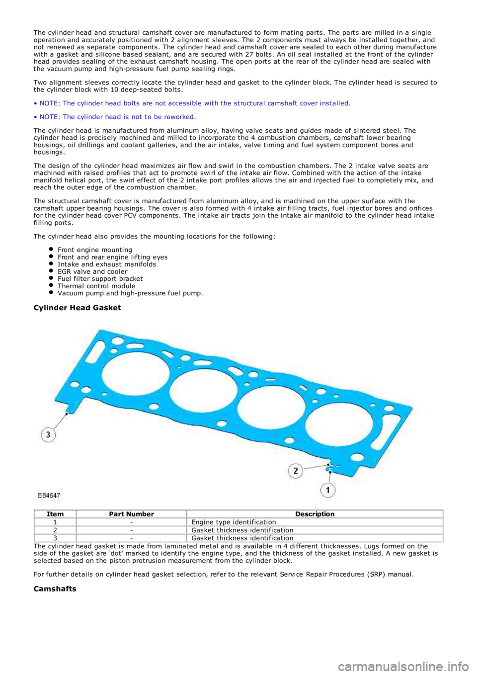
Cylinder Head G asket
ItemPart NumberDescription
1-Engi ne type i dent ificati on
2-Gas ket thi cknes s identi fi cat ion3-Gas ket thi cknes s identi fi cat ion
The cyl inder head gas ket is made from l aminated metal and is avail abl e i n 4 di fferent thickness es . Lugs formed on thes ide of t he gasket are 'dot' marked to i dent ify t he engi ne t ype, and t he thi ckness of t he gas ket i nst all ed. A new gasket iss elect ed bas ed on t he pis ton protrusi on meas urement from t he cyl inder block.
For furt her det ail s on cyl inder head gas ket sel ect ion, refer t o t he rel evant Servi ce Repair Procedures (SRP) manual .
Camshafts
Page 790 of 3229
ItemPart NumberDescription
1-Thermal control modul e2-Securi ng bol t (2 off)
3-Securi ng s tud and nut (2 off)
The cool ing s ys tem thermal control modul e i s s ecured to t he rear of t he cyl inder head by 2 s tuds wi th nut s and 2 bol ts ,and is sealed to the head wi th an O-ring. The module contai ns the cooli ng s ys t em t hermos tat and forms the junct ion fort he cooli ng s yst em hos es.For addit ional informat ion, refer t o: Engi ne Cooling (303-03B Engine Cooli ng - TD4 2.2L Dies el , Descripti on and Operat ion).
Vacuum Pump
Page 793 of 3229
ItemPart NumberDescription
1-High-pres sure common fuel rail2-Bolt (2 off)
The common fuel rail is manufact ured from forged s teel and is s ecured wi th 2 bolt s to the cyli nder head, above t he li ne oft he exhaus t cams haft . The fuel rai l st ores press uri zed fuel from t he high-pres sure fuel pump and deli vers t he fuel t o thefuel inject ors .
The fuel rai l pres sure is regulat ed by a Pres s ure Cont rol Valve (PCV) l ocat ed at the fuel pump end of the fuel rail , undert he cont rol of the ECM. A fuel pres sure s ensor i ns t alled in t he oppos i te end of t he fuel rai l provides t he act ual fuelpres s ure s ignal to the ECM. For addi ti onal i nformat ion, refer to:
Fuel Charging and Cont rols (303-04B Fuel Charging and Controls - TD4 2.2L Di es el, Des cri pt ion and Operati on),Elect roni c Engi ne Cont rol s (303-14 Electroni c Engi ne Controls - 2.2L Duratorq - Td4, Descri pti on and Operat ion).
Fuel Injectors
Page 794 of 3229
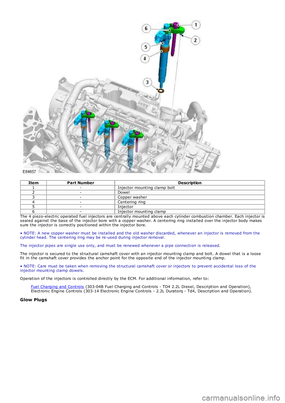
ItemPart NumberDescription
1-Injector mount ing clamp bol t2-Dowel
3-Copper washer
4-Cent ering ring5-Injector
6-Injector mount ing clamp
The 4 pi ezo-el ect ri c operated fuel injectors are cent rall y mounted above each cyl inder combus ti on chamber. Each i njector iss eal ed agai nst the bas e of the injector bore wit h a copper was her. A cent ering ri ng ins tal led over the i njector body makess ure t he i nject or is correct ly pos i ti oned wi thi n t he inject or bore.
• NOTE: A new copper washer mus t be i ns t alled and the ol d was her dis carded, whenever an inject or is removed from t hecyl inder head. The cent eri ng ri ng may be re-us ed duri ng inject or removal.
The inject or pi pes are s i ngl e us e only, and mus t be renewed whenever a pi pe connection is releas ed.
The inject or is s ecured t o t he st ruct ural cams haft cover wit h an i nject or mounti ng cl amp and bolt . A dowel that i s a l oos efi t in the cams haft cover provi des the anchor point for the opposi te end of the i njector mounti ng clamp.
• NOTE: Care must be taken when removi ng the st ruct ural cams haft cover or i njectors to prevent acci dent al los s of theinject or mount ing cl amp dowels .
Operat ion of t he inject ors i s cont rol led direct ly by the ECM. For addi ti onal i nformat ion, refer to:
Fuel Charging and Cont rols (303-04B Fuel Charging and Controls - TD4 2.2L Di es el, Des cri pt ion and Operati on),Elect roni c Engi ne Cont rol s (303-14 Electroni c Engi ne Controls - 2.2L Duratorq - Td4, Descri pti on and Operat ion).
Glow Plugs
Page 796 of 3229
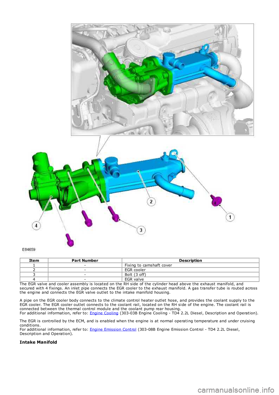
ItemPart NumberDescription
1-Fixi ng to cams haft cover2-EGR cooler
3-Bolt (3 off)
4-EGR valveThe EGR valve and cooler ass embl y is l ocat ed on t he RH s ide of t he cylinder head above t he exhaus t manifold, ands ecured wit h 4 fixi ngs . An i nl et pipe connects the EGR cooler t o t he exhaus t manifold. A gas t rans fer t ube is rout ed acros st he engi ne and connect s t he EGR valve out let t o the intake mani fold hous ing.
A pi pe on t he EGR cool er body connect s to the cl imat e cont rol heater outl et hos e, and provides t he cool ant s upply t o t heEGR cooler. The EGR cooler outl et connect s t o t he cool ant rail , locat ed on t he RH s ide of the engine. The cool ant rail isconnected bet ween the t hermal control modul e and the coolant pump rear hous ing.For addit ional informat ion, refer t o: Engi ne Cooling (303-03B Engine Cooli ng - TD4 2.2L Dies el , Descripti on and Operat ion).
The EGR i s cont rol led by t he ECM, and is enabled when t he engine i s at normal operati ng t emperature and under crui si ngcondi ti ons .For addit ional informat ion, refer t o: Engi ne Emis s ion Cont rol (303-08B Engi ne Emis s ion Cont rol - TD4 2.2L Di esel ,Des cript ion and Operat ion).
Intake Manifold
Page 800 of 3229
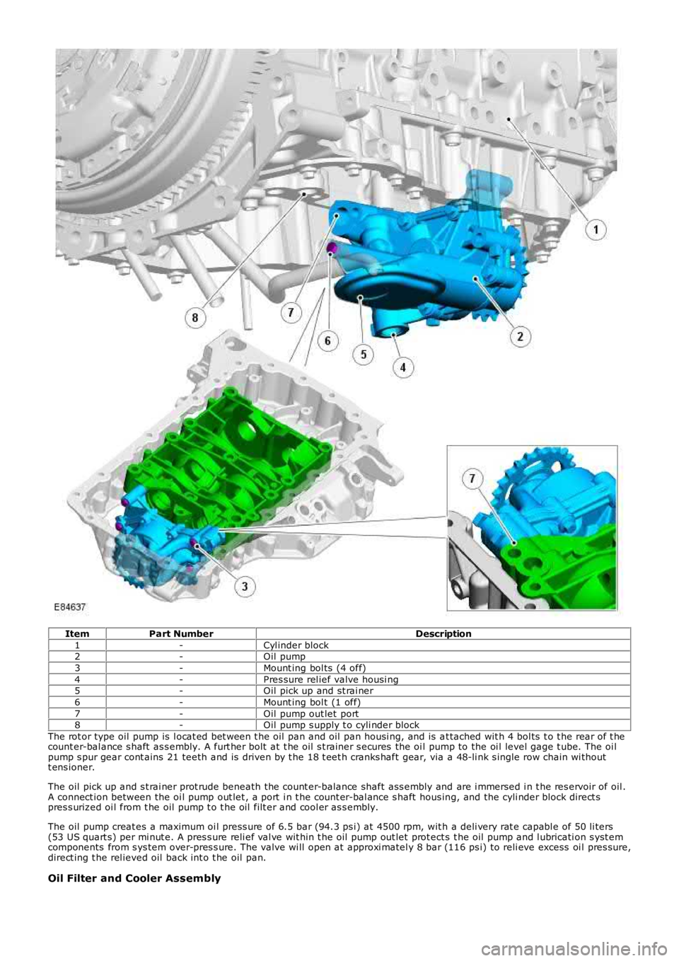
ItemPart NumberDescription
1-Cyl inder block2-Oil pump
3-Mount ing bol ts (4 off)
4-Pres sure rel ief valve housi ng5-Oil pick up and st rai ner
6-Mount ing bol t (1 off)
7-Oil pump out let port8-Oil pump s upply t o cyli nder block
The rot or type oil pump is l ocat ed bet ween t he oil pan and oil pan housi ng, and is at tached wit h 4 bol ts t o t he rear of t hecount er-bal ance s haft as s embly. A furt her bolt at t he oil s t rainer s ecures the oi l pump to the oi l level gage t ube. The oi lpump s pur gear cont ains 21 teeth and is driven by t he 18 t eet h cranks haft gear, via a 48-li nk s ingle row chain wi thoutt ens ioner.
The oil pick up and s t rai ner prot rude beneath the count er-balance shaft ass embly and are i mmersed i n t he res ervoir of oil .A connect ion between the oi l pump out let , a port i n t he count er-bal ance s haft hous ing, and the cyli nder block direct spres s urized oi l from t he oil pump t o t he oil filt er and cool er as s embly.
The oil pump creat es a maximum oi l press ure of 6.5 bar (94.3 ps i) at 4500 rpm, wit h a deli very rat e capabl e of 50 li ters(53 US quart s) per mi nut e. A pres s ure reli ef val ve wit hin t he oil pump out let prot ect s t he oil pump and l ubricati on s yst emcomponents from s ys tem over-pres s ure. The valve wi ll open at approxi matel y 8 bar (116 ps i) to reli eve excess oi l pres sure,direct ing t he rel ieved oil back int o t he oil pan.
Oil Filter and Cooler Assembly
Page 822 of 3229
"Make s ure t hat a new component i s ins t al led. "
Make s ure that t he mat ing faces are clean and free of foreign
mat eri al .
Inst all t he EGR pipe.
T orque: 10 Nm At tach t he s pi ll ret urn li ne.
11.
Connect and s ecure t he fuel inject or wiring harnes s electrical
connectors.
T orque: 10 Nm 12.
Inst all t he breather li ne.
13.
Inst all t he fuel fi lt er.
Refer t o: Fuel Fil ter (310-01B Fuel Tank and Lines - TD4 2.2L Dies el ,
Removal and Ins tall ati on).
14.
Connect t he batt ery ground cable.
Refer t o: Specificati ons (414-00 Bat tery and Charging Sys tem -
General Informat ion, Specificati ons).
15.
Page 841 of 3229
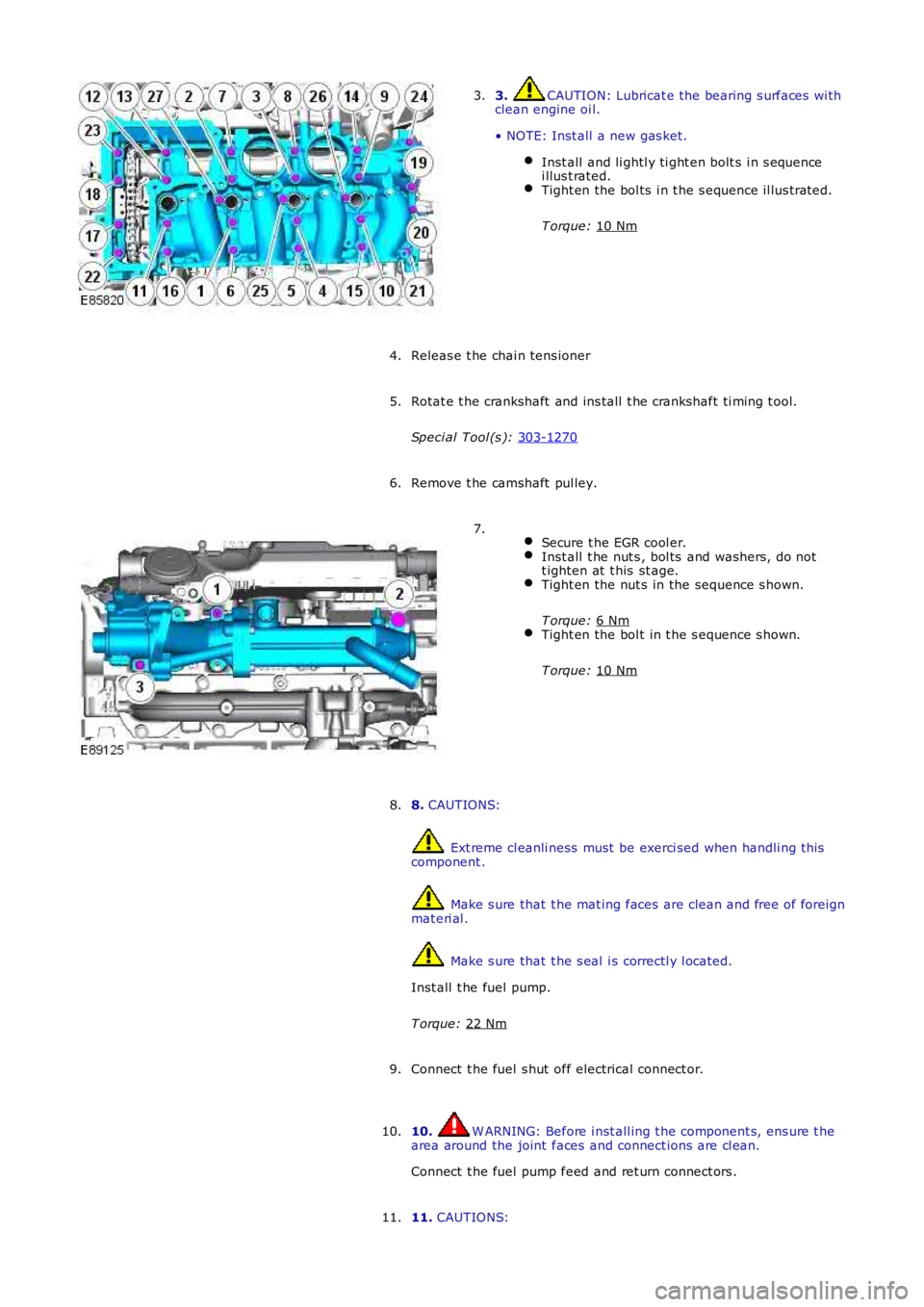
3. CAUTION: Lubricat e the bearing s urfaces wi th
clean engine oi l.
• NOTE: Inst all a new gas ket. Inst all and li ghtl y ti ght en bolt s i n s equence
i llus t rated. Tight en the bol ts i n t he s equence il lus trated.
T orque: 10 Nm 3.
Releas e t he chai n tens ioner
4.
Rotat e t he crankshaft and ins tall t he crankshaft ti ming t ool.
Speci al Tool (s ): 303-1270 5.
Remove t he camshaft pul ley.
6.
Secure t he EGR cool er. Inst all t he nut s , bol ts and washers, do not
t ighten at t his st age. Tight en the nut s in the sequence s hown.
T orque: 6 Nm Tight en the bol t in t he s equence s hown.
T orque: 10 Nm 7.
8. CAUTIONS: Ext reme cl eanli ness must be exerci sed when handli ng t hi s
component . Make s ure that t he mat ing faces are clean and free of foreign
mat eri al . Make s ure that t he s eal i s correctl y l ocated.
Inst all t he fuel pump.
T orque: 22 Nm 8.
Connect t he fuel s hut off electrical connect or.
9.
10. W ARNING: Before i nst all ing t he component s, ens ure t he
area around the joint faces and connect ions are cl ean.
Connect t he fuel pump feed and ret urn connect ors .
10.
11. CAUTIONS:
11.