Page 630 of 3229

5-Bolt (2 of)6-Variable tract valveThe intake manifold att aches t o t he cylinder head wit h 6 bolt s and t he oil pan with 2 bolt s .
The manifold is capable of varying both int ake tract length and plenum volume by means of 2 separat e valves .
At low engine s peeds , long int ake tract s are ut iliz ed to provide opt imum engine t orque. Short er t racts are us ed at medium s peeds ,again, t o optimiz e engine t orque for t he exist ing engine s peed range.
At higher engine s peeds the benefit s of opt imizing t he t ract lengt hs are outweighed by the necess it y of maintaining anappropriate supply of air to meet t he engines requirement s . Therefore, t he plenum valve is opened t o create a s ingle, largeplenum volume to provide t he maximum quant ity of air t o charge the engines cylinders.For addit ional information, refer t o: Int ake Air Dis tribut ion and Filtering (303-12A Int ake Air Dis t ribution and Filt ering - I6 3.2LPet rol, Des cript ion and O perat ion).
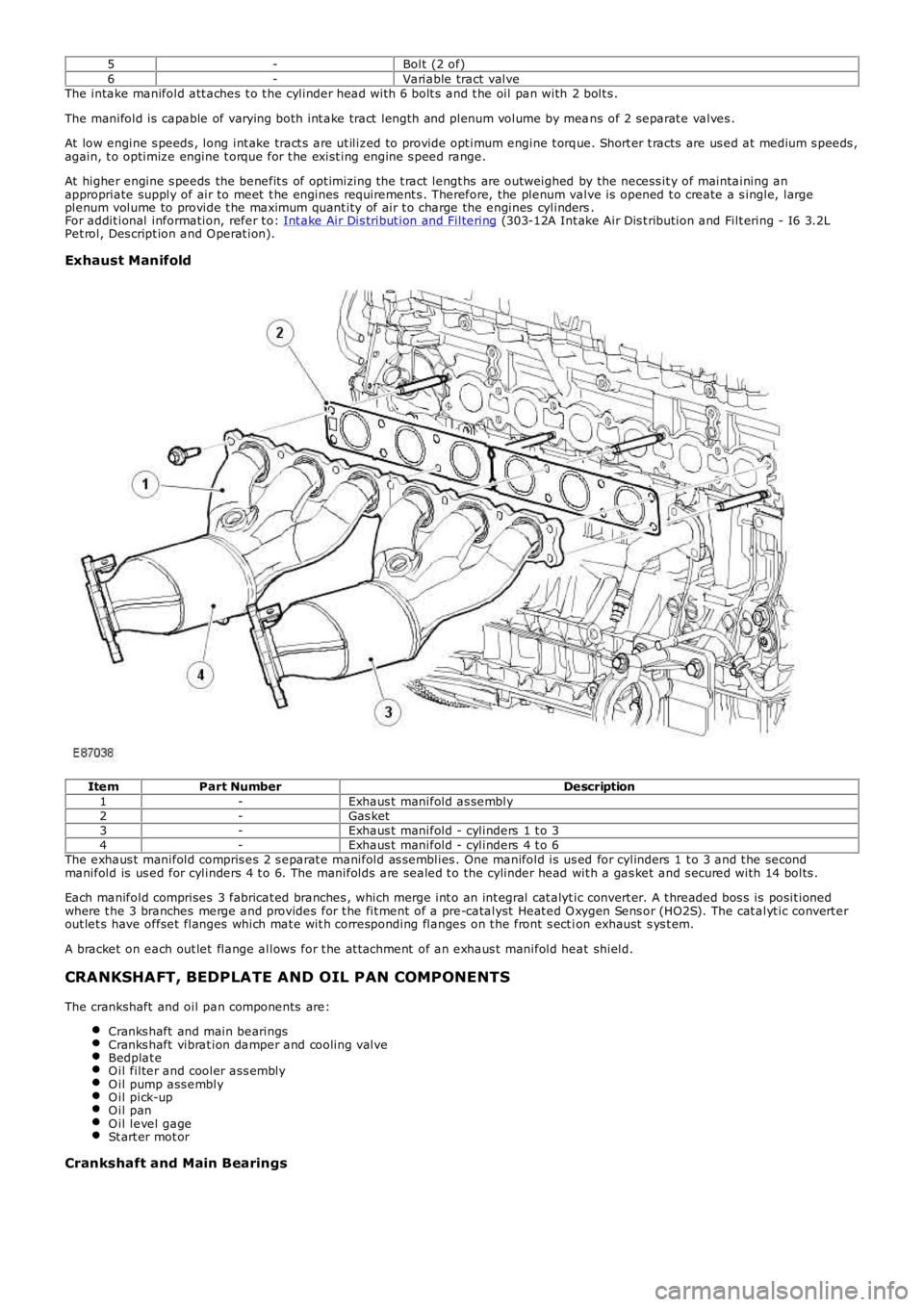
Exhaust Manifold
ItemPart NumberDescription1-Exhaus t manifold as sembly2-Gas ket3-Exhaus t manifold - cylinders 1 t o 34-Exhaus t manifold - cylinders 4 t o 6The exhaus t manifold compris es 2 s eparat e manifold as semblies . One manifold is us ed for cylinders 1 t o 3 and t he secondmanifold is us ed for cylinders 4 t o 6. The manifolds are sealed t o the cylinder head wit h a gas ket and s ecured with 14 bolts .
Each manifold comprises 3 fabricat ed branches , which merge int o an int egral cat alyt ic convert er. A t hreaded bos s is posit ionedwhere t he 3 branches merge and provides for t he fit ment of a pre-catalyst Heat ed O xygen Sens or (HO2S). The cat alyt ic convert erout let s have offset flanges which mat e wit h corresponding flanges on t he front s ect ion exhaust s ys t em.
A bracket on each out let flange allows for t he at t achment of an exhaus t manifold heat shield.
CRANKSHAFT, BEDPLATE AND OIL PAN COMPONENTS
The crankshaft and oil pan components are:
Cranks haft and main bearingsCranks haft vibrat ion damper and cooling valveBedplat eO il filter and cooler ass emblyO il pump ass emblyO il pick-upO il panO il level gageSt art er mot or
Crankshaft and Main Bearings
Page 640 of 3229
ItemPart NumberDescription1-Oil level gage2-Oil level gage t ube3-Bolt4-O-ring s ealThe oil level gauge locat es along t he int ake s ide of t he engine and is s upport ed in a t ube ins t alled in t he oil pan. A bolt s ecurelyat t aches the t ube to t he engine oil cooler via a bracket . Two holes in t he end of t he gauge indicate the minimum and maximum oillevels . The difference between the dips t ick markings , minimum and maximum, corresponds t o 0.8 lit res .
Starter Motor
Page 652 of 3229

Publi s hed: 11-May-2011
Engine - I6 3.2L Petrol - Valve Clearance Adjustment
General Procedures
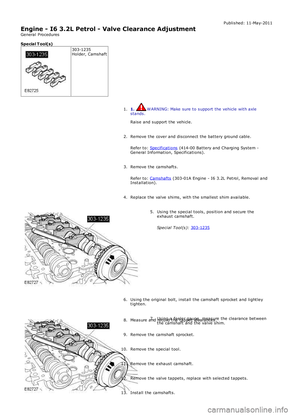
Special T ool(s) 303-1235
Hol der, Camshaft
1. W ARNING: Make sure t o s upport the vehicle wit h axle
s tands .
Rais e and s upport t he vehi cl e.
1.
Remove t he cover and dis connect the bat tery ground cabl e.
Refer t o: Specificati ons (414-00 Bat tery and Charging Sys tem -
General Informat ion, Specificati ons).
2.
Remove t he camshaft s .
Refer t o: Camshafts (303-01A Engine - I6 3.2L Pet rol , Removal and
Inst all at ion).
3.
Replace t he val ve s hi ms , wit h t he s mall es t s him avai lable.
4. Us ing t he s peci al t ools , posi ti on and s ecure the
exhaus t cams haft.
Speci al Tool (s ): 303-1235 5.
Us ing t he original bol t, i nst all t he camshaft sprocket and li ght ley
t ighten.
6. Us ing a feeler gauge, meas ure the cl earance bet ween
t he camshaft and the valve s him.
7.
Meas ure and record t he tappet cl earances .
8.
Remove t he camshaft sprocket.
9.
Remove t he s pecial t ool .
10.
Remove t he exhaus t cams haft .
11.
Remove t he val ve tappets , repl ace wit h s elect ed t appet s.
12.
Inst all t he camshaft s .
13.
Page 654 of 3229
Publi s hed: 11-May-2011
Engine - I6 3.2L Petrol - Valve Clearance Check
General Procedures
Special T ool(s) 303-1235
Hol der, Camshaft
• NOTE: Only the exhaus t cam shaft has adjus t abl e t appet s. 1. W ARNING: Make sure t o s upport the vehicle wit h axle
s tands .
Rais e and s upport t he vehi cl e.
1.
Remove t he cover and dis connect the bat tery ground cabl e.
Refer t o: Specificati ons (414-00 Bat tery and Charging Sys tem -
General Informat ion, Specificati ons).
2.
Remove t he camshaft bearing housi ng.
Refer t o: Val ve Cover (303-01A Engine - I6 3.2L Pet rol , Removal and
Inst all at ion).
3. Us ing t he s peci al t ools , posi ti on and s ecure the
exhaus t cams haft.
Speci al Tool (s ): 303-1235 4.
Us ing t he original bol t, i nst all t he camshaft sprocket and li ght ley
t ighten.
5.
For val ve cl earance dat a, refer t o s peci fi cat ions .
Refer t o: Specificati ons (303-01A Engine - I6 3.2L Petrol ,
Speci fi cat ions ).
6.
Page 663 of 3229
Remove and dis card t he i nt ake manifold gas ket s .
26.
Installation Clean t he component mat ing faces .
1.
Inst all t he gas kets .
2.
Inst all t he int ake mani fol d modules .
3.
Inst all t he MAP s ensor.
4.
Inst all t he purge valve as s embl y.
5. Inst all t he thrott le body and t ighten the s crews i n t he
s equence s hown.
T orque: 8 Nm 6.
Inst all t he inlet mani fold and ti ght en t he bolt s.
T orque: 16 Nm 7.
Inst all t he cool ing fan module.
8.
Connect t he cool ant bl eed hos e.
9.
Inst all t he PAS fl uid reservoi r in the bracket.
10.
Inst all t he dips ti ck.
11.
Connect and s ecure t he electrical connect ors .
12.
Inst all t he A/C li ne support bracket and ti ghten t he bolt .
13.
Page 670 of 3229
T orque:
16 Nm 9.
T orque:
16 Nm 10.
Install the l ifting brackets.
Torque: 48 Nm 11.
Secure t he cylinder head wiri ng harness.
12.
Page 671 of 3229

Torque:
6 Nm 13.
CAUTIONS: Extreme cleanli ness must be exerci sed when handli ng this component.
A new O-ring seal is t o be instal led.
Install the CPS solenoids.
Torque: 10 Nm 13.
Connect the CPS solenoi ds.
14.
15. CAUTIONS: Apply clean engi ne oil to t he VVT sol enoid shaft.
Extreme cleanli ness must be exerci sed when handli ng this component.
A new O-ring seal is t o be instal led.
Install the VVT solenoid.
Torque: 10 Nm 15.
Connect the VVT solenoid.
16.
Install the CMP sensors.
Torque: 10 Nm 17.
Connect and secure the CMP sensor electrical connectors.
18.
Connect the fuel i nj ector electrical connectors.
19.
Connect the ground cabl e.
Torque: 6 Nm 20.
Install the engine mount.
Refer to: Engine Mount RH (303-01A Engi ne - I6 3.2L Petrol, Removal and
Installation).
21.
Install the i gniti on coil-on-pl ugs.
Refer to: Igni tion Coil-On-Plug (303-07A Engine Igni tion, Removal and
Installation).
22.
Install the crankcase vent oil separator.
Refer to: Crankcase Vent Oi l Separator (303-08A Engine Emi ssi on Control - I6 3.2L
Petrol, Removal and Installation).
23.
Install the ti ming component housi ng.
Refer to: Timing Components Housing (303-01A Engine - I6 3.2L Pet rol , Removal
and Install ati on).
24.
Connect the battery ground cable and instal l the cover.
Refer to: Specifi cati ons (414-00 Battery and Charging System - General
Information, Specifi cati ons).
25.
Page 685 of 3229

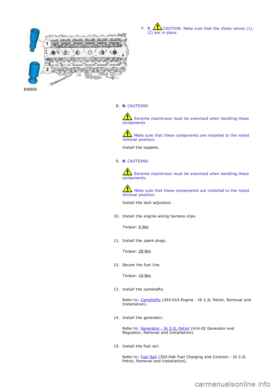
7. CAUTION: Make s ure that the choke valves (1),
(2) are i n place.
7.
8. CAUTIONS: Ext reme cl eanli ness must be exerci sed when handli ng t hes e
component s. Make s ure that t hes e component s are ins tal led t o t he noted
removal posi ti on.
Inst all t he tappets .
8.
9. CAUTIONS: Ext reme cl eanli ness must be exerci sed when handli ng t hes e
component s. Make s ure that t hes e component s are ins tal led t o t he noted
removal posi ti on.
Inst all t he las h adjus ters .
9.
Inst all t he engi ne wiring harnes s cli ps.
T orque: 6 Nm 10.
Inst all t he s park plugs .
T orque: 28 Nm 11.
Secure t he fuel li ne.
T orque: 10 Nm 12.
Inst all t he camshaft s .
Refer t o: Camshafts (303-01A Engine - I6 3.2L Pet rol , Removal and
Inst all at ion).
13.
Inst all t he generat or.
Refer t o: Generator - I6 3.2L Pet rol (414-02 Generator and
Regulator, Removal and Ins t allat ion).
14.
Inst all t he fuel rai l.
Refer t o: Fuel Rail (303-04A Fuel Chargi ng and Cont rol s - I6 3.2L
Petrol, Removal and Ins tall ati on).
15.