Page 548 of 3229
10 s econds .
W it h the engi ne at idle, s lowl y turn t he s teeri ng wheel and
hold on full l ock. Record t he pres s ure readi ng.
Repeat t he above procedure for t he other s ide. Record t he pres s ure readi ng.16.
W it h the engi ne at idle, rel ease the s t eering wheel. The press ure
s houl d be, at or bel ow, the pres s ure specified.
17.
Pres s ure out si de t hi s t olerance, i ndicat es a fault .
18.
19. CAUTION: Pump damage wi ll occur if t he t est valve is
clos ed for l onger peri ods .
To det ermi ne if t he fault is i n t he st eeri ng pump or the st eeri ng
rack, clos e the tes t val ve for a maxi mum of 5 s econds.
19.
If the press ures recorded fal l out s ide t he given values, replace the
power st eeri ng pump.
20.
If the maxi mum pump pres sure i s correct, t hen s uspect the power
s teering rack.
21.
22. CAUTION: Dis card flui d s iphoned from t he power st eeri ng
s yst em.
On compl et ion of t he t est s t op the engi ne, dis connect t he bat t ery
ground cable and s i phon t he fluid from t he power st eering res ervoir.
22.
Di sas s emble t he t es t equipment .
23.
Clean t he component mat ing faces . Inst all a new O-ring s eal.
Connect t he high-press ure li ne to the power s teeri ng pump.
T orque:
22 Nm 24.
Secure t he power s t eering hi gh pres s ure pi pe support bracket.
25.
Secure t he fuel li nes to the power s teeri ng high press ure pipe wi th
new cable t ies .
26.
Inst all t he turbocharger int ake tube.
27.
Inst all t he engi ne cover.
Refer t o: Engi ne Cover - TD4 2.2L Dies el (501-05 Interior Tri m and
Ornament ati on, Removal and Ins tal lat ion).
28.
Connect t he batt ery ground cable.
Refer t o: Specificati ons (414-00 Bat tery and Charging Sys tem -
General Informat ion, Specificati ons).
29.
30. CAUTION: Only us e new fl uid from a s ealed container.
Refi ll and bleed t he power st eeri ng.
30.
Page 565 of 3229
Publi s hed: 11-May-2011
Steering Linkage - Steering Linkage
Des cript ion and Operat ion
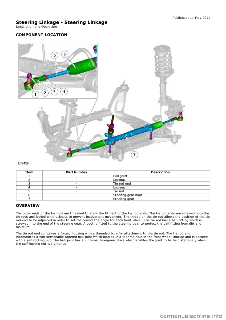
COMPONENT LOCATION
ItemPart NumberDescription
1-Ball joi nt2-Locknut
3-Tie rod end
4-Locknut5-Tie rod
6-Steeri ng gear boot
7-Steeri ng gear
OVERVIEW
The outer ends of the t ie rods are threaded t o al low t he fit ment of t he t ie rod ends. The t ie rod ends are s crewed onto t het ie rods and locked wit h locknut s t o prevent inadvertent movement. The t hread on t he t ie rod all ows the pos it ion of t he t ierod end to be adjust ed i n order t o s et the correct t oe angle for each front wheel. The t ie rod has a ball fit ti ng which i ss crewed int o t he end of the s t eering gear. A boot is fit ted t o t he s teering gear to protect t he bal l fi tt ing from dirt andmois t ure.
The t ie rod end compris es a forged hous ing wi th a t hreaded bore for at tachment to the t ie rod. The t ie rod endincorporat es a non-s ervi ceable t apered ball joint which l ocat es in a tapered hol e in the front wheel knuckl e and i s s ecuredwit h a sel f-locki ng nut. The ball joint has an int ernal hexagonal drive which enables t he joi nt to be hel d s t at ionary whent he sel f-locki ng nut is t ight ened.
Page 583 of 3229
The SRS el ect ri cal connectors are uni que. DO NOT force, orat tempt t o connect electrical connect ors t o t he wrong socket s .
Driver air bag module ins tall ati on can be confirmed by heari ng2 audibl e clicks , 1 for each s pring. The module edges s houl d als o beflus h wit h t he s teering wheel.
Inst all t he dri ver air bag modul e.
If ins tal led, connect t he SRS ride-down el ect ri cal connectorconcealed at t he rear of t he s teeri ng col umn.6.
Secure t he wiring harnes s t o t he s teeri ng column.7.
Connect t he s teeri ng col umn el ect ri cal connectors.8.
Inst all t he s teeri ng col umn upper cowl .9.
Inst all t he s teeri ng col umn l ower cowl.10.
Inst all t he dri ver l ower ai r bag modul e.
Refer t o: Dri ver Lower Air Bag Module (501-20B SupplementalRes traint Sys t em, Removal and Inst all at ion).
11.
Connect t he batt ery ground cable.
Refer t o: Specificati ons (414-00 Bat tery and Charging Sys tem -General Informat ion, Specificati ons).
12.
If a new s t eering column has been i nst all ed, confi gure t he s teeri ngcolumn l ock us i ng Land Rover approved di agnos t ic equipment.13.
Page 600 of 3229
Publ is hed: 02-Jun-2011
Engine System - General Information - Leakage Test Using Smoke Test
Equipment
General Procedures
CAUTION: The compres s ed air li ne s uppl y pres s ure mus t be bet ween 3.5 and 12 bar (50 and 175 psi ) for t he s moket es t equipment t o functi on correctl y. Do not exceed t hi s pres s ure. Fai lure t o fol low t his ins truct ion may res ult in damage tot he smoke tes t equi pment.
• NOTE: The vehi cle bat tery mus t be in good condit ion and ful ly charged before carryi ng out thi s procedure.
• NOTE: On vehicles wit h 3.0L TDV6, it wi ll be necess ary to ins ert s moke at bot h ai r cl eaner outl et pi pes independentl y ift he ri ght hand t urbocharger and as s oci at ed hos es are t o be t es ted.
• NOTE: In s ome cases i t may be necess ary to remove undert rays, t ri m or engine covers t o obt ai n acces s t o all potent ialleak l ocat ions.
• NOTE: Some vari ati on in the i ll us t rat ions may occur, but the es s ent ial informat ion i s always correct .
• NOTE: For furt her informati on regardi ng operati on of the tes t equi pment refer t o the manufacturers operat ors manuals uppl ied wi th the ki t.
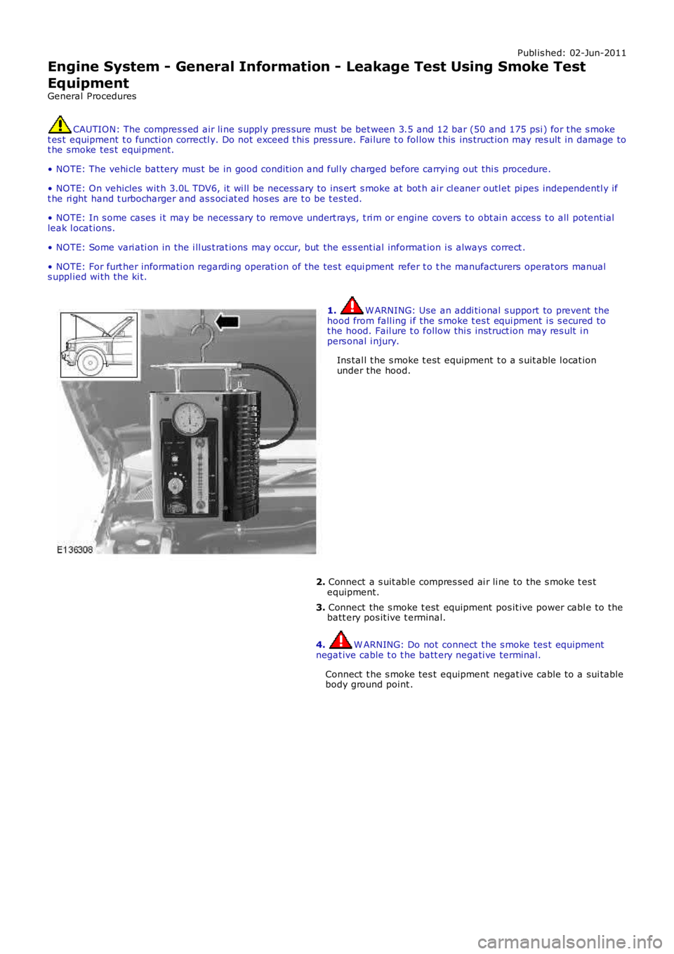
1. W ARNING: Use an addi ti onal s upport to prevent t hehood from fall ing i f the s moke t es t equi pment i s s ecured tot he hood. Fail ure t o follow thi s ins truct ion may res ult i npers onal i njury.
Ins tal l t he s moke t est equipment t o a s uit able l ocat ionunder the hood.
2. Connect a s uit abl e compres sed ai r li ne to the s moke t es tequipment.
3. Connect the s moke t est equipment pos it ive power cabl e to thebatt ery pos it ive t erminal.
4. W ARNING: Do not connect t he s moke tes t equipmentnegat ive cable t o t he batt ery negati ve terminal.
Connect t he s moke tes t equipment negat ive cable t o a sui tablebody ground point .
Page 609 of 3229
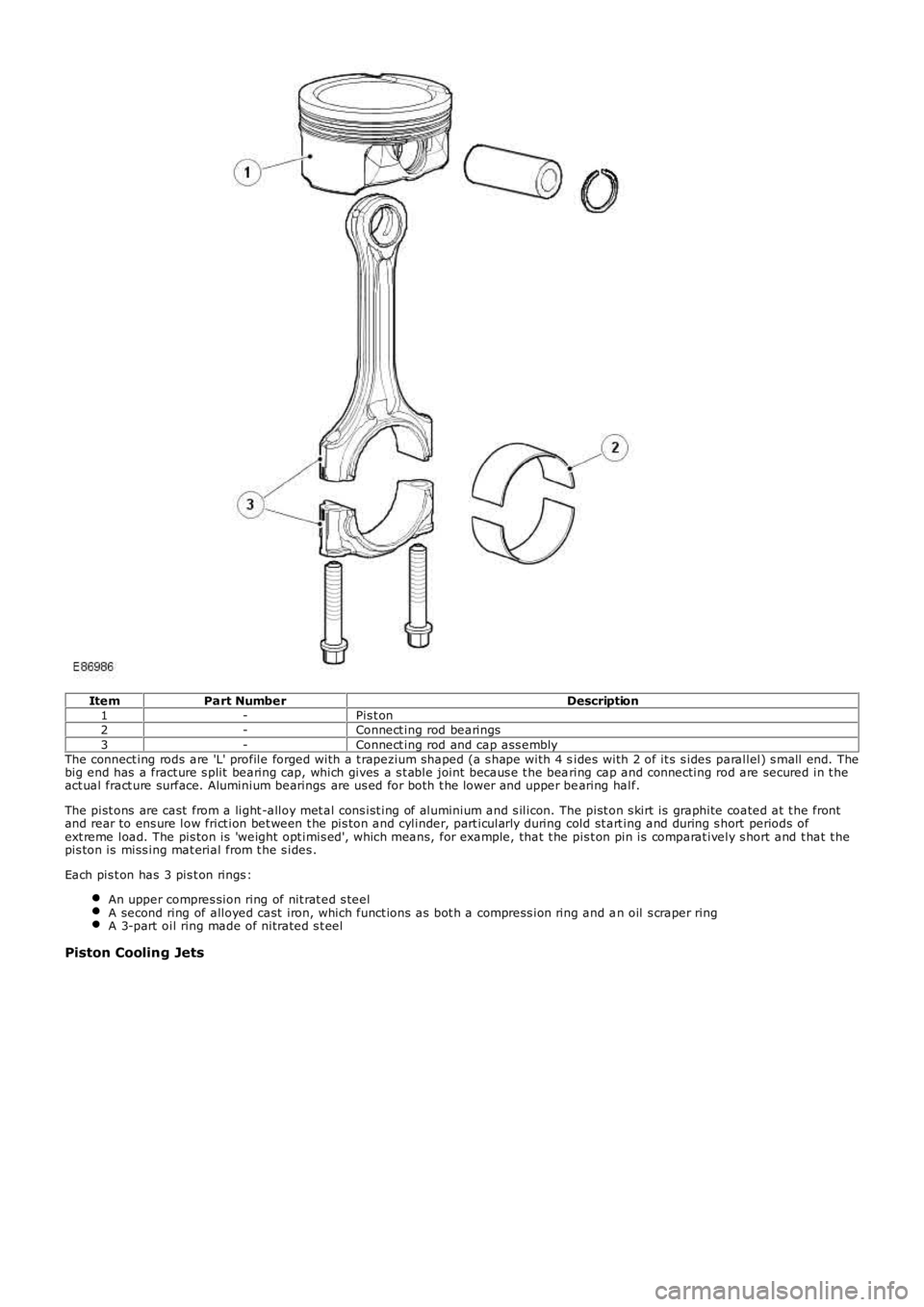
ItemPart NumberDescription1-Pis t on2-Connect ing rod bearings3-Connect ing rod and cap ass emblyThe connect ing rods are 'L' profile forged with a t rapezium shaped (a s hape with 4 sides with 2 of it s s ides parallel) s mall end. Thebig end has a fract ure s plit bearing cap, which gives a s t able joint becaus e t he bearing cap and connecting rod are secured in t heact ual fract ure surface. Aluminium bearings are us ed for both t he lower and upper bearing half.
The pist ons are cast from a light -alloy met al cons ist ing of aluminium and s ilicon. The pist on s kirt is graphite coated at t he frontand rear to ens ure low frict ion bet ween t he pis ton and cylinder, part icularly during cold st art ing and during s hort periods ofext reme load. The pis ton is 'weight opt imis ed', which means, for example, that t he pis t on pin is comparat ively s hort and t hat t hepis ton is miss ing mat erial from t he s ides .
Each pis t on has 3 pis t on rings :
An upper compres sion ring of nit rat ed s teelA second ring of alloyed cast iron, which funct ions as bot h a compress ion ring and an oil s craper ringA 3-part oil ring made of nitrated s t eel
Piston Cooling Jets
Page 616 of 3229
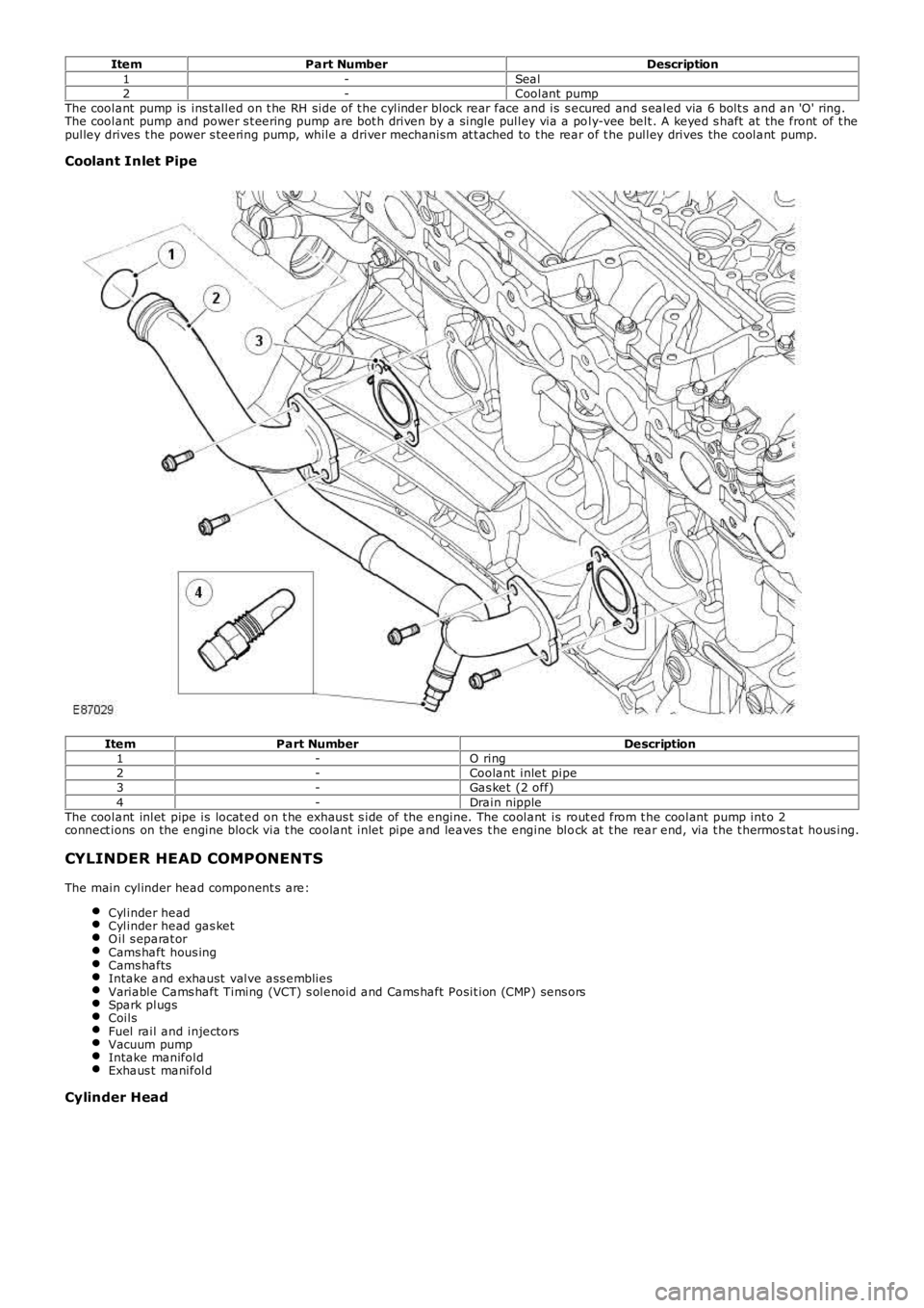
ItemPart NumberDescription1-Seal2-Coolant pumpThe coolant pump is ins t alled on t he RH side of t he cylinder block rear face and is s ecured and s ealed via 6 bolt s and an 'O' ring.The coolant pump and power s t eering pump are bot h driven by a single pulley via a poly-vee belt . A keyed s haft at the front of t hepulley drives t he power s teering pump, while a driver mechanism at t ached to t he rear of t he pulley drives the coolant pump.
Coolant Inlet Pipe
ItemPart NumberDescription1-O ring2-Coolant inlet pipe3-Gas ket (2 off)4-Drain nippleThe coolant inlet pipe is locat ed on t he exhaus t s ide of the engine. The coolant is rout ed from t he coolant pump int o 2connect ions on the engine block via t he coolant inlet pipe and leaves t he engine block at t he rear end, via t he t hermos tat hous ing.
CYLINDER HEAD COMPONENTS
The main cylinder head component s are:
Cylinder headCylinder head gas ketO il s eparat orCams haft hous ingCams haftsIntake and exhaust valve ass embliesVariable Cams haft Timing (VCT) s olenoid and Cams haft Posit ion (CMP) sens orsSpark plugsCoilsFuel rail and injectorsVacuum pumpIntake manifoldExhaus t manifold
Cylinder Head
Page 617 of 3229
The chill cas t cylinder head is of t he cros s-flow t ype, manufact ured from a light-alloy met al. Deep-s eat ed bolt s, to reducedis tortion, s ecure t he cylinder head t o t he cylinder block. Two hollow locat ing dowels align the cylinder head wit h t he cylinderblock. The 2 cams haft s are supported by 7 bearing caps each, direct ly in t he cylinder head and cams haft cover.
Cylinder Head Gasket
ItemPart NumberDescription1-Cylinder head gasketThe s eal bet ween the cylinder head and cylinder block is a conventional cylinder head gas ket . The head gasket is made of s t eeland has multiple layers . For s ervice, t here is only 1 s iz e of gas ket available.
Oil Separation Housing
Page 627 of 3229
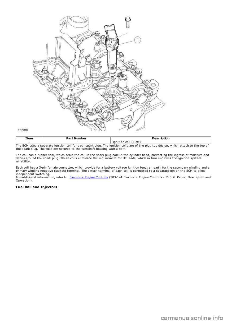
ItemPart NumberDescription1-Ignition coil (6 off)The ECM us es a s eparat e ignit ion coil for each spark plug. The ignit ion coils are of t he plug t op des ign, which at t ach t o t he t op ofthe s park plug. The coils are s ecured to the cams haft hous ing wit h a bolt.
The coil has a rubber seal, which s eals t he coil in the s park plug hole in t he cylinder head, prevent ing t he ingres s of mois t ure anddebris around t he spark plug. Thes e coils eliminat e t he requirement for HT leads , which in turn improves t he ignition s ys t emreliabilit y.
Each coil has a 3-pin female connect or, which provide for a bat tery volt age ignit ion feed, an eart h for t he s econdary winding and aprimary winding negat ive (s wit ch) terminal. The s wit ch t erminal of each coil is connect ed t o a separat e pin on t he ECM to allowindependent s wit ching.For addit ional information, refer t o: Elect ronic Engine Cont rols (303-14A Elect ronic Engine Controls - I6 3.2L Pet rol, Des cript ion andOperation).
Fuel Rail and Injectors