2006 LAND ROVER FRELANDER 2 ECU
[x] Cancel search: ECUPage 236 of 3229
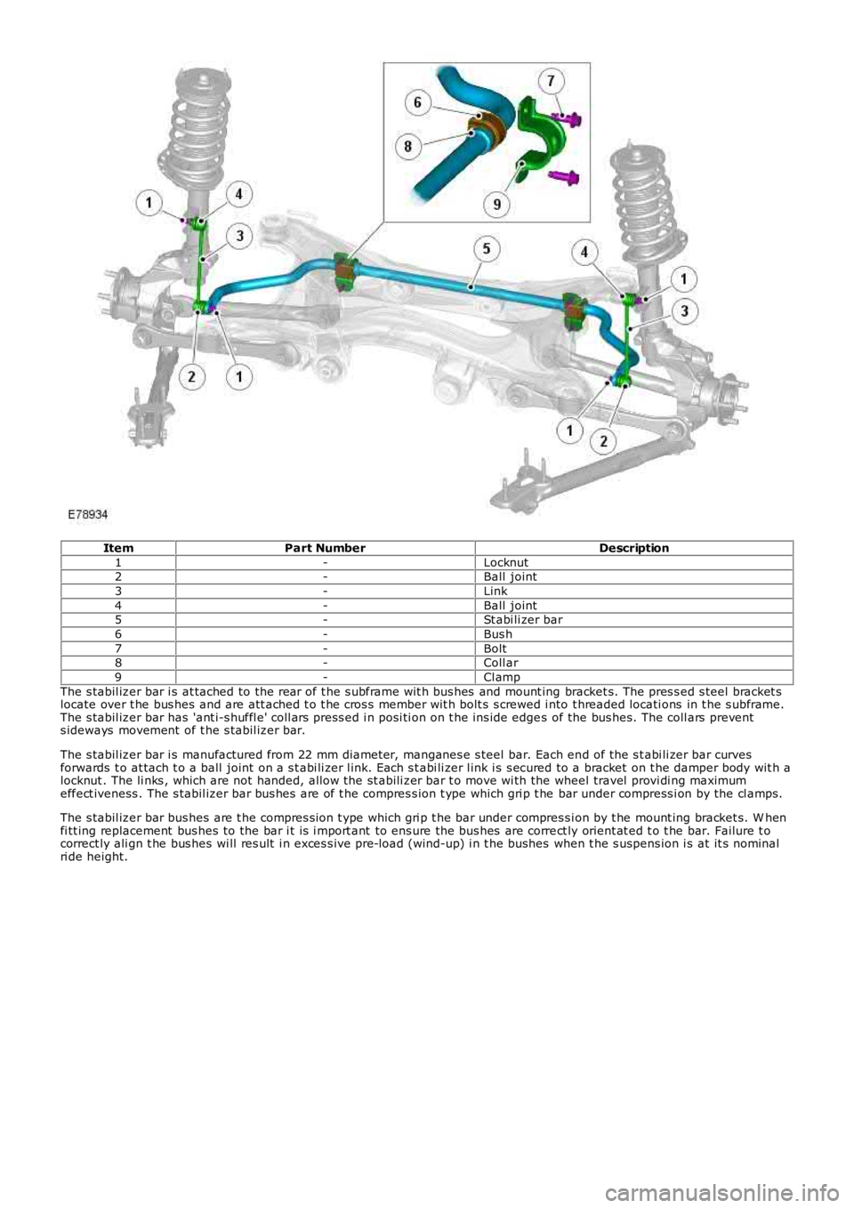
ItemPart NumberDescription
1-Locknut2-Ball joint
3-Link
4-Ball joint5-St abi li zer bar
6-Bus h
7-Bolt8-Coll ar
9-Cl amp
The s tabil izer bar i s at tached to the rear of t he s ubframe wit h bus hes and mount ing bracket s. The pres s ed s teel bracket slocate over t he bus hes and are att ached t o t he cros s member wit h bolt s s crewed i nto t hreaded locati ons in t he s ubframe.The s tabil izer bar has 'ant i-s huffl e' coll ars press ed i n posi ti on on t he ins ide edges of the bus hes. The coll ars prevents ideways movement of t he s tabil izer bar.
The s tabil izer bar i s manufactured from 22 mm diameter, manganes e s teel bar. Each end of the s t abi li zer bar curvesforwards t o at tach t o a ball joint on a s t abi li zer l ink. Each s t abi li zer l ink i s s ecured to a bracket on t he damper body wit h alocknut . The li nks , which are not handed, allow the st abili zer bar t o move wi th the wheel travel provi di ng maximumeffect iveness . The s tabil izer bar bus hes are of t he compres s ion t ype which gri p t he bar under compress i on by the cl amps.
The s tabil izer bar bus hes are t he compres s ion t ype which gri p t he bar under compres si on by t he mount ing bracket s. W henfi tt ing replacement bus hes to the bar i t is i mport ant to ens ure the bus hes are correct ly orient at ed t o t he bar. Failure t ocorrect ly ali gn t he bus hes wi ll res ult i n exces s ive pre-load (wind-up) i n t he bushes when t he s uspens ion i s at it s nominalri de height.
Page 246 of 3229
Publi s hed: 11-May-2011
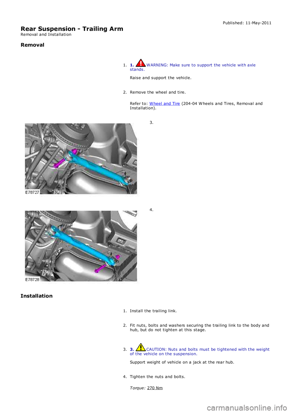
Rear Suspension - Trailing Arm
Removal and Inst all ati on
Removal
1. W ARNING: Make sure t o s upport the vehicle wit h axle
s tands .
Rais e and s upport t he vehi cl e.
1.
Remove t he wheel and t ire.
Refer t o: W heel and Ti re (204-04 W heel s and Tires, Removal and
Inst all at ion).
2. 3.
4.
Installation Inst all t he trail ing l ink.
1.
Fit nut s, bolt s and was hers s ecuring the t rai ling link to t he body and
hub, but do not t ight en at this st age.
2.
3. CAUTION: Nut s and bol ts mus t be ti ght ened wit h t he weight
of t he vehi cl e on t he s us pensi on.
Support weight of vehi cl e on a jack at the rear hub.
3.
Tight en the nut s and bolt s.
T orque: 270 Nm 4.
Page 262 of 3229
Inst all a new rear hal fs haft nut , do not full y t ighten at t his s t age.
16. CAUTION: Only ti ght en t he nut s and bolt s finger ti ght at
t his s t age.
Connect both lower arms to the hub as s embly, do not full y t ighten
at t hi s s tage.
16.
17. CAUTION: Only ti ght en t he nut and bol t fi nger-t ight at thi s
s tage.
Connect t he trail ing arm t o t he hub as sembl y, do not fully ti ght en at
t his s t age.
17.
18. CAUTION: Make s ure t hat the cl ip i s correct ly l ocat ed.
Connect t he parking brake cable. Secure t he parking brake cable.18.
19. CAUTION: Make s ure t hat the mati ng faces are cl ean and
free of foreign mat eri al.
Inst all t he brake dis c.
T orque: 35 Nm 19.
20. CAUTIONS: Make s ure that t he mat ing faces are clean and free of foreign
mat eri al . Make s ure that t he brake hos e is not t wis t ed and is correctl y
l ocated.
Secure t he brake caliper and anchor plat e t o t he wheel knuckl e.
T orque: 110 Nm 20.
Inst all t he rear wheel s peed s ens or t o t he wheel knuckle.
T orque: 5 Nm 21.
Inst all t he brake li ne and wheel speed s ensor brackets .
T orque: 10 Nm 22.
23. W ARNING: Make sure t hat a new nut is i nst all ed.
Secure t he s tabil izer bar l ink.
T orque: 60 Nm 23.
Support the weight of the vehicle us i ng a jack under the rear hub.
24.
25. CAUTIONS: Nut s and bolt s mus t be t ightened wi th the wei ght of t he
vehicle on the s us pens ion. Do not us e ai r tools to i nst all t he nut. Fail ure t o follow thi s
25.
Page 268 of 3229
10.
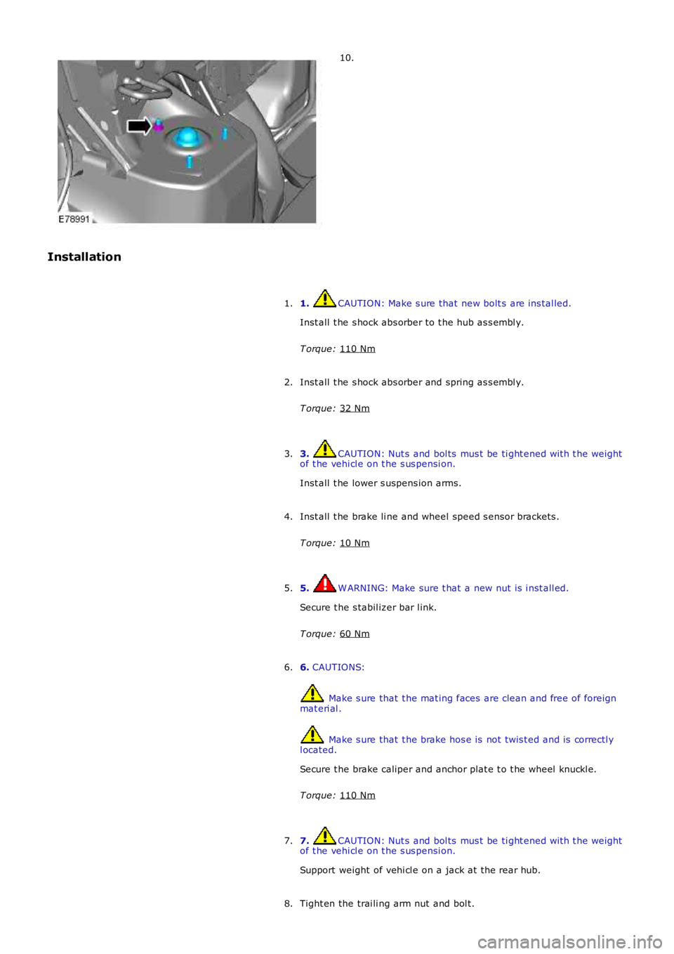
Installation 1. CAUTION: Make s ure that new bolt s are ins tal led.
Inst all t he s hock abs orber to t he hub as s embl y.
T orque: 110 Nm 1.
Inst all t he s hock abs orber and spring as s embl y.
T orque: 32 Nm 2.
3. CAUTION: Nut s and bol ts mus t be ti ght ened wit h t he weight
of t he vehi cl e on t he s us pensi on.
Inst all t he lower s uspens ion arms.
3.
Inst all t he brake li ne and wheel speed s ensor brackets .
T orque: 10 Nm 4.
5. W ARNING: Make sure t hat a new nut is i nst all ed.
Secure t he s tabil izer bar l ink.
T orque: 60 Nm 5.
6. CAUTIONS: Make s ure that t he mat ing faces are clean and free of foreign
mat eri al . Make s ure that t he brake hos e is not t wis t ed and is correctl y
l ocated.
Secure t he brake caliper and anchor plat e t o t he wheel knuckl e.
T orque: 110 Nm 6.
7. CAUTION: Nut s and bol ts mus t be ti ght ened wit h t he weight
of t he vehi cl e on t he s us pensi on.
Support weight of vehi cl e on a jack at the rear hub.
7.
Tight en the trai li ng arm nut and bol t.
8.
Page 277 of 3229
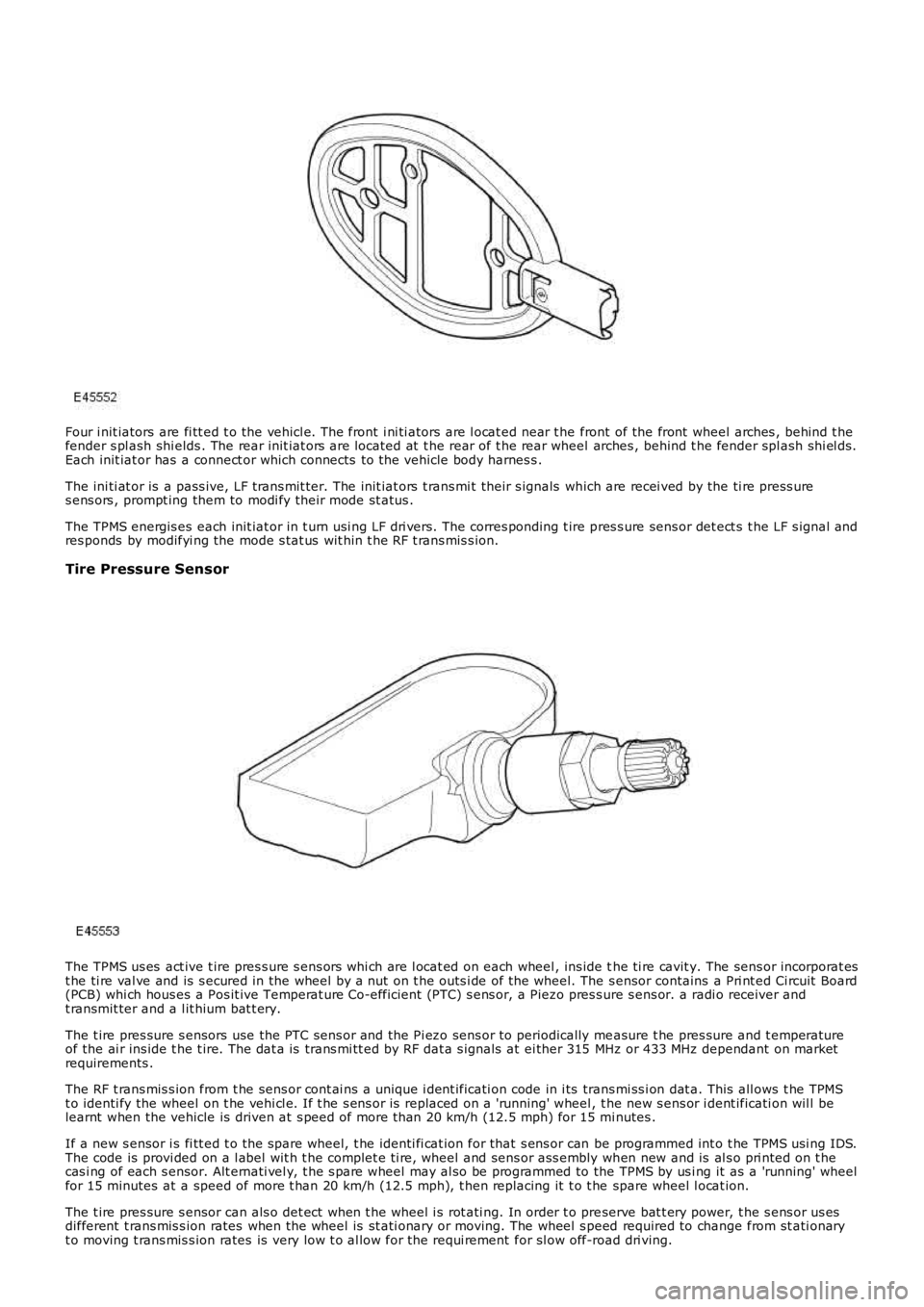
Four i nit iators are fi tt ed t o the vehicl e. The front i ni ti ators are l ocat ed near t he front of the front wheel arches , behind t hefender s pl ash shi elds . The rear init iat ors are located at t he rear of t he rear wheel arches , behind t he fender spl ash shi el ds.Each init iat or has a connect or which connects to the vehicle body harnes s .
The ini ti at or is a pass ive, LF t rans mit ter. The init iat ors t rans mi t their s ignals which are recei ved by the ti re press ures ens ors , prompt ing them to modi fy their mode st atus .
The TPMS energis es each init iat or in t urn usi ng LF dri vers. The corres ponding t ire pres s ure sens or det ect s t he LF s ignal andres ponds by modifyi ng the mode s tat us wit hin t he RF t rans mis s ion.
Tire Pressure Sensor
The TPMS us es act ive t ire pres s ure s ens ors whi ch are l ocat ed on each wheel , ins ide the ti re cavit y. The sens or incorporat est he ti re val ve and is s ecured in the wheel by a nut on t he outs i de of the wheel. The s ensor contains a Pri nt ed Ci rcuit Board(PCB) whi ch hous es a Pos it ive Temperat ure Co-efficient (PTC) s ens or, a Piezo pres s ure s ens or. a radi o receiver andt ransmit ter and a l it hium bat t ery.
The t ire pres sure s ensors use the PTC sens or and the Pi ezo sens or to periodically measure t he pres sure and t emperatureof the ai r ins ide t he t ire. The dat a is trans mi tt ed by RF dat a s ignals at ei ther 315 MHz or 433 MHz dependant on marketrequirements .
The RF t rans mis s ion from t he sens or cont ai ns a unique i dent ificati on code in i ts trans mi ss i on dat a. This all ows t he TPMSt o identi fy the wheel on t he vehi cl e. If t he s ens or is replaced on a 'running' wheel, t he new s ens or i dent ificati on wil l belearnt when the vehicle is driven at s peed of more t han 20 km/h (12.5 mph) for 15 minutes .
If a new s ensor i s fi tt ed t o t he spare wheel, t he identi fi cat ion for that s ens or can be programmed int o t he TPMS usi ng IDS.The code is provi ded on a l abel wit h t he complet e ti re, wheel and sens or ass embly when new and is al s o pri nted on t hecas i ng of each s ensor. Alt ernati vel y, t he s pare wheel may al so be programmed to the TPMS by us i ng it as a 'running' wheelfor 15 minutes at a speed of more t han 20 km/h (12.5 mph), t hen replacing it t o t he spare wheel l ocat ion.
The t ire pres sure s ensor can als o det ect when t he wheel i s rot ati ng. In order t o preserve bat t ery power, t he s ens or us esdifferent t rans mis s ion rates when the wheel is st ati onary or moving. The wheel s peed required to change from st ati onaryt o moving t rans mis s ion rates is very low t o al low for the requi rement for sl ow off-road dri ving.
Page 296 of 3229
programs.
Incorrect Program Usage
Selecti on of an inappropri at e program i s dis couraged in t he followi ng ways:
The act ive program icon is conti nual ly di spl ayed i n t he ins t rument clus ter mes s age centerThe Terrai n Res pons e control modul e 'l ocks ' out cert ain funct ions i n s ome programs, for exampl e:- cruis e control is only avai lable wi th the special programs off or gras s/gravel/s now program- t rans mis s ion 'Sport' mode i s deact ivated i n all s peci al programs .W hen t he i gni ti on has been in t he off mode, cont inuall y for more t han 6 hours , t he Terrai n Respons e s yst emdefault s t o t he special programs off.
Selecti on of an inappropri at e program for the t errain condit ions wil l not endanger the dri ver or cause damage to thevehi cl e. Cont inued us e of an inappropri ate program may reduce t he li fe of s ome component s . The driver may not icereduced vehi cl e res ponse, wi th the engine and t rans mi ss i on bei ng les s respons ive t han in s peci al programs off. Al so, i ns ome programs, HDC wil l remai n on, si gni fi ed by il lumi nat ion of t he HDC indicator in the i nst rument clus t er. The dri ver mayals o not ice t orque 'wi nd-up' i n t he act ive on-demand coupli ng caus ing a braking effect when the vehicl e is manoeuvred i ns ome s peci al programs .
Driver Information
The high-l ine i nst rument clus t er fit t ed to al l vehi cl es wit h Terrain Res pons e, cont ains a mess age center which di spl aysvehi cl e i nformat ion to t he driver. The mes s age cent er contai ns the Terrain Res ponse program icons which dis play t hecurrent ly s elected program. If no s ymbol i s dis played, no special program is sel ect ed and the sys tem is in 'Specialprograms off'.
Any required changes t o t he s ub-s ys t ems are al s o pass ed t o t he dri ver i n t he form of i ndi cat or ill uminat ion i n t heins t rument clus ter or appropriat e mes s ages i n t he mes s age center, 'HDC OFF' for example.
In certai n operati ng condi ti ons , t he Terrai n Res pons e s yst em al s o dis plays advi ce or warning mess ages to ens ure thedri ver i s us ing t he vehi cl e t o it s full potenti al, for example, s t eering angle is dis played i n t he mes sage center t o avoi ddri vi ng in deep rut s wit h s t eering l ock appli ed.
DIAGNOSTICS
The Terrai n Res pons e control modul e s tores informati on on detect ed Terrai n Respons e faul ts and CAN errors whi ch can beint errogat ed usi ng IDS. The Terrain Res ponse s ub-s ys t ems and t he ins trument cl ust er als o s tore informat ion relat ing t oCAN errors from t he Terrain Res pons e control modul e.
The cont rol module al s o s tores the mil es travel ed and ti me el aps ed for t he i ndi vi dual programs which can al so be ret ri evedus ing IDS. Thi s informat ion aids di agnos is of t he Terrain Res pons e s ys tem and als o provi des an indicati on of Terrai nRespons e s yst em abus e by t he dri ver whi ch can l ead to premat ure component failure.
This i nformat ion can al so be us ed to check cus t omer concerns , for exampl e, hi gh fuel cons umpt ion whi ch may be due t ocont inued us e of a cert ain program.
Terrain Response System Fault Diag nosis
Terrai n Res pons e relies on the correct funct ionali ty of t he 4 s ub-s ys tems . If one of the s ub-s ys tems develops a fault , theTerrai n Res pons e s ys tem wil l not funct ion, even though the fault i s NOT in t he Terrain Res pons e s ys tem.
T he T errain Response control module and rotary control should only be investigated if there are no apparent faultsin any of the sub-systems. If a fault in a sub-system is subsequently corrected, the T errain Response system willfunction normally after an ignition mode 1 and 2 (on and off) cycle.
Terrain Response Sub-System Faults
W hen a fault occurs i n a s ub-s yst em, t he dri ver i s alert ed by t he il lumi nat ion of a warning indicator and/or an appropri atemes s age for that s ub-s yst em in t he i ns t rument clus ter mes s age cent er. There wi ll be no warning of a Terrain Res ponses ys t em fault .
W hen a sub-sys t em faul t is present and t he dri ver at tempt s t o s el ect a different Terrain Res pons e program us i ng therot ary control or at t he next ignit ion mode 2 (on) cycl e, a mes sage 'SY STEM FAULT SPECIAL PROGRAMS NOT AVAILABLE'wil l appear in the mess age cent er. This impl ies t hat t he Terrain Res pons e s ys tem has a faul t, but only because asub-system fault is preventing its operation. Thi s mes sage will be di spl ayed for 5 s econds per ignit ion mode 2 cycl e, butis repeat ed i f a further s electi on is made by the driver usi ng t he Terrai n Respons e rot ary control or at t he next ignit ionmode 2 (on) cycle.
• NOTE: The mes s age 'SY STEM FAULT SPECIAL PRO GRAMS NOT AVAILABLE' can al so be generated by a fault i n t he Terrai nRespons e rot ary control or control modul e. Refer to the foll owing i nformat ion for det ail s of rot ary control or control modul efaul ts .
It is not possible for the T errain R esponse control module to cause any fault behavior (w arning indicator illuminationor message generation) in any of the 4 sub-systems. Illuminati on of a s ub-s ys t em warning i ndi cat or and/or as ub-s ys t em relat ed mes sage wi ll NEVER be ass ociated wit h a Terrain Res ponse cont rol module or Terrain Res pons es ys t em fault .
The s ub-s ys t em control modul es can det ect a fault wit h the CAN s ignal from t he Terrai n Res pons e control modul e. If afaul t in t he Terrain Res pons e s ys tem is det ect ed, the s ub-s ys tem cont rol modules wi ll operate in t he 'Special programs off's ett ing. The s ub-s ys t em control modul es wil l record a fault code for a fail ure of t he Terrai n Res pons e CAN si gnal . Thes efaul ts can be retrieved us ing IDS and wi ll provide us eful informat ion t o i ndi cat e i nves ti gat ion of t he Terrain Res pons econt rol module or t he CAN net work.
Terrain Response Rotary Control or Control Module Fault
Page 341 of 3229
15.
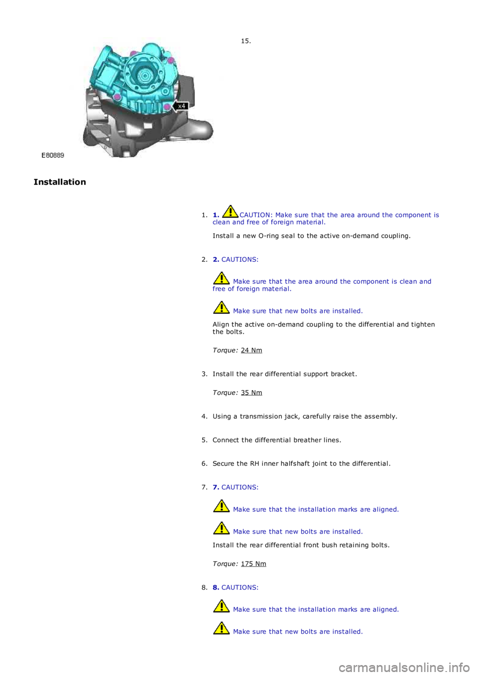
Installation 1. CAUTION: Make s ure that the area around t he component is
clean and free of foreign materi al.
Inst all a new O-ring s eal to the acti ve on-demand coupl ing.
1.
2. CAUTIONS: Make s ure that t he area around the component i s clean and
free of foreign mat eri al. Make s ure that new bolt s are ins t al led.
Ali gn t he act ive on-demand coupli ng to the di fferenti al and t ight en
t he bolt s.
T orque: 24 Nm 2.
Inst all t he rear different ial s upport bracket .
T orque: 35 Nm 3.
Us ing a transmis si on jack, carefull y rai s e the as s embly.
4.
Connect t he different ial breather l ines.
5.
Secure t he RH i nner halfs haft joi nt t o t he different ial .
6.
7. CAUTIONS: Make s ure that t he ins tal lat ion marks are al igned.
Make s ure that new bolt s are ins t al led.
Inst all t he rear different ial front bus h retai ni ng bolt s.
T orque: 175 Nm 7.
8. CAUTIONS: Make s ure that t he ins tal lat ion marks are al igned.
Make s ure that new bolt s are ins t al led.
8.
Page 355 of 3229
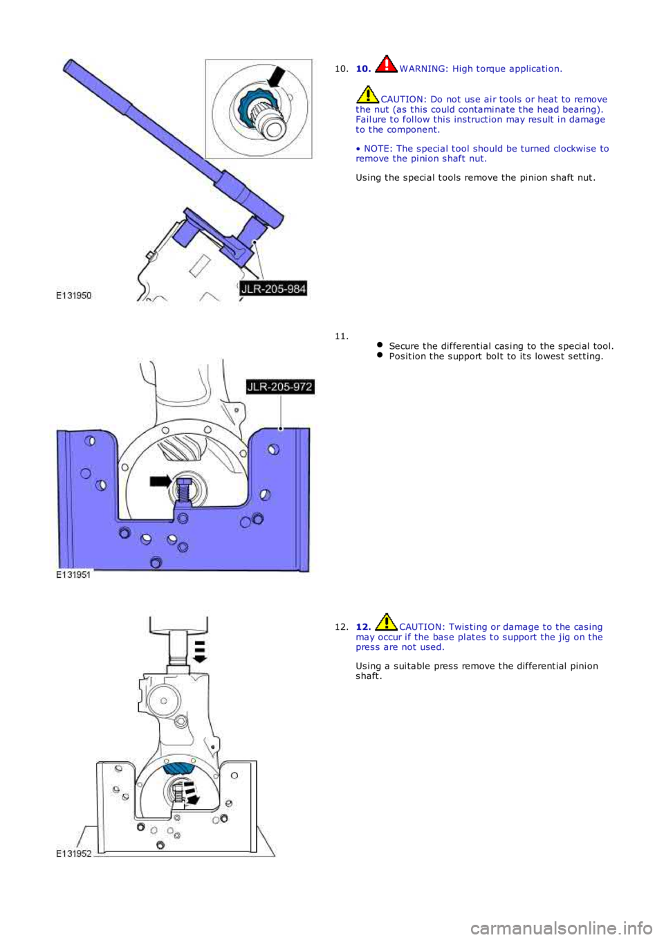
10. W ARNING: High t orque applicati on.
CAUTION: Do not us e ai r tools or heat to removet he nut (as t his could contami nate t he head bearing).Fail ure t o fol low thi s ins truct ion may res ult i n damaget o t he component.
• NOTE: The s peci al t ool should be turned cl ockwi se toremove the pi ni on s haft nut.
Us ing t he s peci al t ools remove the pi nion s haft nut .
10.
Secure t he different ial cas i ng to the s peci al tool.Pos it ion t he s upport bol t to it s lowes t s et t ing.
11.
12. CAUTION: Twis t ing or damage t o t he cas ingmay occur i f the bas e pl at es t o s upport the jig on thepres s are not used.
Us ing a s ui table pres s remove t he different ial pini ons haft .
12.