Page 357 of 3229

16. CAUTION: It is es s ent ial t hat abs olut e cleanl ines s isobs erved when working on the rear different ial. Al ways cover anyopen ori fi ces us ing lint free non-flocking mat eri al t o prevent t hei ngress of foreign matt er. Fail ure t o follow thi s ins truct ion mayres ult damage t o t he component s.
Remove t he different ial from t he s upporti ng tool .Thoroughl y clean t he pinion shaft paying parti cul ar at t ent iont o t he thread.Us ing a s ui table cl eani ng fl uid t horoughly clean t hedifferent ial casi ngs .
16.
Installation
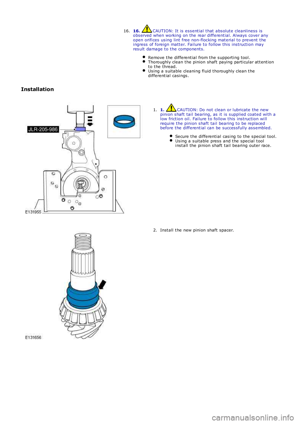
1. CAUTION: Do not clean or l ubricate the newpini on s haft tai l bearing, as it i s s uppl ied coat ed wi th al ow frict ion oil . Fai lure t o fol low t his ins truct ion wi llrequi re t he pini on s haft tai l bearing t o be repl acedbefore t he different ial can be succes s ful ly as s embled.
Secure t he different ial cas i ng to the s peci al tool.Us ing a s ui table pres s and t he special t ooli ns t all the pi nion s haft t ail bearing out er race.
1.
Inst all t he new pini on shaft spacer.2.
Page 372 of 3229
Publi s hed: 13-May-2011
Front Drive Halfshafts - Front Halfshaft LH
Removal and Inst all ati on
Special T ool(s)
204-619G-Clamp
205-754ASpli tt er, Ball Joint s
205-857Remover, Halfs haft
Removal
• NOTE: The s eal protector is not a s pecial t ool but is avail able from the parts catalogue.
Remove t he plenum chamber panel.
Refer t o: Plenum Chamber (412-01 Cl imat e Control, Removal andInst all at ion).
1.
Releas e t he hood support s t rut s and s ecure the hood i nan upri ght pos it ion.2.
3. W ARNING: Make sure t o s upport the vehicle wit h axles tands .
Rais e and s upport t he vehi cl e.
3.
Remove t he wheel and t ire.
Refer t o: W heel and Ti re (204-04 W heel s and Tires, Removal andInst all at ion).
4.
Page 376 of 3229
Publi s hed: 18-May-2011
Front Drive Halfshafts - Front Halfshaft RH
Removal and Inst all ati on
Special T ool(s) 204-619
G-Clamp 205-754A
Spli tt er, Ball Joint s 205-857
Remover, Halfs haft
Removal Remove t he plenum chamber panel.
Refer t o: Plenum Chamber (412-01 Cl imat e Control, Removal and
Inst all at ion).
1. Releas e t he hood support s t rut s and s ecure the hood i n
an upri ght pos it ion.
2.
3. W ARNING: Make sure t o s upport the vehicle wit h axle
s tands .
Rais e and s upport t he vehi cl e.
3.
Remove t he wheel and t ire.
Refer t o: W heel and Ti re (204-04 W heel s and Tires, Removal and
Inst all at ion).
4.
Page 382 of 3229
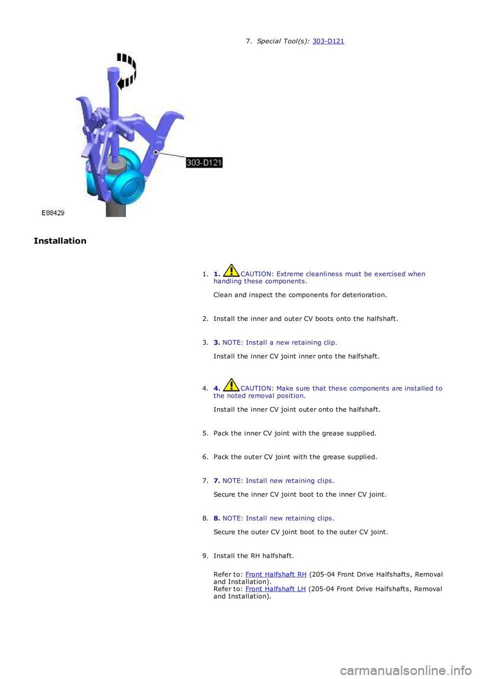
Speci al Tool (s ):
303-D121 5.
Installation 1. CAUTION: Extreme cleanli nes s mus t be exercis ed when
handl ing t hese components .
Clean and i nspect the components for det eri orati on.
1.
Inst all t he inner CV boot ont o t he halfshaft .
2.
3. NOTE: Ins t al l a new retaini ng clip.
Inst all t he inner CV joi nt inner ont o t he halfshaft .
3.
4. CAUTION: Make s ure that thes e component s are ins tall ed t o
t he noted removal pos it ion.
Inst all t he inner CV joi nt out er ont o t he halfshaft.
4.
Pack the i nner CV joint wi th the grease suppli ed.
5.
6. NOTE: Ins t al l new ret aining cl ips .
Secure t he inner CV joi nt boot t o t he inner CV joint.
6.
Inst all t he hal fs haft .
Refer t o: Front Halfs haft RH (205-04 Front Dri ve Halfs haft s , Removal
and Inst all at ion).
Refer t o: Front Halfs haft LH (205-04 Front Drive Hal fs haft s , Removal
and Inst all at ion).
7.
Page 385 of 3229

Speci al Tool (s ):
303-D121 7.
Installation 1. CAUTION: Extreme cleanli nes s mus t be exercis ed when
handl ing t hese components .
Clean and i nspect the components for det eri orati on.
1.
Inst all t he inner and out er CV boots ont o t he hal fs haft .
2.
3. NOTE: Ins t al l a new retaini ng clip.
Inst all t he inner CV joi nt inner ont o t he halfshaft .
3.
4. CAUTION: Make s ure that thes e component s are ins tall ed t o
t he noted removal pos it ion.
Inst all t he inner CV joi nt out er ont o t he halfshaft.
4.
Pack the i nner CV joint wi th the grease suppli ed.
5.
Pack the out er CV joi nt wit h t he grease s uppli ed.
6.
7. NOTE: Ins t al l new ret aining cl ips .
Secure t he inner CV joi nt boot t o t he inner CV joint.
7.
8. NOTE: Ins t al l new ret aining cl ips .
Secure t he outer CV joint boot to t he outer CV joint .
8.
Inst all t he RH halfs haft.
Refer t o: Front Halfs haft RH (205-04 Front Dri ve Halfs haft s , Removal
and Inst all at ion).
Refer t o: Front Halfs haft LH (205-04 Front Drive Hal fs haft s , Removal
and Inst all at ion).
9.
Page 394 of 3229

Stage 1:
Stage 2:
Secure t he parking brake cable.
8.
Support the weight of the vehicle us i ng a jack under the rear hub.
9.
10. CAUTIONS: Nut s and bolt s mus t be t ightened wi th the wei ght of t he
vehicle on the s us pens ion. Do not us e ai r tools to i nst all t he nut. Fail ure t o follow thi s
i ns t ructi on may resul t in damage t o t he component.
Tight en bot h l ower arm nut s and bolt s .
T orque: 175 Nm Tight en the trai li ng arm nut and bol t.
T orque: 270 Nm Tight en the rear hal fs haft nut .
T orque: 330 Nm 30°
St ake t he hub nut.10.
Inst all t he s tabil izer bar l ink.
Refer t o: Rear St abi li zer Bar Link (204-02 Rear Sus pensi on, Removal
and Inst all at ion).
11.
Inst all t he wheel and t ire.
Refer t o: W heel and Ti re (204-04 W heel s and Tires, Removal and
Inst all at ion).
12.
13. CAUTION: Do not fill t he different ial wi th lubri cant up t o
t he fi ll er pl ug. The fil ler plug i s only us ed t o fill t he different ial wi th
l ubricant , and not to act as a level i ndicat or.
Fil l the di fferenti al wi th the correct amount of l ubricant .
Refer t o: Different ial Drai ni ng and Fil ling (205-02 Rear Drive
Axle/Different ial, General Procedures).
13.
Page 399 of 3229

Stage 1:
Stage 2:
Secure t he parking brake cable.
8.
Support the weight of the vehicle us i ng a jack under the rear hub.
9.
10. CAUTIONS: Nut s and bolt s mus t be t ightened wi th the wei ght of t he
vehicle on the s us pens ion. Do not us e ai r tools to i nst all t he nut. Fail ure t o follow thi s
i ns t ructi on may resul t in damage t o t he component.
Tight en bot h l ower arm nut s and bolt s .
T orque: 175 Nm Tight en the trai li ng arm nut and bol t.
T orque: 270 Nm Tight en the rear hal fs haft nut .
T orque: 330 Nm 30°
St ake t he hub nut.10.
Inst all t he s tabil izer bar l ink.
Refer t o: Rear St abi li zer Bar Link (204-02 Rear Sus pensi on, Removal
and Inst all at ion).
11.
Inst all t he wheel and t ire.
Refer t o: W heel and Ti re (204-04 W heel s and Tires, Removal and
Inst all at ion).
12.
13. CAUTION: Do not fill t he different ial wi th lubri cant up t o
t he fi ll er pl ug. The fil ler plug i s only us ed t o fill t he different ial wi th
l ubricant , and not to act as a level i ndicat or.
Fil l the di fferenti al wi th the correct amount of l ubricant .
13.
Page 401 of 3229
5.
NOTE: Dis card t he ret aining cl ip.
5. Speci al Tool (s ):
303-D121 6.
Installation 1. CAUTION: Extreme cleanli nes s mus t be exercis ed when
handl ing t hese components .
Clean and i nspect the components for det eri orati on.
1.
Inst all t he inner CV boot ont o t he halfshaft .
2.
3. NOTE: Ins t al l a new retaini ng clip.
Inst all t he inner CV joi nt inner ont o t he halfshaft .
3.
4. CAUTION: Make s ure that thes e component s are ins tall ed t o
t he noted removal pos it ion.
Inst all t he inner CV joi nt out er ont o t he halfshaft.
4.
Pack the i nner CV joint wi th the grease suppli ed.
5.
6. NOTE: Ins t al l new ret aining cl ips .
Secure t he inner CV joi nt boot t o t he inner CV joint.
6.
Inst all t he hal fs haft .
7.