Page 690 of 3229
Apply a bead of s ealant, 2.5 mm diamet er, t o t he area
i ndi cat ed.
3.
Inst all t he oil pan.
T orque: M7 17 Nm M10
45 Nm 4.
Secure t he cool ant rail .
T orque: 10 Nm 5.
Inst all t he int ake mani fol d.
T orque: 10 Nm 6.
7. CAUTION: Make s ure that new s ealing was hers are i nst all ed.
Inst all t he lubri cant drai n plug.
T orque: 38 Nm 7.
Fil l the engine wit h oil .
8.
Inst all t he s tart er mot or.
Refer t o: Start er Motor (303-06A Starti ng Sys t em - I6 3.2L Pet rol ,
Removal and Ins tall ati on).
9.
Check and top-up the engine oi l.
10.
Connect t he batt ery ground cable and ins tall t he cover.
Refer t o: Specificati ons (414-00 Bat tery and Charging Sys tem -
General Informat ion, Specificati ons).
11.
Inst all t he dips ti ck tube.
T orque: 10 Nm 12.
Page 697 of 3229
Publi s hed: 11-May-2011
Engine - I6 3.2L Petrol - Oil Filter Element
Removal and Inst all ati on
Removal
Releas e t he PAS fl uid reservoi r from t he bracket and ti e as ide.
1. Loosen t he element cover 4 compl ete t urns t o al low
engine oil t o drai n from the fil ter cover.
2. 3.
Installation Inst all t he oil fi lt er element.
1.
Inst all t he engi ne oil filt er.
T orque: 25 Nm 2.
Secure t he res ervoir.
3.
Check and top-up the engine oi l.
4.
Page 716 of 3229
T orque:
17 Nm Inst all t he power s t eering pump.
T orque: 25 Nm 12.
Connect and s ecure t he HO2S electrical connect ors .
13.
Inst all t he power s t eering pump support bracket.
T orque: 25 Nm 14.
Inst all t he ti ming chain and sprockets .
Refer t o: Timi ng Chai n (303-01A Engi ne - I6 3.2L Pet rol, Removal
and Inst all at ion).
15.
Connect t he batt ery ground cable and ins tall t he cover.
Refer t o: Specificati ons (414-00 Bat tery and Charging Sys tem -
General Informat ion, Specificati ons).
16.
Page 735 of 3229
5. CAUTION: Inspect the l ocki ng pin for damage.
If the l ocki ng pin i s broken in the engine bl ock, t he
engine block mus t be repl aced. Failure t o fol low this
i ns t ructi on may resul t in damage t o t he vehi cl e.
5.
Installation Apply a 2.5mm bead of sealant STC50550 (Loct it e
5900) to t he areas s hown.
1. 2. CAUTION: Make s ure that the mati ng faces are
clean and free of foreign materi al.
Inst all t he s eal ing was her to t he READ i dler
s haft as sembl y.
1.
Us ing a s ui table tool, deform the s eali ng was her
t o s ecure it t o t he READ i dler ass embly.
2.
2. 3. CAUTION: Make s ure that the mati ng faces are
clean and free of foreign materi al.
Speci al Tool (s ): 303-1486 3.
Refer t o: Rear End Acces s ory Drive (READ) (303-05A Access ory Dri ve
4.
Page 749 of 3229

Stage 1:
Stage 2:
T orque:
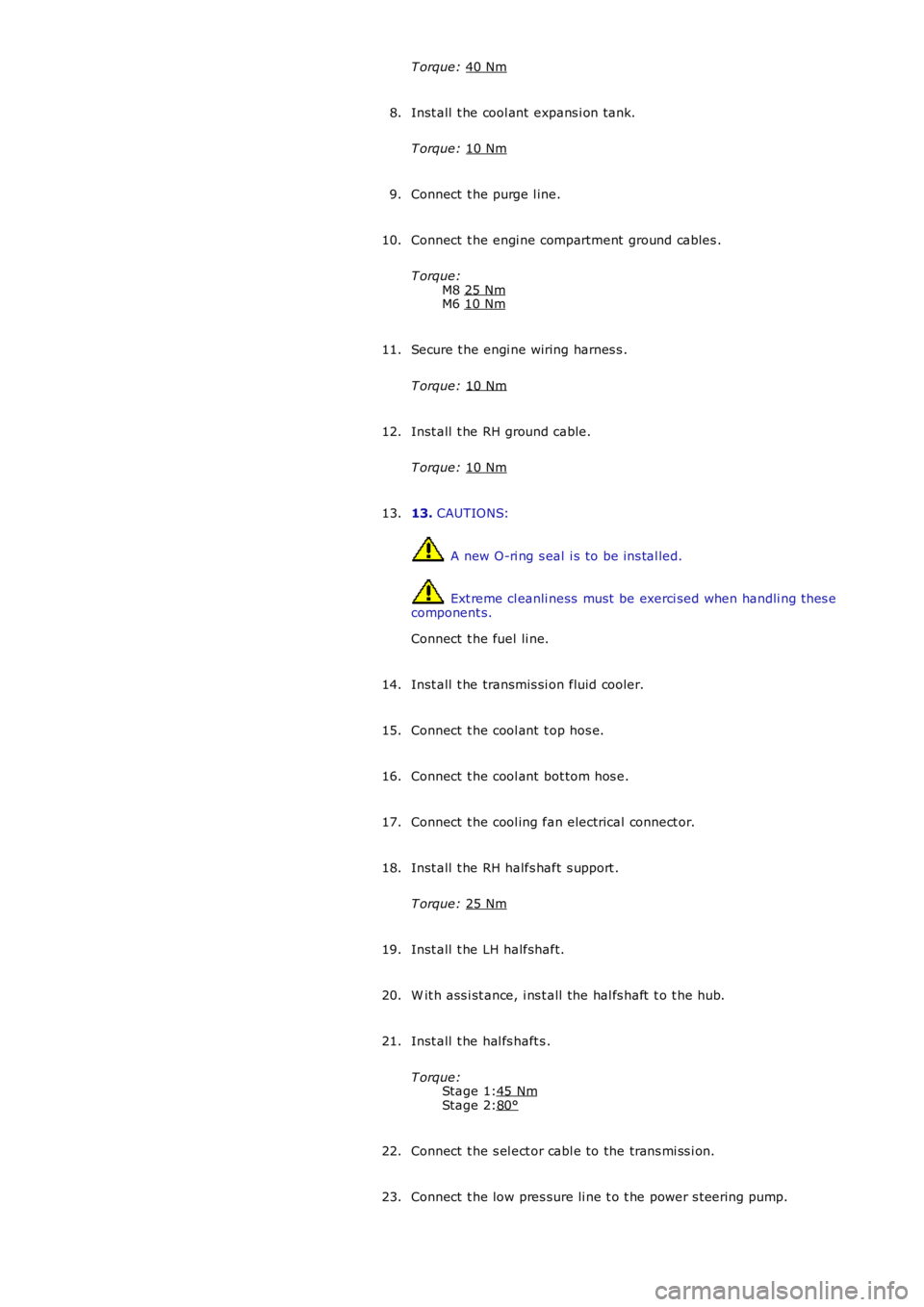
40 Nm Inst all t he cool ant expans i on tank.
T orque: 10 Nm 8.
Connect t he purge l ine.
9.
Connect t he engi ne compartment ground cables .
T orque: M8 25 Nm M6
10 Nm 10.
Secure t he engi ne wiring harnes s .
T orque: 10 Nm 11.
Inst all t he RH ground cable.
T orque: 10 Nm 12.
13. CAUTIONS: A new O-ri ng s eal i s to be ins tal led.
Ext reme cl eanli ness must be exerci sed when handli ng t hes e
component s.
Connect t he fuel li ne.
13.
Inst all t he transmis si on fluid cooler.
14.
Connect t he cool ant t op hos e.
15.
Connect t he cool ant bot tom hos e.
16.
Connect t he cool ing fan electrical connect or.
17.
Inst all t he RH halfs haft s upport .
T orque: 25 Nm 18.
Inst all t he LH halfshaft.
19.
W it h ass i st ance, i ns t all the hal fs haft t o t he hub.
20.
Inst all t he hal fs haft s .
T orque: 45 Nm 80°21.
Connect t he s el ect or cabl e to the trans mi ss i on.
22.
Connect t he low pres sure li ne t o t he power s t eering pump.
23.
Page 750 of 3229

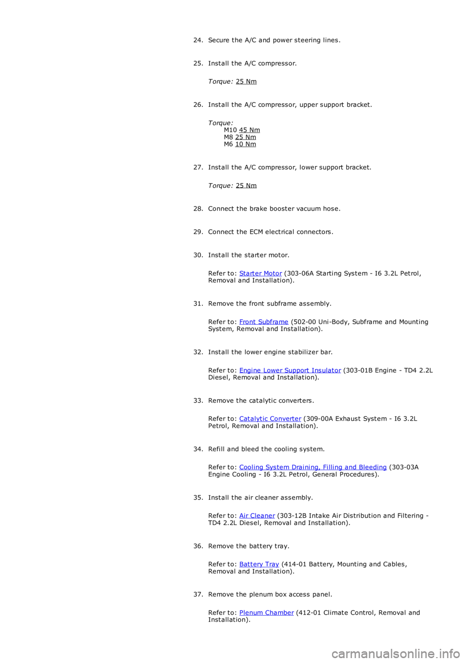
Secure t he A/C and power s t eering l ines .
24.
Inst all t he A/C compress or.
T orque: 25 Nm 25.
Inst all t he A/C compress or, upper s upport bracket.
T orque: M10 45 Nm M8
25 Nm M6
10 Nm 26.
Inst all t he A/C compress or, l ower support bracket.
T orque: 25 Nm 27.
Connect t he brake boost er vacuum hos e.
28.
Connect t he ECM elect rical connectors .
29.
Inst all t he s tart er mot or.
Refer t o: Start er Motor (303-06A Starti ng Sys t em - I6 3.2L Pet rol ,
Removal and Ins tall ati on).
30.
Remove t he front subframe as s embly.
Refer t o: Front Subframe (502-00 Uni -Body, Subframe and Mount ing
Syst em, Removal and Ins tall ati on).
31.
Inst all t he lower engi ne s tabil izer bar.
Refer t o: Engi ne Lower Support Ins ulat or (303-01B Engine - TD4 2.2L
Di es el, Removal and Ins tal lat ion).
32.
Remove t he cat alyti c convert ers .
Refer t o: Cat alyt ic Converter (309-00A Exhaus t Syst em - I6 3.2L
Petrol, Removal and Ins tall ati on).
33.
Refi ll and bleed t he cool ing s ys tem.
Refer t o: Cool ing Sys tem Drai ni ng, Fi lli ng and Bleeding (303-03A
Engine Cooli ng - I6 3.2L Petrol, General Procedures).
34.
Inst all t he air cleaner as s embly.
Refer t o: Air Cleaner (303-12B Intake Ai r Dis tribut ion and Fil tering -
TD4 2.2L Dies el, Removal and Inst all ati on).
35.
Remove t he bat t ery t ray.
Refer t o: Bat t ery Tray (414-01 Bat tery, Mount ing and Cables ,
Removal and Ins tall ati on).
36.
Remove t he plenum box acces s panel.
Refer t o: Plenum Chamber (412-01 Cl imat e Control, Removal and
Inst all at ion).
37.
Page 755 of 3229

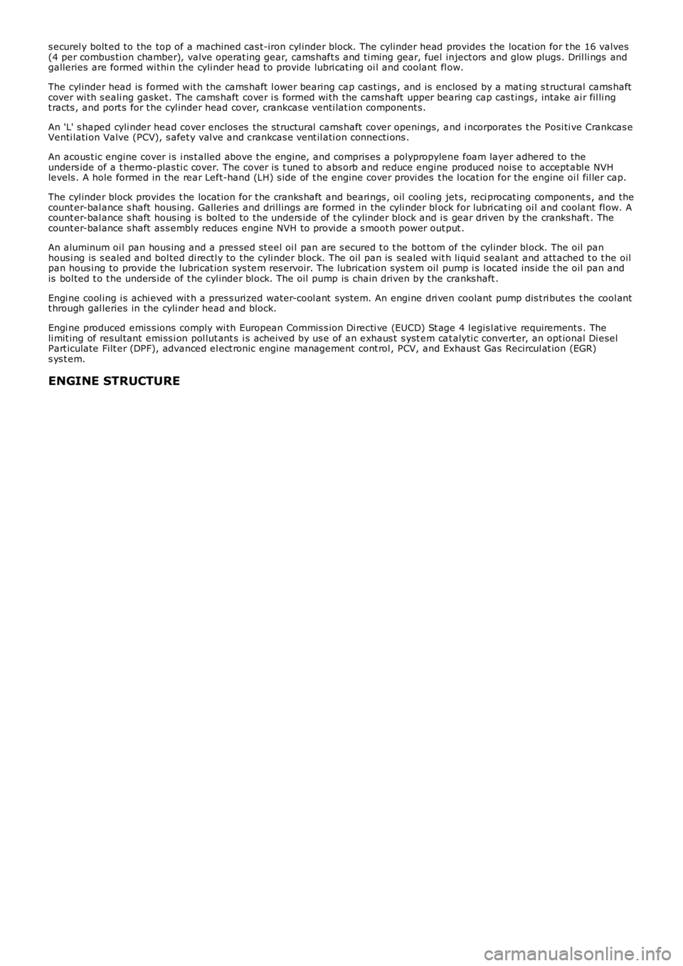
s ecurel y bolt ed to the top of a machined cas t-iron cyl inder block. The cylinder head provides t he locati on for t he 16 valves(4 per combus ti on chamber), valve operat ing gear, cams haft s and ti ming gear, fuel inject ors and glow plugs. Dril li ngs andgalleries are formed wi thi n the cyli nder head t o provide lubri cat ing oi l and coolant fl ow.
The cyl inder head is formed wit h the cams haft l ower bearing cap cas t ings , and is enclos ed by a mat ing s t ructural cams haftcover wi th s eali ng gasket. The cams haft cover i s formed wi th the cams haft upper beari ng cap cas t ings , intake ai r fil li ngt racts , and port s for t he cyl inder head cover, crankcas e venti lat ion component s.
An 'L' s haped cyli nder head cover enclos es the s t ructural cams haft cover openings, and i ncorporates t he Posi ti ve Crankcas eVenti lati on Valve (PCV), s afet y val ve and crankcas e vent il ati on connecti ons .
An acous t ic engine cover i s i ns t alled above t he engi ne, and compris es a polypropylene foam layer adhered to theunders ide of a t hermo-plas ti c cover. The cover i s t uned t o abs orb and reduce engine produced nois e t o accept abl e NVHlevels . A hole formed in the rear Left-hand (LH) s ide of t he engine cover provi des the l ocat ion for the engine oi l fil ler cap.
The cyl inder block provides t he locat ion for t he cranks haft and beari ngs , oil cooling jet s, reci procat ing component s , and thecount er-bal ance s haft hous ing. Galleries and drill ings are formed in the cyli nder block for lubri cat ing oi l and coolant fl ow. Acount er-bal ance s haft hous ing i s bolt ed to the unders ide of t he cylinder block and is gear dri ven by the cranks haft . Thecount er-bal ance s haft as s embly reduces engine NVH to provi de a s moot h power out put .
An aluminum oi l pan hous ing and a pres sed st eel oi l pan are s ecured t o t he bot t om of t he cyl inder bl ock. The oil panhous i ng is s ealed and bol ted di rectl y to the cyli nder block. The oil pan is sealed wit h li qui d s ealant and att ached t o t he oilpan hous i ng to provide t he lubricat ion sys tem res ervoir. The lubricat ion sys tem oil pump i s l ocated ins ide t he oil pan andis bol ted t o t he unders ide of t he cyl inder bl ock. The oil pump is chain driven by t he cranks haft .
Engi ne cool ing i s achi eved wit h a pres s uri zed water-cool ant sys tem. An engi ne dri ven coolant pump dis t ri but es t he cool antt hrough gal leries in the cyli nder head and block.
Engi ne produced emis s ions comply wi th European Commis s ion Di recti ve (EUCD) St age 4 legis l at ive requirement s . Theli mit ing of res ul tant emi ss i on pol lut ant s i s acheived by us e of an exhaus t s yst em cat alyti c convert er, an opt ional Di eselPart iculate Filt er (DPF), advanced el ect ronic engine management cont rol , PCV, and Exhaus t Gas Recircul at ion (EGR)s ys t em.
ENGINE STRUCTURE
Page 764 of 3229
ItemPart NumberDescription
1-CKP s ens or2-CKP s ens or target ring
A CKP sens or is i ns t alled at the front of the engi ne, and i s s ecured to the cyli nder block wi th a locati ng dowel and s crew.The posi ti on of the sens or is not adjus table. The s ensor head is pos i ti oned clos e t o a corres ponding target ring l ocat edbehi nd t he cranks haft drive pull ey. The t arget ri ng is keyed on t o t he crankshaft.
The s ens or is a variabl e rel uct ance s ens or t hat provides an i nput of engi ne crankshaft speed, and No. 1 pis ton pos it ion tot he ECM. The informati on is us ed by t he ECM t o det ermi ne the quanti ty of fuel to be inject ed, s t art of fuel delivery, andquant it y of exhaus t gas to be recircul ated.For addit ional informat ion, refer t o: Electroni c Engi ne Controls (303-14 Electronic Engine Controls - 2.2L Durat orq - Td4,Des cript ion and Operat ion).
Starter Motor