Page 842 of 3229
Make s ure that t he mat ing faces are clean and free of foreign
mat eri al . Make s ure that t he s eal i s correctl y l ocated.
Inst all t he vacuum pump.
T orque: 9 Nm Secure t he oil fill er tube.
T orque: 9 Nm 12.
13. CAUTION: Make s ure t hat the mati ng faces are cl ean and
free of foreign mat eri al.
Connect t he vacuum lines t o t he vacuum pump.
13.
Secure t he fuel li nes .
14. 15. CAUTION: Tight en the bol ts i n t he s equence
s hown.
• NOTE: Inst all new s eals .
Inst all t he val ve cover vent oi l separat or.
T orque: 9 Nm 15.
Page 843 of 3229

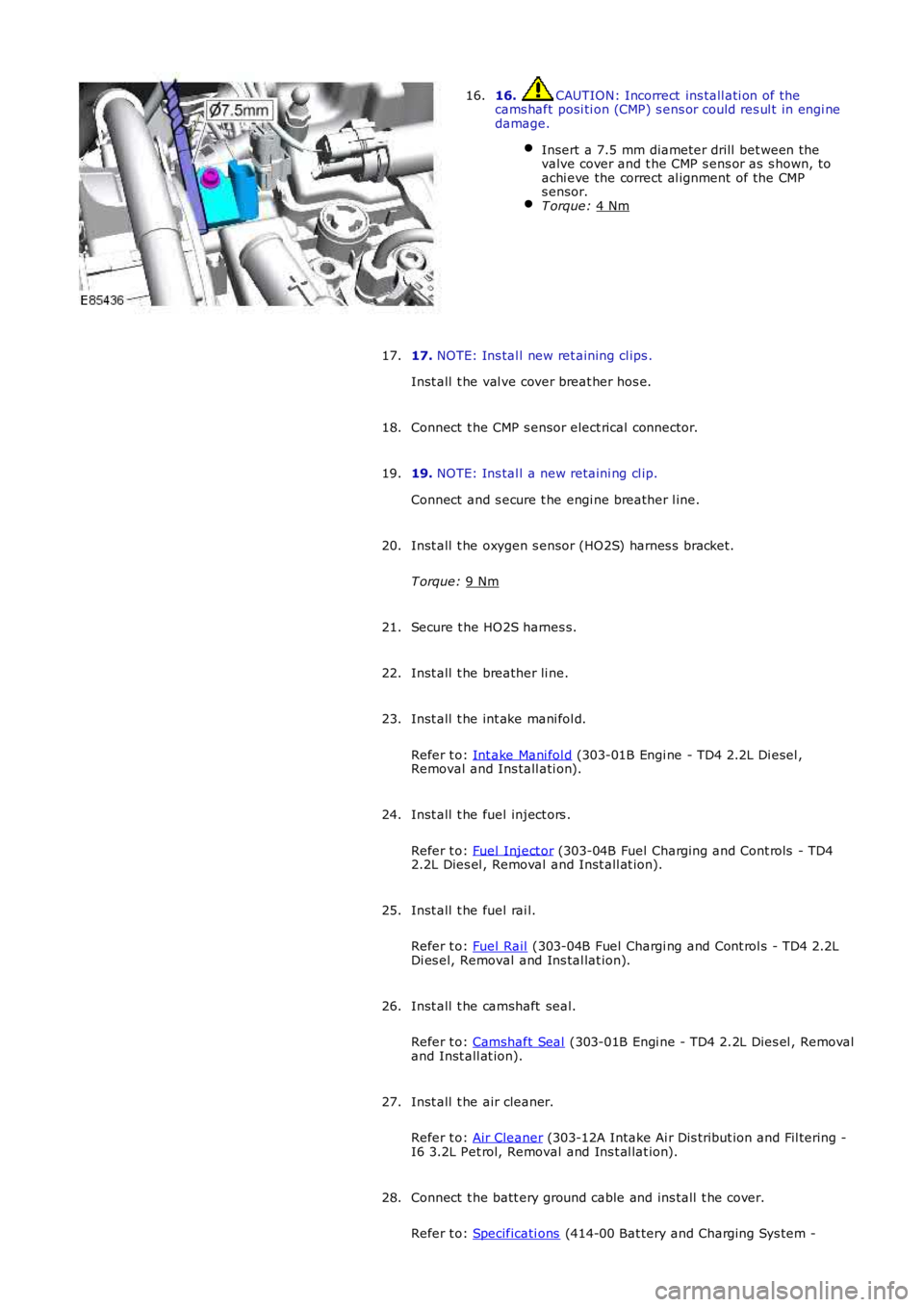
16. CAUTION: Incorrect ins tall ati on of the
cams haft posi ti on (CMP) s ens or could res ul t in engi ne
damage.
Insert a 7.5 mm diameter drill bet ween the
valve cover and t he CMP s ens or as s hown, to
achi eve the correct al ignment of the CMP
s ensor. T orque:
4 Nm 16.
17. NOTE: Ins tal l new ret aining cl ips .
Inst all t he val ve cover breat her hos e.
17.
Connect t he CMP s ensor elect rical connector.
18.
19. NOTE: Ins tal l a new retaini ng cl ip.
Connect and s ecure t he engi ne breather l ine.
19.
Inst all t he oxygen s ensor (HO2S) harnes s bracket.
T orque: 9 Nm 20.
Secure t he HO2S harnes s.
21.
Inst all t he breather li ne.
22.
Inst all t he int ake mani fol d.
Refer t o: Int ake Mani fol d (303-01B Engi ne - TD4 2.2L Di esel ,
Removal and Ins tall ati on).
23.
Inst all t he fuel inject ors .
Refer t o: Fuel Inject or (303-04B Fuel Charging and Cont rols - TD4
2.2L Dies el , Removal and Inst all at ion).
24.
Inst all t he fuel rai l.
Refer t o: Fuel Rail (303-04B Fuel Chargi ng and Cont rol s - TD4 2.2L
Di es el, Removal and Ins tal lat ion).
25.
Inst all t he camshaft seal.
Refer t o: Camshaft Seal (303-01B Engi ne - TD4 2.2L Dies el , Removal
and Inst all at ion).
26.
Inst all t he air cleaner.
Refer t o: Air Cleaner (303-12A Intake Ai r Dis tribut ion and Fil tering -
I6 3.2L Pet rol, Removal and Ins t al lat ion).
27.
Connect t he batt ery ground cable and ins tall t he cover.
Refer t o: Specificati ons (414-00 Bat tery and Charging Sys tem -
28.
Page 867 of 3229

Stage 1:
Stage 2:
Stage 3: Make s ure to ins tal l a gas ket of the correct thicknes s
Make s ure that t he gasket is correctl y located.
Inst all a new cyli nder head gas ket .
6. W ARNING: Thi s s tep requi res t he aid of anot her t echni ci an.
CAUTION: Make s ure that t he component is correct ly locat ed
on t he locati ng dowels .
Inst all t he cyl inder head.
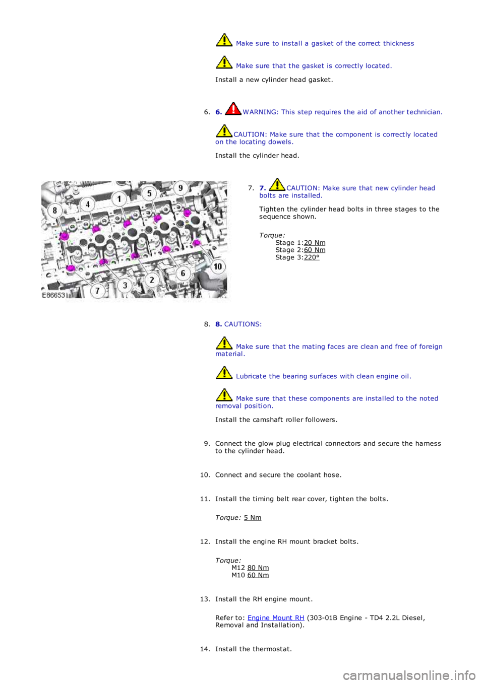
6. 7. CAUTION: Make s ure that new cylinder head
bolt s are ins tal led.
Tight en the cyli nder head bolt s in three s tages t o the
s equence s hown.
T orque: 20 Nm 60 Nm
220°7.
8. CAUTIONS: Make s ure that t he mat ing faces are clean and free of foreign
mat eri al . Lubri cat e t he bearing s urfaces wit h clean engine oil .
Make s ure that t hes e component s are ins tal led t o t he noted
removal posi ti on.
Inst all t he camshaft roll er foll owers .
8.
Connect t he glow pl ug electrical connect ors and s ecure t he harnes s
t o t he cyl inder head.
9.
Connect and s ecure t he cool ant hos e.
10.
Inst all t he ti ming bel t rear cover, ti ght en t he bol ts .
T orque: 5 Nm 11.
Inst all t he engi ne RH mount bracket bol ts .
T orque: M12 80 Nm M10
60 Nm 12.
Inst all t he RH engine mount .
Refer t o: Engi ne Mount RH (303-01B Engi ne - TD4 2.2L Di esel ,
Removal and Ins tall ati on).
13.
Inst all t he thermost at.
14.
Page 905 of 3229

Stage 1:
Stage 2: Make s ure that new bolt s are ins t al led.
Inst all t he dri ves haft .
T orque: 40 Nm Inst all t he cool ant expans i on tank.
T orque: 10 Nm 9.
Secure t he engi ne wiring harnes s .
T orque: 10 Nm 10.
11. CAUTION: Extreme cleanli nes s mus t be exercis ed when
handl ing t hese components .
Connect t he fuel li nes .
11.
Connect t he cool ant t op hos e.
12.
Connect t he cool ant bot tom hos e.
13.
Connect t he cool ing fan electrical connect or.
14.
Inst all t he RH halfs haft and s upport bracket.
T orque: 25 Nm 15.
Inst all t he LH halfshaft.
16.
W it h ass i st ance, i ns t all the hal fs haft t o t he hub.
17.
Inst all t he hal fs haft s .
T orque: 45 Nm 80°18.
19. CAUTION: A new O-ring s eal is t o be ins tall ed.
• NOTE: Lubri cat e t he O-ring s eals wit h clean refri gerant oil.
Connect t he A/C compress or high-press ure refri gerant line.
T orque: 24 Nm 19.
20. CAUTION: A new O-ring s eal is t o be ins tall ed.
• NOTE: Lubri cat e t he O-ring s eals wit h clean refri gerant oil.
Connect t he A/C compress or low-pres s ure refrigerant li ne.
T orque: 24 Nm 20.
Connect t he low pres sure li ne t o t he power s t eering pump.
21.
Page 906 of 3229

22. CAUTION: A new O-ring s eal is t o be ins tall ed.
Connect t he high-press ure power s t eering l ine t o t he power st eeri ng
pump.
T orque: 24 Nm 22.
Secure t he power s t eering hi gh-pres s ure l ine.
T orque: 10 Nm 23.
Inst all t he gear s elector cables .
24.
Connect t he brake boost er vacuum hos e.
25.
Connect t he ECM elect rical connectors .
26.
Inst all t he int ake ai r duct .
27.
Inst all t he charge air cool er inlet pipe.
T orque: 10 Nm 28.
Inst all t he front subframe.
Refer t o: Front Subframe (502-00 Uni -Body, Subframe and Mount ing
Syst em, Removal and Ins tall ati on).
29.
Inst all t he lower engi ne s tabil izer bar.
Refer t o: Engi ne Lower Support Ins ulat or (303-01A Engine - I6 3.2L
Petrol, Removal and Ins tall ati on).
30.
Inst all t he cat alyti c convert er.
Refer t o: Cat alyt ic Converter - Vehicles W it hout : Di es el Part iculate Fil ter (DPF) (309-00B Exhaus t Syst em - TD4 2.2L Di es el, Removal
and Inst all at ion).
31.
Refi ll and bleed t he cool ing s ys tem.
Refer t o: Cool ing Sys tem Drai ni ng, Fi lli ng and Bleeding (303-03B
Engine Cooli ng - TD4 2.2L Di esel , General Procedures ).
32.
Inst all t he air cleaner as s embly.
Refer t o: Air Cleaner (303-12A Intake Ai r Dis tribut ion and Fil tering -
I6 3.2L Pet rol, Removal and Ins t al lat ion).
33.
Inst all t he bat t ery t ray.
Refer t o: Bat t ery Tray (414-01 Bat tery, Mount ing and Cables ,
Removal and Ins tall ati on).
34.
Inst all t he plenum chamber access panel.
Refer t o: Plenum Chamber (412-01 Cl imat e Control, Removal and
Inst all at ion).
35.
Page 924 of 3229
Publi s hed: 11-May-2011
Engine Cooling - I6 3.2L Petrol - Radiator
Removal and Inst all ati on
Removal
1. W ARNING: Make sure t o s upport the vehicle wit h axles tands .
Rais e and s upport t he vehi cl e.
1.
Remove t he bumper armature.
Refer t o: Front Bumper (501-19 Bumpers , Removal and Ins tall ati on).
2.
Drai n t he cool ing s ys tem.
Refer t o: Cool ing Sys tem Drai ni ng, Fi lli ng and Bleeding (303-03AEngine Cooli ng - I6 3.2L Petrol, General Procedures).
3.
4.
Releas e power st eeri ng cooler and s ecure as ide.5.
Page 928 of 3229
Connect and s ecure t he electrical connect or.
6.
Inst all t he aut omat ic t rans mis s ion flui d cool er.
7.
Connect t he cool ant t op hos e.
8.
Connect t he cool ant l ower hos e.
9.
Inst all t he PAS cool er and t ight en the bol ts .
T orque: 10 Nm 10.
Inst all t he air defl ect or.
11.
Fil l and bl eed the cooli ng s ys t em.
Refer t o: Cool ing Sys tem Drai ni ng, Fi lli ng and Bleeding (303-03A
Engine Cooli ng - I6 3.2L Petrol, General Procedures).
12.
Inst all t he bumper.
Refer t o: Front Bumper (501-19 Bumpers , Removal and Ins tall ati on).
13.
Page 931 of 3229
Di sconnect t he cool ing fan cont rol electrical connect or.
10.
Releas e t he cool ing fan wiring harnes s .
11. Remove t he cool ing fan ass embly.
12.
Installation Inst all t he cool ing fan ass embly.
1.
Inst all t he A/C compress or.
T orque: 25 Nm 2.
Inst all t he A/C compress or, upper s upport bracket.
T orque: M10 45 Nm M8
25 Nm M6
10 Nm 3.
Inst all t he acces sory dri ve bel t.
4.
Inst all t he A/C compress or, l ower support bracket.
T orque: 25 Nm 5.
Inst all t he A/C li ne support bracket.
T orque: 10 Nm 6.
Secure t he A/C pipes.
7.
Secure t he cool ing fan harness .
8.