2006 LAND ROVER FRELANDER 2 ECU
[x] Cancel search: ECUPage 940 of 3229
2-Gas ket
3-Coolant pump
The cent ri fugal type coolant pump is mount ed at t he front of t he engine and s ecured wit h 7 bol ts . The pump i s direct lydri ven by the t oothed cams haft belt and circul ates coolant through t he cylinder block and cyl inder head, cool ing s ys temand heat er circuit .
The cool ant pump is able to del iver cool ant at a rate of 215 lit ers /min (57 US gal lons /min) at 2.8 bar (41 psi ), creat ing amaximum external s yst em press ure of 2.0 bar (30 psi ).
A l arge di amet er cool ant rail located on the Ri ght -Hand (RH) s ide of t he engine connects the rear of t he coolant pumphous i ng to the t hermal control modul e outl et . A connect ion on t he cool ant rail at t he cool ant pump hous ing end provi dest he coolant return from t he EGR cooler.
THERMAL CONTROL MODULE
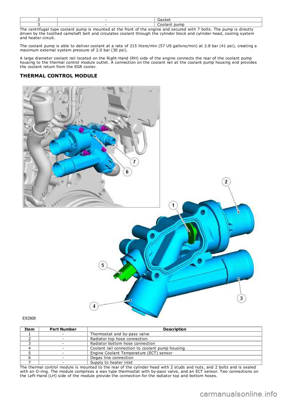
ItemPart NumberDescription
1-Thermos t at and by-pass val ve
2-Radiat or top hos e connecti on3-Radiat or bot tom hose connect ion
4-Coolant rai l connect ion to coolant pump hous ing
5-Engine Coolant Temperat ure (ECT) sens or6-Degas l ine connecti on
7-Supply t o heater i nl et
The t hermal cont rol module i s mounted to t he rear of t he cyl inder head wit h 2 s t uds and nut s , and 2 bolt s and is s ealedwit h an O-ring. The module compri s es a wax t ype thermos t at wit h by-pas s valve, and an ECT s ens or. Two connect ions ont he Left-Hand (LH) s i de of the module provide t he connecti on for t he radi at or top and bot tom hoses .
Page 941 of 3229
The wax-t ype thermost at locates i n t he top hos e connecti on t o t he radiat or. A l arge di ameter connecti on at the RH lowers ide connect s the modul e t o t he coolant rail. Two smal l diamet er out lets on the front of t he module provi de t he connect ionfor a supply hos e t o t he heat er mat rix, and a degas l ine t o t he cool ant reservoi r.
The t hermal cont rol module promotes rapi d warming of t he engine t o normal operat ing t emperature by clos ing t he returncool ant connect ion from the engi ne to the radiator. During the engine warmi ng period, t he thermost at is cl os ed and t heby-pas s val ve is open. The by-pass port all ows cool ant t o circul ate t hrough t he closed engi ne circuit vi a t he coolant pump,climate control heat er ci rcuit and EGR cooler.
As t he cool ant t emperat ure i ncreas es , the t hermos t at is opened and the by-pas s valve i s clos ed. The hot cool ant ret urningfrom the engine i s all owed to fl ow from the t hermal cont rol module to the radiator, through the open t hermos tat and t ophose connect ion. Return cool ant from t he radiat or fl ows through the bot tom hos e connect ion t o t he cool ant pump, via thecool ant rail .
The t hermos tat commences opening at 83°C (181°F), and i s ful ly open at 91°C (196°F).
The ECT s ens or is locat ed i n t he thermal control modul e and s ecured in the hous ing wi th a clip. The ECT s ens or provi desan engine coolant temperat ure si gnal t o t he Engi ne Control Module (ECM). The si gnal i s us ed by the ECM to cont rol t heoperati on of the 2 cool ing fans .For addit ional informat ion, refer t o: Electroni c Engi ne Controls - 2.2L Dies el (303-14 El ect ronic Engine Cont rols - 2.2LDies el, Des cript ion and Operat ion).
The ECM al so communi cat es the ECT si gnal on t he high speed Controll er Area Network (CAN) bus t o t he Central Junct ionBox (CJB). The CJB t rans mi ts t he ECT s ignal via t he medium s peed CAN bus to the ins trument cl us t er, for di spl ay on thecool ant t emperat ure gage.For addit ional informat ion, refer t o: Ins t rument Clus ter (413-01 Inst rument Cl us t er, Des cript ion and Operat ion).
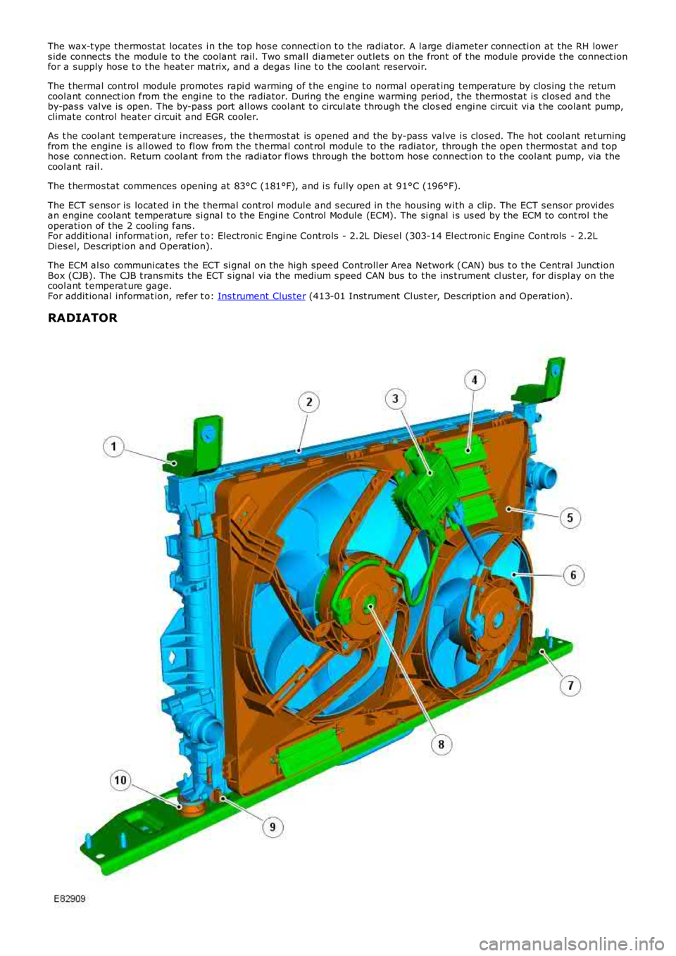
RADIATOR
Page 942 of 3229
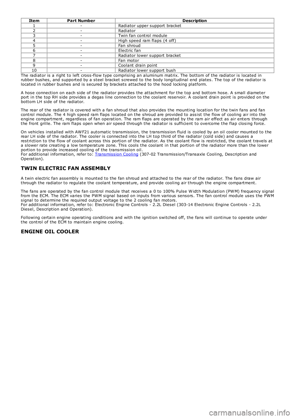
ItemPart NumberDescription
1-Radi ator upper s upport bracket
2-Radi ator3-Twin fan cont rol module
4-High s peed ram fl aps (4 off)
5-Fan shroud6-Elect ric fan
7-Radi ator lower s upport bracket
8-Fan motor9-Cool ant drain point
10-Radi ator lower s upport bus h
The radi at or is a ri ght t o l eft cros s -flow type compri si ng an alumi num mat ri x. The bot tom of the radiat or i s l ocated inrubber bus hes , and support ed by a s t eel bracket s crewed to the body l ongi tudinal end plates . The t op of the radiator i slocated i n rubber bushes and i s s ecured by bracket s at tached to the hood l ocking pl at form.
A hos e connecti on on each s ide of t he radiat or provi des the at t achment for t he t op and bot t om hos e. A s mall diamet erport i n t he top RH s ide provi des a degas l ine connect ion t o t he cool ant reservoi r. A coolant drai n point i s provided on t hebott om LH si de of the radiat or.
The rear of t he radiat or is covered wit h a fan s hroud t hat als o provides t he mounti ng locati on for t he t win fans and fancont rol module. The 4 hi gh s peed ram flaps l ocat ed on t he s hroud are provi ded to assi st t he flow of cooling ai r int o t heengi ne compart ment , regardl ess of fan operat ion. The ram fl aps are operat ed by the ram air effect as ai r ent ers throught he front gril le. The ram fl aps open when air s peed through t he radi at or is suffi ci ent t o overcome t he flap clos ing force.
On vehicles i nst all ed wit h AW F21 aut omati c transmis si on, the t rans mis s ion flui d is cooled by an oil cool er mount ed t o t herear LH s i de of the radi ator. The cooler i s connected i nto t he LH t op t hird of the radiator (col d s ide) and caus es ares t ri ct ion t o t he flow of coolant across this porti on of the radiat or. As t he cool ant flow is rest ri cted, the coolant t ravels ata s lower rate creat ing a low temperat ure zone. Thi s cool s t he cool ant i n t hat porti on of the radiator more t han the l owerport ion t o provi de increas ed cooli ng of the trans mi s si on oil .For addit ional informat ion, refer t o: Trans mis s ion Cooli ng (307-02 Trans mis s ion/Trans axle Cooli ng, Des cri pti on andOperat ion).
TWIN ELECTRIC FAN ASSEMBLY
A t win electric fan ass embl y is mount ed t o the fan s hroud and at tached to the rear of the radi ator. The fans draw airt hrough the radiator t o regul at e t he cool ant temperat ure, and provide cooli ng air t hrough the engi ne compartment .
The fans are operated by the fan cont rol module that receives a 0 to 100% Puls e W idth Modulati on (PW M) frequency s ignalfrom the ECM. The ECM varies t he PW M si gnal bas ed on inputs from vari ous sens ors . The fan cont rol module us es t he PW Ms ignal to det ermi ne the required out put vol tage t o t he 2 cooling fan mot ors .For addit ional informat ion, refer t o: Electroni c Engi ne Controls - 2.2L Dies el (303-14 El ect ronic Engine Cont rols - 2.2LDies el, Des cript ion and Operat ion).
Followi ng certai n engine operat ing condi ti ons and wit h t he ignit ion s wi tched off, the fans wil l cont inue t o operate undert he cont rol of the ECM to maint ai n engine cooling.
ENGINE OIL COOLER
Page 963 of 3229
Inst all t he thermost at hous i ng.
Connect t he engi ne cool ant t empret ure (ECT) s ens or
electrical connect or. Secure t he cool ant mani fold to thermost at hous ing pi pe.
T orque: 8 Nm 3.
Inst all t he s tuds .
T orque: 7 Nm 4.
Secure t he thermost at hous i ng.
T orque: 8 Nm 5.
Connect t he heat er out let pi pe.
6.
Secure t he wiring harnes s s upport bracket .
T orque: 8 Nm 7.
Connect t he cool ant hos es to the thermos t at hous ing.
8.
Inst all t he engi ne cover.
Refer t o: Engi ne Cover - TD4 2.2L Dies el (501-05 Interior Tri m and
Ornament ati on, Removal and Ins tal lat ion).
9.
Inst all t he air cleaner as s embly.
Refer t o: Air Cleaner (303-12A Intake Ai r Dis tribut ion and Fil tering -
I6 3.2L Pet rol, Removal and Ins t al lat ion).
10.
Connect t he batt ery ground cable.
Refer t o: Specificati ons (414-00 Bat tery and Charging Sys tem -
General Informat ion, Specificati ons).
11.
Refi ll and bleed t he cool ing s ys tem.
Refer t o: Cool ing Sys tem Drai ni ng, Fi lli ng and Bleeding (303-03B
Engine Cooli ng - TD4 2.2L Di esel , General Procedures ).
12.
Page 967 of 3229
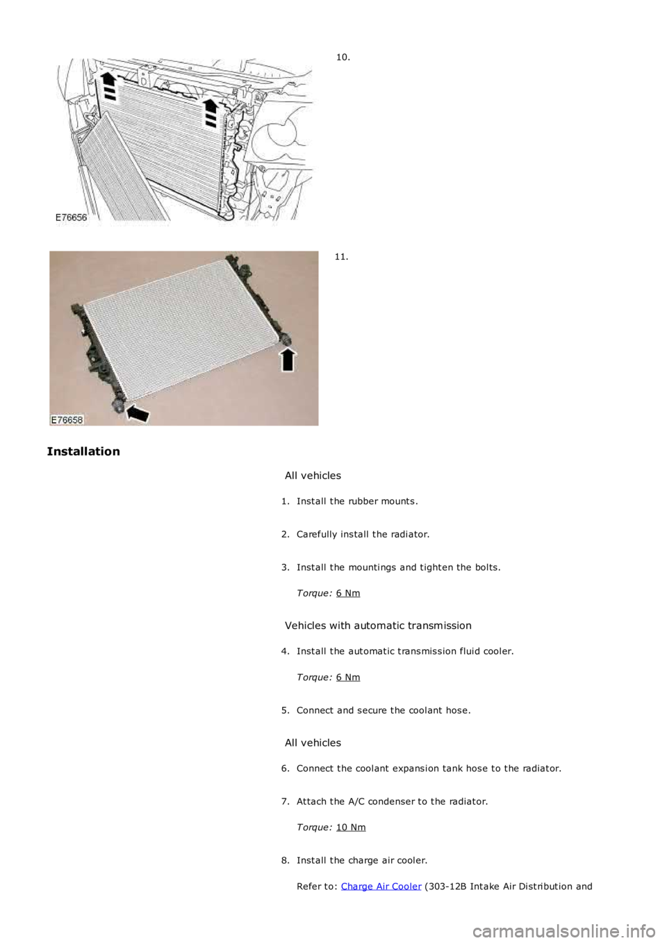
10.
11.
Installation All vehicles
Inst all t he rubber mount s .
1.
Carefully ins tall t he radi ator.
2.
Inst all t he mounti ngs and t ight en the bol ts .
T orque: 6 Nm 3.
Vehicles with automatic transm ission Inst all t he aut omat ic t rans mis s ion flui d cool er.
T orque: 6 Nm 4.
Connect and s ecure t he cool ant hos e.
5.
All vehicles Connect t he cool ant expans i on tank hos e t o t he radiat or.
6.
At tach t he A/C condenser t o t he radiat or.
T orque: 10 Nm 7.
Inst all t he charge air cool er.
Refer t o: Charge Air Cooler (303-12B Int ake Air Di st ri but ion and
8.
Page 990 of 3229
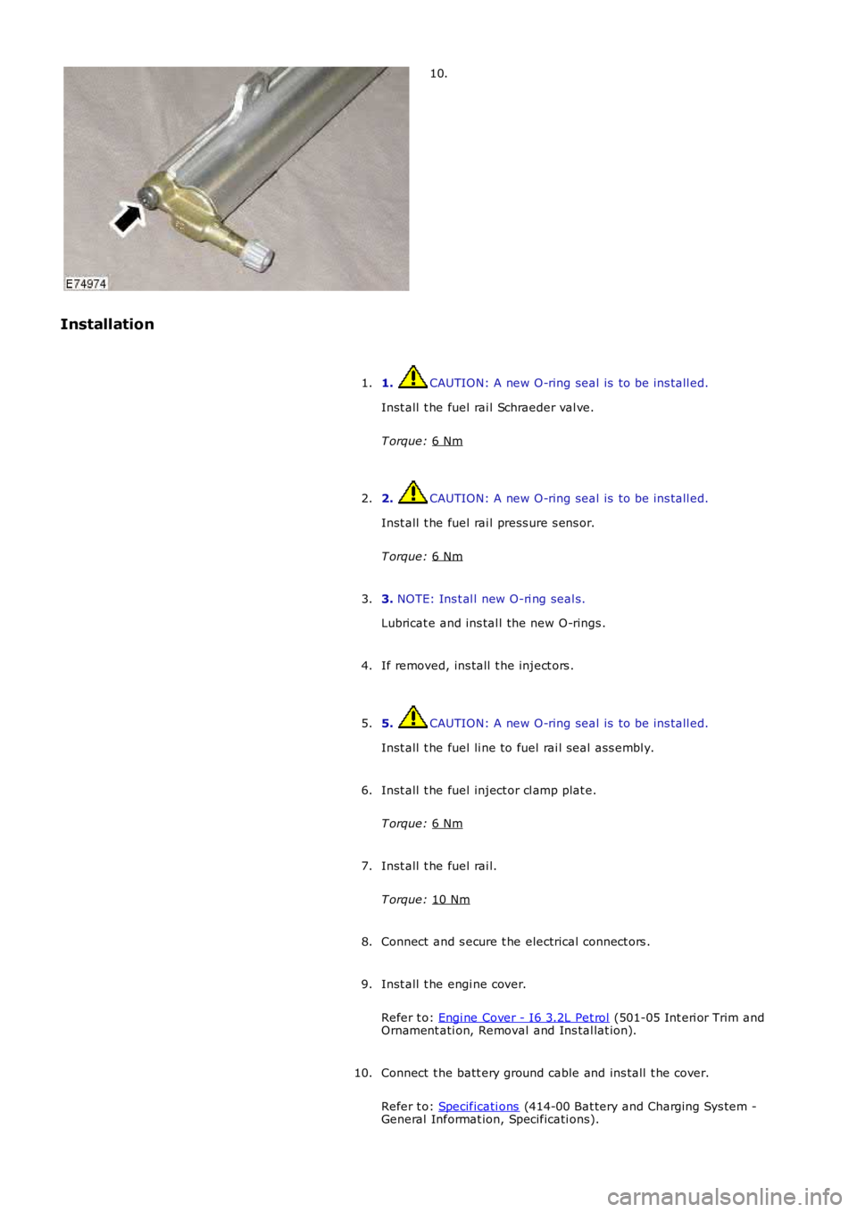
10.
Installation 1. CAUTION: A new O-ring seal is to be ins tall ed.
Inst all t he fuel rai l Schraeder val ve.
T orque: 6 Nm 1.
2. CAUTION: A new O-ring seal is to be ins tall ed.
Inst all t he fuel rai l press ure s ens or.
T orque: 6 Nm 2.
3. NOTE: Ins t al l new O-ri ng seal s.
Lubricat e and ins tal l the new O-rings .
3.
If removed, ins tall t he inject ors .
4.
5. CAUTION: A new O-ring seal is to be ins tall ed.
Inst all t he fuel li ne to fuel rai l seal ass embl y.
5.
Inst all t he fuel inject or cl amp plat e.
T orque: 6 Nm 6.
Inst all t he fuel rai l.
T orque: 10 Nm 7.
Connect and s ecure t he electrical connect ors .
8.
Inst all t he engi ne cover.
Refer t o: Engi ne Cover - I6 3.2L Pet rol (501-05 Int eri or Trim and
Ornament ati on, Removal and Ins tal lat ion).
9.
Connect t he batt ery ground cable and ins tall t he cover.
Refer t o: Specificati ons (414-00 Bat tery and Charging Sys tem -
General Informat ion, Specificati ons).
10.
Page 992 of 3229
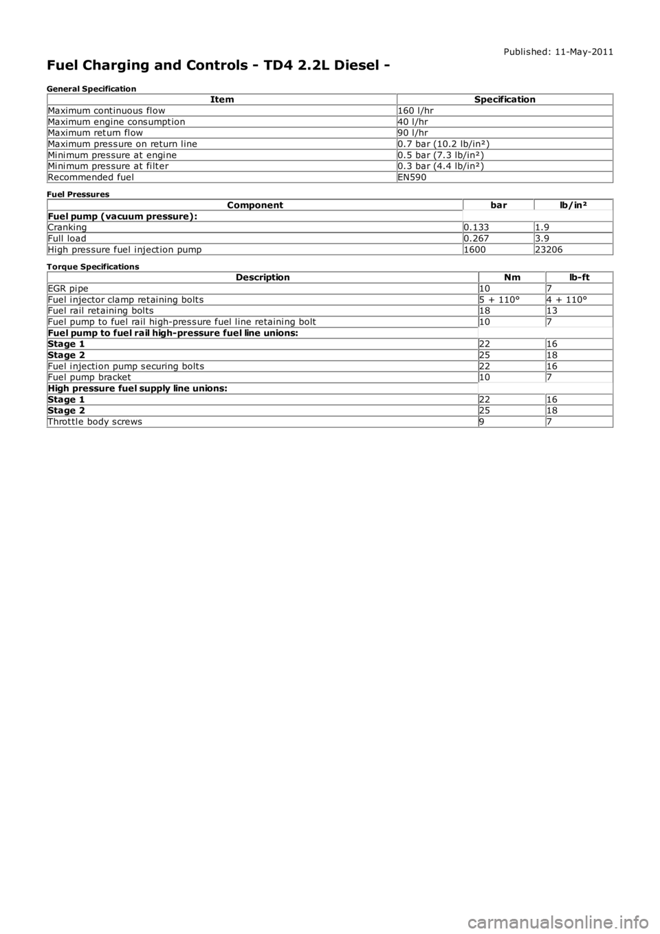
Publi s hed: 11-May-2011
Fuel Charging and Controls - TD4 2.2L Diesel -
General SpecificationItemSpecification
Maximum cont inuous fl ow160 l /hr
Maximum engine cons umpt ion40 l /hrMaximum ret urn fl ow90 l /hr
Maximum pres s ure on return l ine0.7 bar (10.2 lb/in²)
Mi ni mum pres sure at engi ne0.5 bar (7.3 lb/in²)Mi ni mum pres sure at fi lt er0.3 bar (4.4 lb/in²)
Recommended fuelEN590
Fuel Pressures
Componentbarlb/in²
Fuel pump (vacuum pressure):Cranking0.1331.9
Full load0.2673.9
Hi gh pres sure fuel i nject ion pump160023206
Torque SpecificationsDescriptionNmlb-ft
EGR pi pe107
Fuel i njector clamp ret ai ning bolt s5 + 110°4 + 110°Fuel rail ret aini ng bol ts1813
Fuel pump to fuel rail hi gh-pres s ure fuel l ine retaini ng bolt107
Fuel pump to fuel rail high-pressure fuel line unions:Stage 12216
Stage 22518
Fuel i njecti on pump s ecuring bolt s2216Fuel pump bracket107
High pressure fuel supply line unions:
Stage 12216Stage 22518
Throt tl e body s crews97
Page 998 of 3229
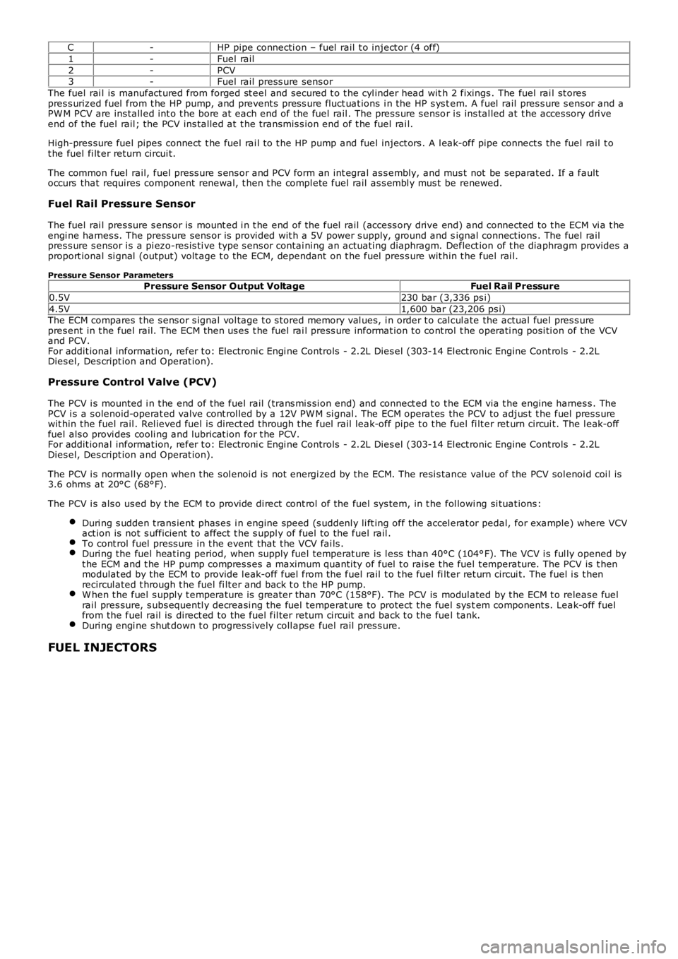
C-HP pipe connecti on – fuel rail t o inject or (4 off)
1-Fuel rail
2-PCV3-Fuel rail press ure sens or
The fuel rai l is manufact ured from forged st eel and secured t o t he cyl inder head with 2 fixings . The fuel rai l st orespres s urized fuel from t he HP pump, and prevent s pres s ure fluct uat ions i n the HP s ys tem. A fuel rail pres s ure s ens or and aPW M PCV are ins tall ed int o t he bore at each end of the fuel rail . The pres s ure s ensor i s ins tal led at t he acces sory dri veend of the fuel rail ; the PCV ins tal led at t he transmis s ion end of t he fuel rai l.
High-pres sure fuel pipes connect t he fuel rai l t o t he HP pump and fuel inject ors . A l eak-off pipe connect s the fuel rail t ot he fuel fi lt er return circui t.
The common fuel rail, fuel press ure s ens or and PCV form an int egral as s embly, and mus t not be separat ed. If a faultoccurs that requires component renewal, t hen t he compl ete fuel rail as s embl y mus t be renewed.
Fuel Rail Pressure Sensor
The fuel rai l pres sure s ens or is mount ed i n t he end of the fuel rail (access ory drive end) and connected to t he ECM vi a t heengi ne harnes s. The press ure sens or is provi ded wit h a 5V power s upply, ground and signal connect ions . The fuel railpres s ure s ensor i s a pi ezo-res is ti ve type s ens or contai ni ng an actuati ng diaphragm. Deflect ion of t he diaphragm provides aproport ional si gnal (output) volt age t o t he ECM, dependant on t he fuel pres s ure wit hin t he fuel rai l.
Pressure Sensor ParametersPressure Sensor Output VoltageFuel Rail Pressure
0.5V230 bar (3,336 ps i)
4.5V1,600 bar (23,206 ps i)The ECM compares t he s ens or s ignal vol tage t o s tored memory val ues, i n order t o cal cul ate the actual fuel pres s urepres ent in t he fuel rail. The ECM then us es t he fuel rai l press ure informat ion t o cont rol t he operati ng posi ti on of the VCVand PCV.For addit ional informat ion, refer t o: Electroni c Engi ne Controls - 2.2L Dies el (303-14 El ect ronic Engine Cont rols - 2.2LDies el, Des cript ion and Operat ion).
Pressure Control Valve (PCV)
The PCV i s mounted i n t he end of the fuel rail (trans mi s si on end) and connect ed t o the ECM via t he engine harnes s . ThePCV i s a s olenoid-operat ed valve cont rol led by a 12V PW M si gnal . The ECM operat es the PCV to adjus t t he fuel pres s urewit hin the fuel rail . Rel ieved fuel is direct ed through t he fuel rail leak-off pipe t o t he fuel fi lt er ret urn circui t. The l eak-offfuel als o provi des cooli ng and lubricat ion for t he PCV.For addit ional informat ion, refer t o: Electroni c Engi ne Controls - 2.2L Dies el (303-14 El ect ronic Engine Cont rols - 2.2LDies el, Des cript ion and Operat ion).
The PCV i s normall y open when t he s ol enoi d is not energi zed by the ECM. The resi s tance val ue of the PCV sol enoi d coi l is3.6 ohms at 20°C (68°F).
The PCV i s als o us ed by t he ECM t o provide di rect cont rol of the fuel sys tem, in t he fol lowi ng si tuat ions :
Duri ng s udden t rans ient phas es i n engine s peed (s uddenl y li ft ing off the accel erat or pedal, for example) where VCVact ion is not s ufficient to affect t he s uppl y of fuel to the fuel rail .To cont rol fuel press ure in t he event that the VCV fai ls .Duri ng the fuel heat ing period, when supply fuel temperat ure is l ess than 40°C (104°F). The VCV i s ful ly opened byt he ECM and t he HP pump compres s es a maximum quanti ty of fuel t o rais e t he fuel t emperature. The PCV is t henmodulat ed by the ECM to provide l eak-off fuel from the fuel rail t o t he fuel fi lt er ret urn circui t. The fuel i s t henrecircul ated t hrough t he fuel fi lt er and back t o t he HP pump.W hen t he fuel s uppl y t emperature is greater t han 70°C (158°F). The PCV is modul ated by t he ECM t o releas e fuelrai l pres sure, s ubs equentl y decreasi ng the fuel temperat ure to protect the fuel sys tem component s. Leak-off fuelfrom the fuel rail is direct ed to the fuel fil ter return ci rcuit and back t o the fuel tank.Duri ng engi ne s hut down t o progres s ively coll aps e fuel rail pres s ure.
FUEL INJECTORS