Page 1669 of 3229

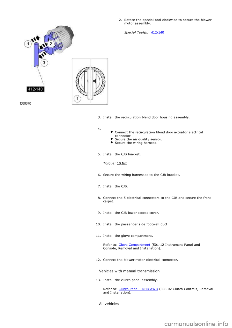
Rotat e t he s pecial t ool clockwis e t o s ecure t he blower
mot or as s embly.
Speci al Tool (s ): 412-140 2.
Inst all t he recircul at ion bl end door hous ing as s embl y.
3.
Connect t he recircul ati on blend door act uat or el ect ri cal
connector. Secure t he air qualit y s ensor.
Secure t he wiring harnes s .4.
Inst all t he CJB bracket .
T orque: 10 Nm 5.
Secure t he wiring harnes s es to the CJB bracket.
6.
Inst all t he CJB.
7.
Connect t he 5 elect rical connectors to the CJB and s ecure t he front
carpet.
8.
Inst all t he CJB lower acces s cover.
9.
Inst all t he pas s enger s ide footwel l duct .
10.
Inst all t he glove compartment .
Refer t o: Glove Compart ment (501-12 Ins trument Panel and
Consol e, Removal and Ins t al lat ion).
11.
Connect t he blower mot or el ect ri cal connector.
12.
Vehicles with manual transmission Inst all t he cl utch pedal as s embly.
Refer t o: Clutch Pedal - RHD AW D (308-02 Clut ch Cont rol s, Removal
and Inst all at ion).
13.
All vehicles
Page 1689 of 3229
Remove t he evaporat or core.23.
Remove any debris from t he heat er core and evaporator corehousi ng.24.
Installation
Apply t he foam s trips from t he service kit t o t heevaporator core.1.
Inst all t he evaporat or core.2.
Inst all t he s ervice door.Secure t he 4 cli ps.Inst all t he 4 s crews .
3.Inst all t he pol len fil ter cover.4.
Apply t he as phal t tape from the servi ce kit t o t hes ervice replacement evaporator pipes .5.
6. CAUTION: Make s ure that all openi ngs are s ealed. Us e new6.
Page 1690 of 3229

blanking caps.
Remove t he TXV as sembl y from t he s ervice replacement evaporator
pipes .
Guide the s ervi ce replacement evaporator pi pes t hrough t he
bulkhead s o that approximat ely 20mm is vi s ible in t he engine
compart ment.
7.
Inst all t he TXV capt ive clampi ng plat e.
8. 9.
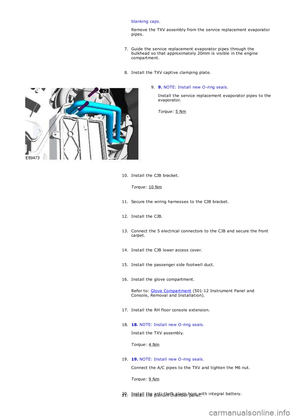
NOTE: Ins t al l new O-ri ng seal s.
Inst all t he s ervice repl acement evaporat or pipes t o the
evaporator.
T orque: 5 Nm 9.
Inst all t he CJB bracket .
T orque: 10 Nm 10.
Secure t he wiring harnes s es to the CJB bracket.
11.
Inst all t he CJB.
12.
Connect t he 5 elect rical connectors to the CJB and s ecure t he front
carpet.
13.
Inst all t he CJB lower acces s cover.
14.
Inst all t he pas s enger s ide footwel l duct .
15.
Inst all t he glove compartment .
Refer t o: Glove Compart ment (501-12 Ins trument Panel and
Consol e, Removal and Ins t al lat ion).
16.
Inst all t he RH floor cons ole ext ens ion.
17.
18. NOTE: Ins tal l new O-ring seals .
Inst all t he TXV as sembl y.
T orque: 4 Nm 18.
19. NOTE: Ins tal l new O-ring seals .
Connect t he A/C pipes t o the TXV and ti ght en t he M6 nut .
T orque: 9 Nm 19.
Inst all t he ant i-t heft alarm horn wit h i nt egral batt ery.
20.
Inst all t he plenum chamber panel.
21.
Page 1699 of 3229
Inst all t he s ervice door. Secure t he 4 cli ps.
Inst all t he 4 s crews .4.
Apply t he as phal t tape from the servi ce kit t o t he
s ervice replacement evaporator pipes .
5.
6. CAUTION: Make s ure that all openi ngs are s ealed. Us e new
blanking caps.
Remove t he TXV as sembl y from t he s ervice replacement evaporator
pipes .
6.
Guide the s ervi ce replacement evaporator pi pes t hrough t he
bulkhead s o that approximat ely 20mm is vi s ible in t he engine
compart ment.
7.
Inst all t he TXV capt ive clampi ng plat e.
8. 9.
NOTE: Ins t al l new O-ri ng seal s.
Inst all t he s ervice repl acement evaporat or pipes t o the
evaporator.
T orque: 5 Nm 9.
Page 1700 of 3229

Connect t he blower mot or el ect ri cal connector.
10.
11. NOTE: Ins tal l new O-ring seals .
Inst all t he TXV as sembl y.
T orque: 4 Nm 11.
12. NOTE: Ins tal l new O-ring seals .
Connect t he A/C pipes t o the TXV and ti ght en t he M6 nut .
T orque: 9 Nm 12.
Inst all t he RH floor cons ole ext ens ion.
13.
Inst all t he brake pedal as s embly.
T orque: 25 Nm 14.
Inst all t he brake pedal clevis pi n.
15.
Connect t he s toplamp swit ch and speed cont rol deact ivat or s wi tch
electrical connect ors .
16.
Secure t he wiring harnes s t o t he brake pedal bracket.
17.
Inst all t he accelerat or pedal as sembl y.
Refer t o: Accelerat or Pedal (310-02 Accelerati on Cont rol , Removal
and Inst all at ion).
18.
Vehicles with automatic transm ission Inst all t he s econdary bulkhead cent er panel.
Refer t o: Secondary Bulkhead Cent er Panel - TD4 2.2L Dies el (501-02 Front End Body Panel s, Removal and Ins tal lati on).
19.
Vehicles with manual transmission Inst all t he cl utch pedal as s embly.
Refer t o: Clutch Pedal - RHD AW D (308-02 Clut ch Cont rol s, Removal
and Inst all at ion).
20.
All vehicles Inst all t he dri ver l ower ai r bag modul e s upport bracket .
T orque: 7 Nm 21.
Inst all t he s teeri ng col umn.
Refer t o: Steeri ng Column (211-04 St eering Col umn, Removal and
Inst all at ion).
22.
Recharge the A/C sys tem.
Refer t o: Air Condi ti oning (A/C) Sys tem Recovery, Evacuati on and Charging (412-00 Cl imat e Control Sys t em - General Informat ion,
23.
Page 1706 of 3229
Publi s hed: 11-May-2011
Climate Control - CondenserI6 3.2L Petrol
Removal and Inst all ati on
Removal
Remove t he cover and dis connect the bat tery ground cabl e.
Refer t o: Specificati ons (414-00 Bat tery and Charging Sys tem -
General Informat ion, Specificati ons).
1.
2. W ARNING: Make sure t o s upport the vehicle wit h axle
s tands .
Rais e and s upport t he vehi cl e.
2.
Recover t he A/C refrigerant .
Refer t o: Air Condi ti oning (A/C) Sys tem Recovery, Evacuati on and Charging (412-00 Cl imat e Control Sys t em - General Informat ion,
General Procedures).
3.
Remove t he front bumper.
Refer t o: Front Bumper (501-19 Bumpers , Removal and Ins tall ati on).
4. Remove t he radiat or ai r deflect or.
5. Releas e power st eeri ng cooler and s ecure as ide.
6.
Page 1725 of 3229
25.
Remove t he heat er core and evaporat or core housi ng.
26.
Installation Inst all t he heat er core and evaporat or core housi ng.
T orque: 7 Nm 1.
Inst all t he electric boost er heat er ass embly.
2.
Connect t he electric boos ter heat er core.
3.
Connect t he wiring harnes s t o t he heat er and evaporat or core
housi ng.
4.
Inst all both front footwell ducts .
5.
W it h ass i st ance, i ns t all the ins trument panel upper s ect ion.
6.
Inst all t he pas s enger ai r bag modul e s upport bracket bolt s .
T orque: 10 Nm 7.
Secure t he wiring harnes s t o t he ins t rument panel upper s ecti on.
8.
Connect t he pass enger ai r bag modul e electrical connect ors .
9.
Page 1726 of 3229

Inst all t he glove compartment .
Refer t o: Glove Compart ment (501-12 Ins trument Panel andConsol e, Removal and Ins t al lat ion).
10.
Inst all t he pas s enger s ide ins trument panel end trim panel .11.
Secure t he wiring harnes s s upport bracket .12.
Inst all t he cl imat e control as s embly.13.
Inst all t he audi o unit .14.
Inst all t he cent er speaker.15.
Inst all t he video dis play.
Refer t o: Video Dis play (415-01 Informati on and Entert ainmentSyst em, Removal and Ins tall ati on).
16.
Inst all both ins trument panel s peakers .17.
Inst all both upper t rim panels .18.
Connect t he in-vehi cl e t emperature s ens or electrical connect or.19.
Connect t he keyl es s s t art module elect rical connect or.20.
Inst all t he ins trument cl ust er.
Refer t o: Ins trument Clus ter (413-01 Ins t rument Clus t er, Removaland Inst all at ion).
21.
Inst all t he cl ocks pri ng.
Refer t o: Clocks pri ng (501-20B Supplement al Res t raint Sys tem,Removal and Ins tall ati on).
22.
Inst all t he ins trument panel.
Refer t o: Ins trument Panel - TD4 2.2L Dies el (501-12 Inst rumentPanel and Cons ole, Removal and Inst all at ion).Refer t o: Ins trument Panel - I6 3.2L Pet rol (501-12 Ins t rument Paneland Consol e, Removal and Ins t al lat ion).
23.
Connect t he batt ery ground cable.
Refer t o: Specificati ons (414-00 Bat tery and Charging Sys tem -General Informat ion, Specificati ons).
24.
Return t he s teeri ng col umn t o i ts original posi ti on.25.