2006 LAND ROVER FRELANDER 2 ECU
[x] Cancel search: ECUPage 1829 of 3229
Publi s hed: 11-May-2011
Battery, Mounting and Cables - Battery and Cables
Des cript ion and Operat ion
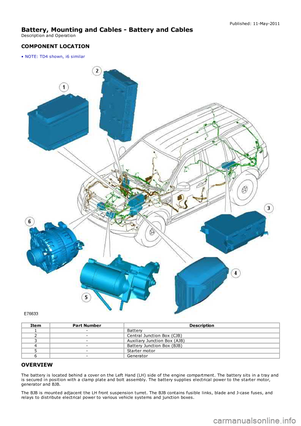
COMPONENT LOCATION
• NOTE: TD4 s hown, i6 s imil ar
ItemPart NumberDescription1-Batt ery
2-Central Junct ion Box (CJB)
3-Auxili ary Junct ion Box (AJB)4-Batt ery Junct ion Box (BJB)
5-Starter mot or
6-Generator
OVERVIEW
The batt ery i s located behind a cover on t he Left Hand (LH) si de of the engine compart ment . The bat tery s it s in a t ray andis secured i n pos it ion wi th a clamp pl at e and bolt as s embly. The batt ery s upplies elect ri cal power to the s t art er motor,generator and BJB.
The BJB is mount ed adjacent t he LH front s us pens ion t urret. The BJB cont ains fusi ble l inks , bl ade and J-case fus es, andrel ays to di st ribute el ect ri cal power to various vehicle s ys tems and junct ion boxes .
Page 1853 of 3229
1. CAUTION: Make s ure that the mati ng faces are cl ean and
free of foreign mat eri al.
Inst all t he generat or.
1.
Inst all t he 2 generator bolt s .
T orque: 48 Nm 2.
Inst all t he acces sory dri ve bel t idl er pull ey.
T orque: 48 Nm 3.
Inst all t he acces sory dri ve bel t idl er pull ey dust cap.
4.
Connect t he generator electrical connect or.
5.
Connect t he batt ery cable t o t he generator.
T orque: 24 Nm 6.
At tach t he power s t eering flui d res ervoir.
7.
8. CAUTION: Make s ure that the mati ng faces are cl ean and
free of foreign mat eri al.
Inst all t he power s t eering pump.
T orque: 24 Nm 8.
Inst all t he fuel fi lt er support bracket.
T orque: 20 Nm 9.
At tach t he oil level indicator t ube to the fuel fil ter s upport bracket .
T orque: 10 Nm 10.
Inst all t he inner fuel fi lt er shi el d.
11.
Secure t he cool ant t op hos e.
12.
Inst all t he acces sory dri ve bel t.
Refer t o: Acces sory Dri ve Belt (303-05B Acces sory Drive - TD4 2.2L
Di es el, Removal and Ins tal lat ion).
13.
Inst all t he engi ne undershi eld.
Refer t o: Engi ne Unders hi eld (501-02 Front End Body Panel s ,
Removal and Ins tall ati on).
14.
Inst all t he fuel fi lt er.
Refer t o: Fuel Fil ter (310-01B Fuel Tank and Lines - TD4 2.2L Dies el ,
Removal and Ins tall ati on).
15.
Page 1923 of 3229

vent il ati on of the headlamp whi le prevent ing t he i ngress of wat er.
The headl amps can be quickl y removed for bul b repl acement due t o t he uni que 'Rail Lock' s yst em. Headl amp acces srequires t he removal of 2 bol ts securi ng the headlamp to the bonnet cl osi ng panel . A l ocking l ever at t he rear of theheadl amp can t hen be li ft ed, releasi ng a l ocking tab at t he base of the headlamp body. The headl amp can then be pul ledforward on the rail and, aft er di sconnect ion of t he harness connect or, removed from t he vehi cl e. The 'Rail Lock' s ys t emensures that t he headl amp ali gnment i s not compromis ed duri ng t he removal proces s .
Each headlamp has two access covers at t he rear. The larger cover requi res t he l ocking l ever t o be released from i ts gui des lot s to allow acces s to the cover. The cover can t hen be removed by rel easi ng 2 t abs to al low the hi gh and low beambulbs t o be changed. The circular rubber cover i s a pus h fi t onto t he rear of t he lamp ass embly. Removal of t he cover givesacces s t o the si de lamp and turn s ignal indicator bulbs .
On NAS vehicl es , t he s ide l amp is col ored orange. The s ide l amp lens i s desi gned so that li ght from t he s ide l amp bulbals o i ll uminates t he orange colored reflect or area at t he s ide of t he lamp wit hout the need for an addit ional bulb.
Halogen Headlamps
Page 1926 of 3229
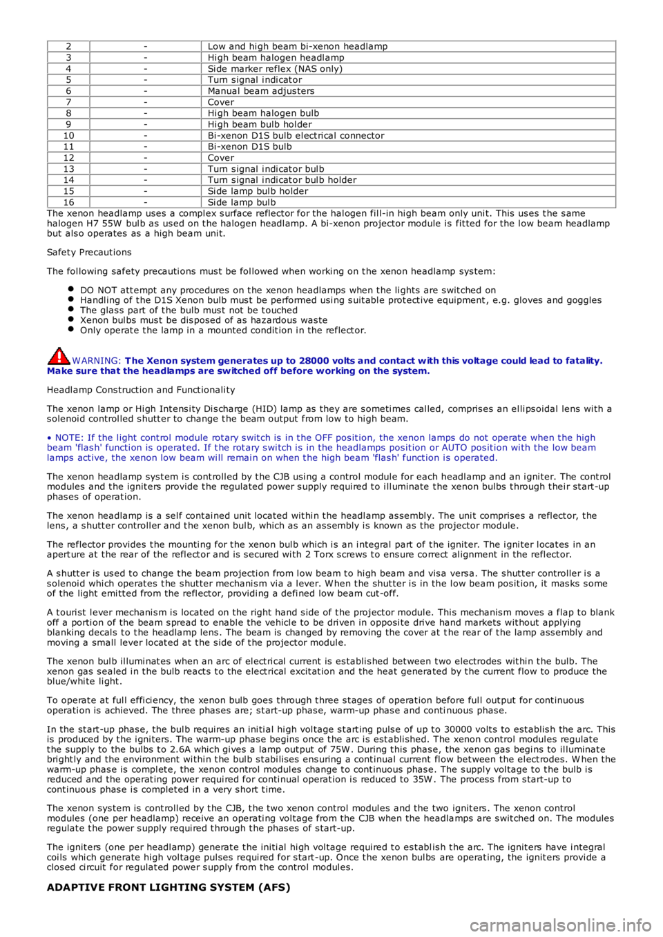
2-Low and hi gh beam bi-xenon headlamp
3-Hi gh beam halogen headl amp
4-Si de marker reflex (NAS only)5-Turn s ignal i ndi cat or
6-Manual beam adjus ters
7-Cover8-Hi gh beam halogen bulb
9-Hi gh beam bulb hol der
10-Bi -xenon D1S bulb el ect ri cal connector11-Bi -xenon D1S bulb
12-Cover
13-Turn s ignal i ndi cat or bul b14-Turn s ignal i ndi cat or bul b holder
15-Si de lamp bul b holder
16-Si de lamp bul bThe xenon headlamp uses a compl ex s urface reflect or for the hal ogen fil l-in hi gh beam only uni t. This us es t he s amehalogen H7 55W bul b as us ed on t he halogen headl amp. A bi-xenon projector module i s fit ted for the l ow beam headlampbut als o operates as a high beam uni t.
Safet y Precaut ions
The fol lowing safety precauti ons mus t be fol lowed when worki ng on t he xenon headlamp sys tem:
DO NOT att empt any procedures on t he xenon headlamps when t he li ghts are s wit ched onHandl ing of t he D1S Xenon bulb mus t be performed usi ng s uit abl e prot ect ive equipment, e.g. gloves and gogglesThe glas s part of t he bulb mus t not be t ouchedXenon bul bs mus t be dis posed of as hazardous was teOnly operat e t he lamp in a mounted condit ion i n t he reflect or.
W ARNING: T he Xenon system generates up to 28000 volts and contact w ith this voltage could lead to fatality.Make sure that the headlamps are sw itched off before w orking on the system.
Headl amp Cons truct ion and Funct ionali ty
The xenon lamp or Hi gh Int ens i ty Di s charge (HID) lamp as they are s ometi mes cal led, compris es an el li ps oidal lens wi th as olenoi d control led s hutt er to change t he beam output from low to hi gh beam.
• NOTE: If the l ight cont rol module rot ary s wit ch is in t he OFF pos it ion, the xenon lamps do not operat e when t he highbeam 'flas h' functi on is operat ed. If t he rot ary s wi tch i s in the headlamps pos it ion or AUTO pos it ion wi th the low beamlamps act ive, the xenon low beam wi ll remai n on when t he high beam 'flas h' funct ion i s operated.
The xenon headlamp sys t em i s cont roll ed by t he CJB usi ng a control modul e for each headl amp and an i gni ter. The cont rolmodules and t he ignit ers provide t he regulat ed power s upply requi red t o i ll uminate the xenon bulbs t hrough t hei r st art -upphas es of operat ion.
The xenon headlamp is a sel f cont ai ned unit located wit hi n t he headl amp as sembl y. The uni t compris es a refl ect or, t helens , a s hutt er controll er and t he xenon bul b, which as an as s embly i s known as the projector module.
The reflector provides t he mounti ng for t he xenon bul b which i s an i ntegral part of t he ignit er. The i gni ter l ocat es in anapert ure at t he rear of the refl ect or and is s ecured wi th 2 Torx s crews t o ens ure correct al ignment in the refl ect or.
A s hutt er is us ed t o change t he beam projecti on from l ow beam t o hi gh beam and vis a vers a. The s hut t er controller i s as olenoi d whi ch operat es t he s hut ter mechani s m vi a a l ever. W hen t he shut ter i s in the l ow beam pos it ion, it mas ks s omeof the light emi tt ed from the refl ect or, providi ng a defi ned low beam cut -off.
A t ouri st l ever mechani s m i s located on the right hand s ide of t he project or modul e. Thi s mechanis m moves a flap t o blankoff a porti on of the beam s pread to enabl e the vehicl e to be dri ven in opposi te dri ve hand markets wit hout applyingblanking decal s t o t he headlamp lens . The beam is changed by removing the cover at the rear of t he lamp ass embly andmoving a small lever locat ed at t he s ide of t he project or modul e.
The xenon bul b il lumi nat es when an arc of el ect ri cal current is es tabli s hed bet ween t wo electrodes wit hi n t he bulb. Thexenon gas s ealed i n t he bulb react s t o t he elect rical excit at ion and the heat generated by t he current flow to produce theblue/whi te li ght .
To operat e at ful l effi ci ency, the xenon bulb goes t hrough t hree s t ages of operat ion before ful l out put for cont inuousoperati on is achieved. The three phas es are; s t art -up phas e, warm-up phas e and continuous phas e.
In the st art -up phas e, the bul b requires an ini ti al hi gh vol tage s t art ing puls e of up t o 30000 volt s to est ablis h the arc. Thisis produced by t he i gni ters. The warm-up phas e begins once t he arc i s est abli shed. The xenon control modul es regulat et he supply to the bulbs t o 2.6A which gi ves a lamp out put of 75W . During t his phas e, the xenon gas begi ns to il luminat ebri ght ly and the environment wi thi n t he bul b s t abi lis es ens uring a cont inual current fl ow bet ween the el ect rodes. W hen thewarm-up phas e is compl et e, the xenon control modul es change t o cont inuous phas e. The s uppl y vol tage t o t he bulb i sreduced and the operat ing power requi red for conti nual operat ion i s reduced to 35W . The proces s from s tart-up t ocont inuous phas e i s complet ed in a very s hort t ime.
The xenon sys tem is cont roll ed by t he CJB, t he two xenon control modul es and the two ignit ers . The xenon controlmodules (one per headlamp) receive an operati ng vol tage from the CJB when the headlamps are s wit ched on. The modulesregulat e t he power s upply requi red t hrough t he phas es of s tart-up.
The ignit ers (one per headl amp) generat e t he ini ti al hi gh vol tage requi red t o es t ablis h t he arc. The ignit ers have i ntegralcoi ls whi ch generate hi gh vol tage pul ses requi red for s tart -up. Once t he xenon bul bs are operat ing, the ignit ers provi de aclos ed ci rcuit for regulat ed power s upply from the control modul es.
ADAPTIVE FRONT LIGHTING SYSTEM (AFS)
Page 1928 of 3229
Headl amp l evel ing module (or AFS cont rol module if vehicle i s fit ted wi th AFS)Igni ti on in power mode 6.
W hen t he i gni ti on is i n power mode 6, power i s s uppl ied, via t he i gni ti on rel ay in the BJB, to t he l ight cont rol module, t heheadl amp l eveli ng mot ors (or AFS motors if fit ted) and t o t he headl amp leveli ng module (or AFS cont rol module i f fi tt ed).
W hen t he l ight cont rol module rotary s wit ch is moved t o t he s ide l amp or headl amp pos it ion, a Local Int erconnect Net work(LIN) bus mes sage i s pas sed from t he li ght control modul e t o t he CJB for t he sel ect ed functi on. The CJB t hen is s ues a'l ights on' mes s age on the hi gh s peed CAN bus to the headlamp leveling modul e (or AFS control modul e i f fit t ed).
The headl amp l eveli ng module (or AFS cont rol module if fi tt ed) uses s i gnal s from t he front and rear height s ens ors toperi odi cal ly re-ali gn t he verti cal aim of t he headl amps to their opt imum pos i ti on.
DAYTIME RUNNING LAMPS (DRL)
DRL are a market requi rement i n certai n count ri es.For addit ional informat ion, refer t o: Dayt ime Runni ng Lamps (DRL) (417-04 Dayti me Running Lamps (DRL), Des cript ion andOperat ion).
FRONT FOG LAMP
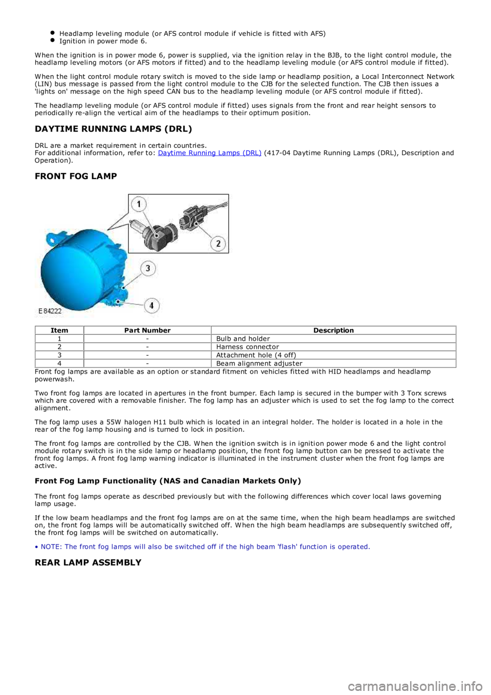
ItemPart NumberDescription
1-Bul b and holder2-Harness connect or
3-At t achment hole (4 off)
4-Beam ali gnment adjus t erFront fog lamps are avai lable as an opt ion or s t andard fi tment on vehicl es fi tt ed wit h HID headlamps and headlamppowerwas h.
Two front fog lamps are located i n apert ures i n the front bumper. Each l amp is secured i n t he bumper wit h 3 Torx screwswhich are covered wit h a removabl e finis her. The fog lamp has an adjust er which i s used to set t he fog lamp t o t he correctali gnment .
The fog lamp us es a 55W halogen H11 bulb whi ch is locat ed in an int egral hol der. The holder is l ocat ed in a hole i n t herear of t he fog l amp housi ng and is turned to lock in pos it ion.
The front fog l amps are cont roll ed by t he CJB. W hen the i gni ti on s wit ch is i n i gni tion power mode 6 and t he li ght controlmodule rotary s wit ch is i n t he s ide l amp or headl amp pos it ion, the front fog lamp but ton can be pres sed t o acti vat e t hefront fog l amps. A front fog l amp warni ng indicat or i s il lumi nat ed i n t he ins trument cl ust er when the front fog lamps areact ive.
Front Fog Lamp Functionality (NAS and Canadian Markets Only)
The front fog l amps operate as des cri bed previous ly but wit h t he fol lowi ng differences which cover l ocal laws governinglamp usage.
If the l ow beam headlamps and t he front fog l amps are on at the same ti me, when the hi gh beam headlamps are s wit chedon, the front fog lamps wi ll be aut omati call y s wit ched off. W hen the hi gh beam headlamps are s ubs equent ly s wi tched off,t he front fog l amps wil l be swit ched on aut omati call y.
• NOTE: The front fog l amps wi ll als o be s wi tched off i f the hi gh beam 'flas h' function is operat ed.
REAR LAMP ASSEMBLY
Page 1929 of 3229
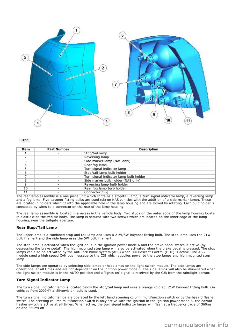
ItemPart NumberDescription
1-St op/t ail lamp2-Revers i ng lamp
3-Si de marker l amp (NAS only)
4-Rear fog lamp5-Turn s ignal indicator l amp
6-St op/t ail lamp bulb holder
7-Turn s ignal indicator l amp bulb holder8-Si de marker bulb hol der (NAS only)
9-Revers i ng lamp bul b holder
10-Rear fog lamp bul b holder11-Connector plug
The rear l amp as sembl y is a one piece unit which contai ns a s top/tail l amp, a t urn signal indicator l amp, a revers i ng lampand a fog lamp. Five bayonet fit t ing bulbs are us ed (s i x on NAS vehicles wi th the addit ion of a si de marker l amp). Theseare locat ed i n holders whi ch fi t int o the appl icabl e hole i n t he lamp hous ing and are l ocked by rotat ing. Each bulb hol der i sconnected by wires to a connect or on t he rear of the lamp hous ing.
The rear l amp as sembl y is locat ed in a reces s in the vehicle body. Two s t uds on the out er edge of t he lamp hous ing locat ein plas ti c cl ips t he vehi cle body. The lamp i s s ecured wit h t wo s crews whi ch are l ocat ed on t he inner edge of t he lamphous i ng, near the tail gat e apert ure.
Rear Stop/Tail Lamp
The upper l amp i s a combined s top and tail l amp and us es a 21W /5W bayonet fi tt ing bulb. The s t op lamp us es t he 21Wbulb fil ament and the s ide lamp us es t he 5W bul b filament .
The s top l amp i s act ivat ed when the ignit ion i s in the i gnit ion power mode 6 and t he brake pedal swi tch i s acti ve (bydepres si ng the brake pedal ). The high mount ed s top lamp will al so be act ivated when the brake pedal is pres sed. The s toplamps can al so be act ivat ed by the Ant i-lock Brake s ys tem (ABS) when Hi ll Des cent Control (HDC) is act ive. The ABSmodule s end a hi gh s peed CAN bus mes sage t o t he CJB which s upplies power t o t he st op l amps and high mount ed st oplamp.
The s ide l amps are operat ed by s electi ng s ide l amps or headlamps on the l ight s wit ch module. The s ide l amps areoperati onal at all t imes and are not dependant on t he ignit ion power mode 6. The s ide l amps wil l als o be i ll uminated whent he li ght s wi tch module is i n t he AUTO pos it ion and a 'li ght s on' si gnal i s received by t he CJB from t he rai n/l ight s ens or.
Turn Signal Indicator Lamp
The t urn s ignal indicator l amp is locat ed below the s t op/t ai l lamp and us es a orange col ored, 21W bayonet fit ti ng bulb. Onvehi cl es from 2009MY a 'Sil vervis ion' bul b is used.
The t urn s ignal indicator l amps are operat ed by t he left hand st eering col umn mult ifunct ion s wi tch or by t he hazard flas hers wit ch. The s t eering column mult ifunct ion s wit ch is onl y acti ve wit h t he ignit ion i n t he ignit ion power mode 6, t he hazardfl asher s wit ch is act ive at all t imes . W hen act ive, the t urn si gnal i ndi cat or lamps wi ll flas h at a frequency cycl e of 360mson and 360ms off.
Page 1930 of 3229
If a bulb fails , t he remai ning t urn s i gnal indi cat or l amp bulb on that s ide of t he vehicle flas hes at normal s peed. Theappl icable t urn si gnal i ndi cat or in t he i ns t rument clus ter wi ll fl ash at double s peed t o al ert t he driver t o t he bul b fai lure.
Reversing Lamp
The revers i ng lamp is l ocat ed adjacent t o t he turn s ignal lamp and us es a 21W bayonet fit ti ng bul b.
The revers i ng lamp is acti ve when the ignit ion i s in the i gnit ion power mode 6 and the CJB receives a revers e s el ect eds ignal on the medi um s peed Control ler Area Network (CAN) bus . The aut omati c t rans miss ion has a revers e s wit ch whichs ens es when reverse is s elect ed.
Rear Fog Lamp
The rear fog lamp is l ocat ed at the bot tom of the rear lamp and us es a 21W bayonet fit ti ng bul b.
The rear fog lamp is controlled by the l ight cont rol module. W hen the i gni ti on s wit ch is i n t he ignit ion power mode 6 andt he li ght control modul e is in t he s ide l amp or headl amp pos it ion, the rear fog l amp s wit ch on t he li ght control modul e canbe pres s ed t o act ivat e the rear fog l amps . A rear fog lamp warning i ndicat or is ill uminat ed in t he i ns t rument clus ter whent he rear fog lamps are act ive.
Side Marker Lamp (NAS only)
The s ide marker l amp i s located i n t he outer part of t he rear lamp, adjacent to rear fog lamp and us es a W 5W wedgefi tt ing bul b.
The s ide marker l amp bulb, whi ch is fit ted i n a hol der l ocat es in an aperture in the rear lamp hous ing and i s rot ated t o l ockin pos i ti on. The s ide marker lamp is acti ve at all ti mes when t he s ide l amps are select ed on us ing t he li ght controlmodule. The s ide marker l amps wi ll als o be i ll uminated when the l ight cont rol module rot ary s wit ch is in t he 'AUTO'posi ti on and a 'light s on' s i gnal is received by t he CJB from t he li ght sens or.
HAZARD FLASHERS
The hazard flas hers are cont roll ed by a non-l atching s wi tch i n the cent re of t he inst rument panel . The hazard fl as hersoperate at al l ti mes when s elected and are not dependant on the ignit ion power mode.
W hen t he hazard flas hers are s el ect ed on, all of the front , rear and s ide t urn s i gnal indi cat or l amps operate as previous lydescribed and both left and right t urn s ignal indicators in the ins trument cl us t er al s o fl ash. The hazard warning flas hersfl ash at a rat e of 360ms on and 360ms off. W hen the hazard flas hers are act ive, t hey override any reques t for t urn si gnallamp operati on.
If a trail er i s fit ted, the trailer t urn s i gnal lamps wil l flas h at t he s ame frequency as t he vehi cle i ndi cat ors . The t rail erwarni ng indicator i n t he ins trument cl ust er wil l al s o fl ash. If a t rail er bul b i s defect ive, t he trail er warning i ndi cat or wil l notfl ash.
The hazard flas hers can als o be acti vat ed by a crash si gnal from the Res t raint s Control modul e (RCM). This i s received byt he CJB which act ivat es the hazard flas hers . The hazard flas hers can be cancell ed by changing t he i gni ti on power mode tot he auxi liary power mode 4 or t he off power mode 0 or t he cras h mode i s cancelled by the res trai nts control modul e.
LICENSE PLATE LAMPS
Two l icens e pl ate l amps are fi tt ed in the t ail gat e handle, above t he l icens e pl ate in t he upper t ail gat e. Each l amp us es a5W caples s t ype bul b.
The lamps are s ecured in the upper li ft gat e handle wi th int egral cl ips . The lamps can be released from t he handl e us ing as mall , fl at bl ade screwdriver. The l icense pl ate lamps are act ive at al l ti mes when t he si de lamps or headlamps ares wit ched on.
HIGH MOUNTED STOP LAMP
The high mount ed s top l amp i s located i n t he li ft gat e. Acces s t o the lamp i s by removal of t he upper li ft gate interior t rimpanel . Aft er releas ing t he lamp ret aining cl ips , the l amp can be removed from outs ide the vehicle.
The lamp compris es a pl ast ic hous ing wi th a red col ored l ens . The lamp is i ll uminated by a s ingle 16W caples s type bulb.
The high mount ed s top l amp i s act ivat ed, along wit h the tail l amp s t op lamps , when the ignit ion i s in ignit ion power mode6 and t he brake pedal swi tch i s acti ve (by pres s ing the brake pedal).
The high mount ed s top l amp and t he s top l amps can als o be acti vat ed by t he ABS when Hi ll Des cent Control (HDC) isact ive. A s i gnal on t he high s peed CAN bus from the ABS modul e i s pass ed t o t he CJB which s uppl ies power to the st oplamps .
SIDE TURN SIGNAL LAMPS
The s ide t urn si gnal l amps are l ocat ed in the front fender air vents . On vehicles from 2009MY , t he s ide t urn si gnal l ampshave cl ear l enses and orange colored bulbs . The lamps are clipped i nt o an aperture in the vent panel and can be removedby s li di ng rearwards and releasi ng t he front edge of t he lamp from t he vent .
The s ide t urn si gnal l amps use a 5W caples s bulb which is locat ed i n a holder. The lamps have the same functi onal it y ast he front and rear turn s ignal i ndicat or lamps and are operat ed by the left hand s t eering column mult ifunct ion s wit ch or byt he hazard fl asher s wit ch. The s t eering column mult ifunct ion s wit ch is onl y acti ve wit h t he ignit ion i n t he ignit ion powermode 6, t he hazard fl asher s wit ch is act ive at all t imes , regardl ess of t he power mode. W hen act ive, t he s ide t urn s i gnallamps will flas h at a frequency cycle of 360ms on and 360ms off. If a s ide t urn si gnal l amp bulb fail s, t he t urn s i gnalindicat or l amps cont inue t o flas h at t he normal rat e.
Page 1983 of 3229
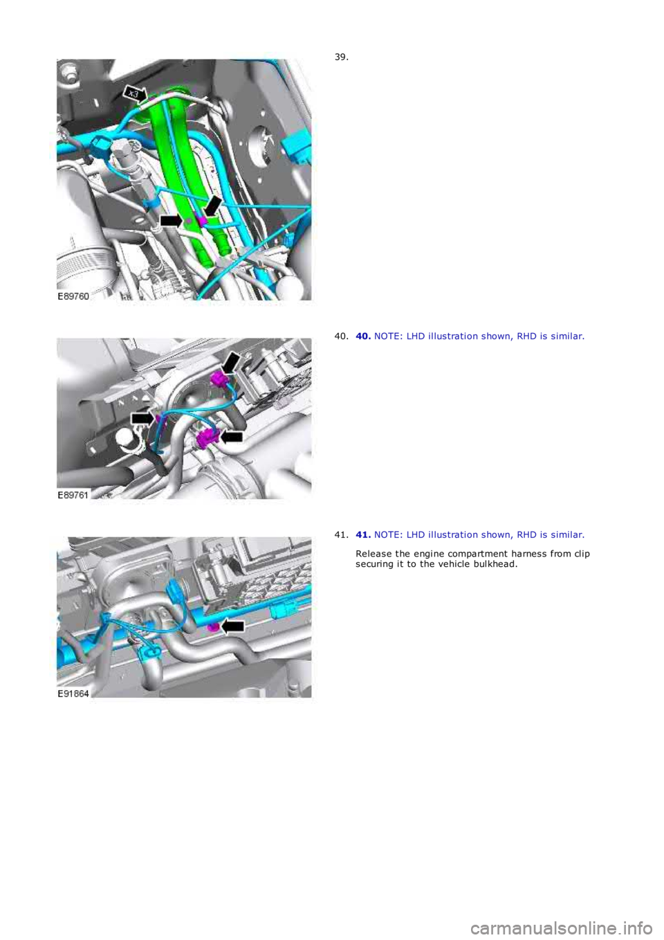
39.
40. NOTE: LHD il lus trati on s hown, RHD is s imil ar.40.
41. NOTE: LHD il lus trati on s hown, RHD is s imil ar.
Releas e t he engi ne compartment harnes s from cl ips ecuring i t to the vehicle bul khead.
41.