2006 LAND ROVER FRELANDER 2 ECU
[x] Cancel search: ECUPage 2119 of 3229
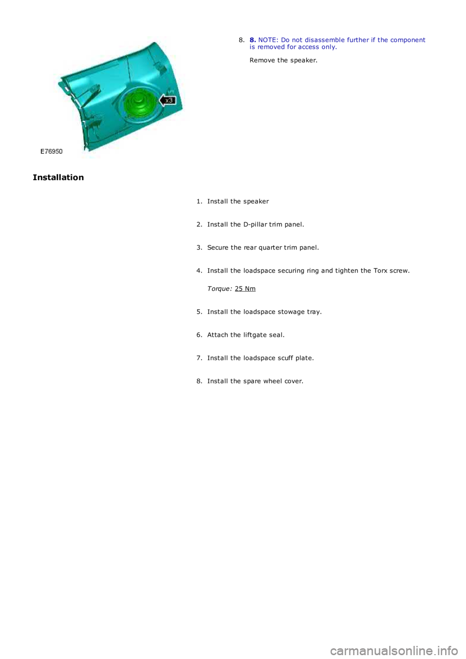
8.
NOTE: Do not dis ass embl e further if t he component
i s removed for acces s onl y.
Remove t he s peaker.
8.
Installation Inst all t he s peaker
1.
Inst all t he D-pi llar t ri m panel.
2.
Secure t he rear quart er t rim panel.
3.
Inst all t he loadspace s ecuring ring and t ight en the Torx s crew.
T orque: 25 Nm 4.
Inst all t he loadspace s towage t ray.
5.
At tach t he li ft gat e s eal.
6.
Inst all t he loadspace s cuff plat e.
7.
Inst all t he s pare wheel cover.
8.
Page 2127 of 3229
Publi s hed: 11-May-2011
Interior Trim and Ornamentation - HeadlinerVehicles Without: Tilting Roof
Opening Panel
Removal and Inst all ati on
Removal
CAUTION: Make s ure that the wiring harnes s es are correct ly locat ed.
• NOTE: If a headl iner is t o be replaced, i t is i mperat ive t hat the was her hos e and wi ri ng harnes s are i nst all ed to theirori ginal pos it ions . Fai lure to fol low t hese ins truct ions may impede t he s ide air curt ain modul e performance.
• NOTE: Note the pos it ion of t he wi ri ng harness es t o aid ins tall ati on.
Remove both A-pil lar t ri m panels .
Refer t o: A-Pil lar Tri m Panel (501-05 Int erior Trim andOrnament ati on, Removal and Ins tal lat ion).
1.
Remove both B-pil lar upper t ri m panels .
Refer t o: B-Pil lar Upper Trim Panel (501-05 Interior Tri m andOrnament ati on, Removal and Ins tal lat ion).
2.
Remove both C-pil lar t ri m panels .
Refer t o: C-Pil lar Tri m Panel (501-05 Int erior Trim andOrnament ati on, Removal and Ins tal lat ion).
3.
Remove both D-pil lar upper t rim panels .
Refer t o: D-Pi llar Trim Panel (501-05 Int eri or Trim andOrnament ati on, Removal and Ins tal lat ion).
4.
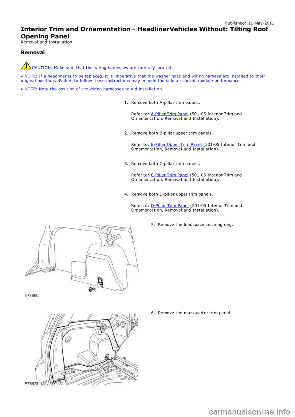
Remove t he loadspace s ecuring ring.5.
Remove t he rear quart er t ri m panel.6.
Page 2134 of 3229
Inst all t he ti re pres sure monit ori ng s ys t em receiver.
3.
4. NOTE: Thi s s tep requires the ai d of anot her techni ci an.
Inst all t he headl iner.
4.
Connect t he was her jet hos e.
5.
At tach t he front door s eal s .
6.
At tach t he rear of the headli ner.
7.
Reposi ti on the rear s eat s .
8.
Reposi ti on the front s eats .
9.
Inst all t he pas s enger as s is t handl es .
10.
Inst all t he s un vi s ors .
11.
Inst all t he rear int eri or l amp.
12.
Inst all t he overhead cons ol e.
Refer t o: Overhead Cons ole (501-12 Ins trument Panel and Cons ole,
Removal and Ins tall ati on).
13.
Inst all t he int erior rear vi ew mi rror.
Refer t o: Int erior Rear View Mirror (501-09 Rear Vi ew Mi rrors ,
Removal and Ins tall ati on).
14.
Connect t he headl iner wiring harnes s and s ecure t he cl ips .
15.
Inst all t he s peaker gril le.
16.
Inst all t he cowl s ide trim panel .
Refer t o: Cowl Si de Tri m Panel (501-05 Interior Tri m and
Ornament ati on, Removal and Ins tal lat ion).
17.
Inst all t he glove compartment .
Refer t o: Glove Compart ment (501-12 Ins trument Panel and
Consol e, Removal and Ins t al lat ion).
18.
Inst all t he rear quart er t ri m panel.
19.
Inst all t he loadspace s ecuring ring and t ight en the Torx s crew.
T orque: 25 Nm 20.
Inst all t he D-pi llar t ri m panels .
Refer t o: D-Pi llar Trim Panel (501-05 Int eri or Trim and
Ornament ati on, Removal and Ins tal lat ion).
21.
Page 2136 of 3229
Publi s hed: 11-May-2011
Interior Trim and Ornamentation - HeadlinerVehicles With: Tilting Roof
Opening Panel
Removal and Inst all ati on
Removal CAUTION: Make s ure that the wiring harnes s es are correct ly locat ed.
• NOTE: If a headl iner is t o be replaced, i t is i mperat ive t hat the was her hos e and wi ri ng harnes s are i nst all ed to their
ori ginal pos it ions . Fai lure to fol low t hese ins truct ions may impede t he s ide air cur t ain modul e performance.
• NOTE: Note the pos it ion of t he wi ri ng harness es t o aid ins tall ati on.
Remove both A-pil lar t ri m panels .
Refer t o: A-Pil lar Tri m Panel (501-05 Int erior Trim and
Ornament ati on, Removal and Ins tal lat ion).
1.
Remove both B-pil lar upper t ri m panels .
Refer t o: B-Pil lar Upper Trim Panel (501-05 Interior Tri m and
Ornament ati on, Removal and Ins tal lat ion).
2.
Remove both C-pil lar t ri m panels .
Refer t o: C-Pil lar Tri m Panel (501-05 Int erior Trim and
Ornament ati on, Removal and Ins tal lat ion).
3.
Remove both D-pil lar upper t rim panels .
Refer t o: D-Pi llar Trim Panel (501-05 Int eri or Trim and
Ornament ati on, Removal and Ins tal lat ion).
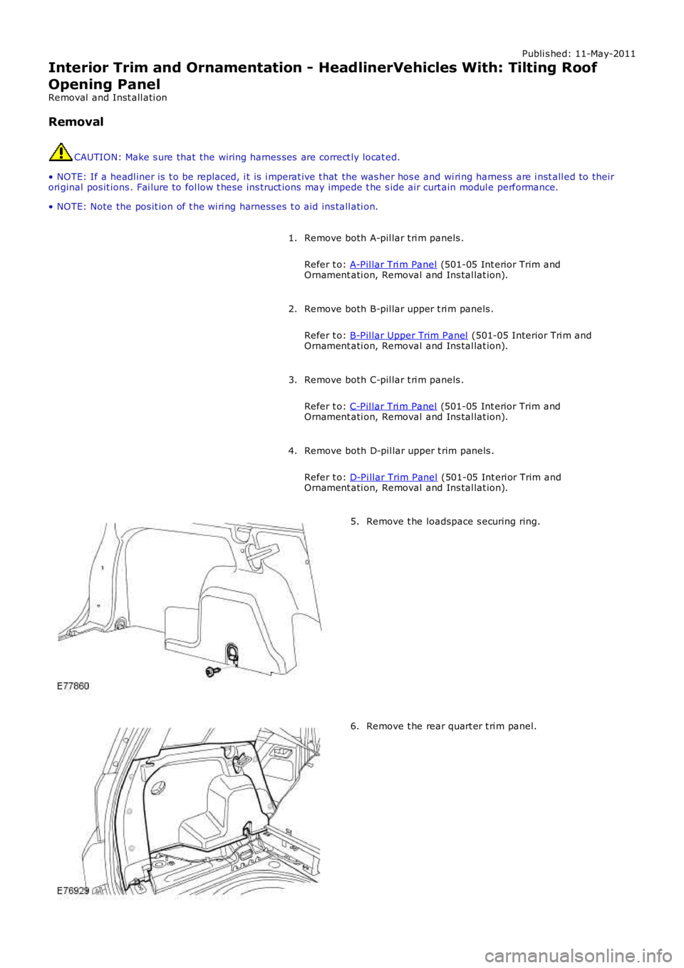
4. Remove t he loadspace s ecuring ring.
5. Remove t he rear quart er t ri m panel.
6.
Page 2145 of 3229
Connect t he headl iner wiring harnes s and s ecure t he cl ips .
19.
Inst all t he s peaker gril le.
20.
Inst all t he cowl s ide trim panel .
Refer t o: Cowl Si de Tri m Panel (501-05 Interior Tri m and
Ornament ati on, Removal and Ins tal lat ion).
21.
Inst all t he glove compartment .
Refer t o: Glove Compart ment (501-12 Ins trument Panel and
Consol e, Removal and Ins t al lat ion).
22.
Inst all t he rear quart er t ri m panel.
23.
Inst all t he loadspace s ecuring ring and t ight en the Torx s crew.
T orque: 25 Nm 24.
Inst all t he D-pi llar t ri m panels .
Refer t o: D-Pi llar Trim Panel (501-05 Int eri or Trim and
Ornament ati on, Removal and Ins tal lat ion).
25.
Inst all t he C-pi llar t ri m panels .
Refer t o: C-Pil lar Tri m Panel (501-05 Int erior Trim and
Ornament ati on, Removal and Ins tal lat ion).
26.
Inst all t he B-pi llar t ri m panels .
Refer t o: B-Pil lar Upper Trim Panel (501-05 Interior Tri m and
Ornament ati on, Removal and Ins tal lat ion).
27.
Inst all t he A-pi llar t ri m panels .
Refer t o: A-Pil lar Tri m Panel (501-05 Int erior Trim and
Ornament ati on, Removal and Ins tal lat ion).
28.
Page 2155 of 3229
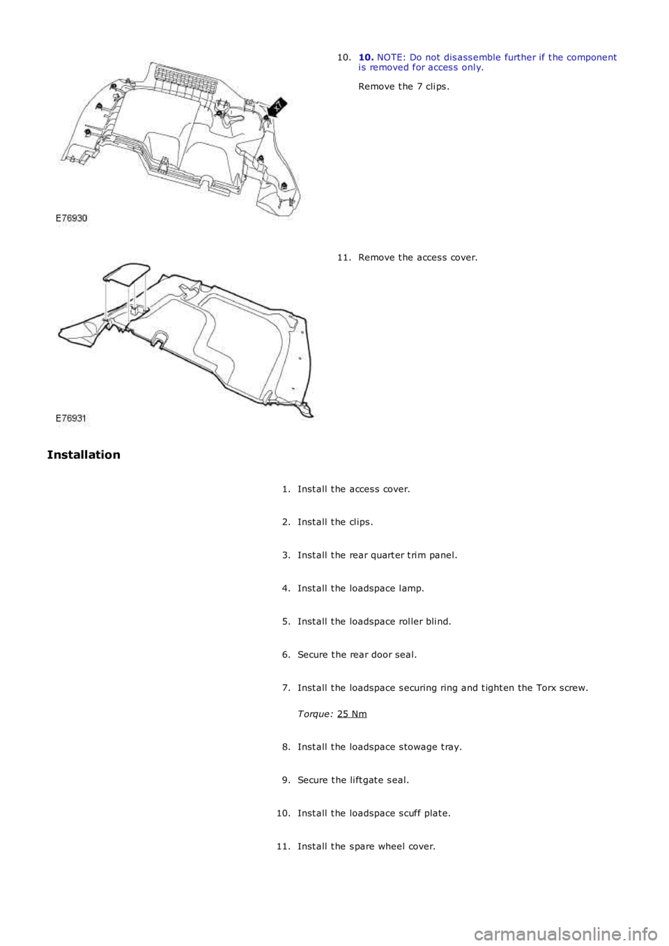
10.
NOTE: Do not dis ass emble further if t he component
i s removed for acces s onl y.
Remove t he 7 cli ps .
10. Remove t he acces s cover.
11.
Installation Inst all t he acces s cover.
1.
Inst all t he cl ips .
2.
Inst all t he rear quart er t ri m panel.
3.
Inst all t he loadspace l amp.
4.
Inst all t he loadspace rol ler bli nd.
5.
Secure t he rear door seal.
6.
Inst all t he loadspace s ecuring ring and t ight en the Torx s crew.
T orque: 25 Nm 7.
Inst all t he loadspace s towage t ray.
8.
Secure t he li ft gat e s eal.
9.
Inst all t he loadspace s cuff plat e.
10.
Inst all t he s pare wheel cover.
11.
Page 2166 of 3229
Publi s hed: 11-May-2011
Rear View Mirrors - Rear View Mirrors
Diagnosi s and Tes ti ng
Principles of Operation
For a detail ed descripti on of the rear vi ew mirror s ys t ems, refer t o t he rel evant Descripti on and Operat ion s ecti on in t heworks hop manual .REFER to: Rear View Mirrors (501-09 Rear View Mirrors, Des cri pt ion and Operati on).
Inspection and Verification
CAUTION: Di agnos is by s ubs ti tut ion from a donor vehicle is NO T acceptabl e. Subs ti tut ion of cont rol modules doesnot guarant ee confirmat ion of a faul t, and may als o caus e addit ional fault s i n t he vehi cl e being t est ed and/or t he donorvehi cl e.
1. Verify t he cus t omer concern.1.
2. Vis ually ins pect for obvious s igns of mechani cal or electrical damage.2.
Visual InspectionMechanicalElectrical
Condit ion, correct ins tal lati on and s ecurit y of rear view mirrorsFus es/rel ays (refer to elect rical guide)W iring harnes sCorrect engagement of el ect ri cal connect orsLoos e or corroded connecti ons
3. If an obvious cause for an obs erved or report ed concern is found, correct t he caus e (if pos s ible) beforeproceeding t o t he next s t ep.3.
4. If t he caus e is not vis ually evi dent , check for Di agnos ti c Trouble Codes (DTCs) and refer t o t he DTC Index.4.
DTC Index
• NOTE: If the control modul e or a component i s s us pect and the vehicle remains under manufacturer warrant y, refer t o theW arranty Pol icy and Procedures manual (s ect ion B1.2), or determine i f any pri or approval programme is in operat ion, pri ort o the ins tall ati on of a new module/component.
• NOTE: Generic scan t ool s may not read the codes li st ed, or may read only fi ve digit codes . Mat ch the five di git s from t hes can tool to the firs t fi ve di git s of the seven digi t code l is ted to ident ify t he faul t (t he las t t wo digi ts gi ve ext rainformat ion read by the manufact urer-approved diagnost ic s ys tem).
• NOTE: W hen performing volt age or res is t ance t est s , always use a digi tal mult imeter (DMM) accurat e t o t hree deci malplaces and wit h a current cal ibrat ion cert ificate. W hen tes ti ng res i st ance, always take the res is tance of the DMM l eads i ntoaccount.
• NOTE: Check and recti fy bas ic faul ts before beginni ng diagnos t ic rout ines i nvol vi ng pinpoint t es t s.
• NOTE: If DTCs are recorded and, aft er performi ng the pi npoi nt tes ts , a fault is not present , an int ermi tt ent concern maybe t he caus e. Always check for loose connect ions and corroded terminals .
DT CDescriptionPossible CausesActionB116311Left Mirror Heat er Outputs hort t o groundShort t o groundRefer t o t he electrical ci rcuit diagrams and tes t l eft mi rrorheater output circui t for s hort t o ground
B116315Left Mirror Heat er Outputs hort t o powerShort t o poweror open circuitRefer t o t he electrical ci rcuit diagrams and tes t l eft mi rrorheater output circui t for s hort t o power or open circui t
B116411Ri ght Mi rror Heat er Outputs hort t o groundShort t o groundRefer t o t he electrical ci rcuit diagrams and tes t right mirrorheater output circui t for s hort t o groundB116415Ri ght Mi rror Heat er Outputs hort t o powerShort t o poweror open circuitRefer t o t he electrical ci rcuit diagrams and tes t right mirrorheater output circui t for s hort t o power or open circui t
B1A9411Driver MirrorShort t o groundRefer t o t he electrical ci rcuit diagrams and tes t dri ver mirrorfol d mot or ci rcuit for short to ground
B1A9415Driver MirrorShort t o poweror open circuitRefer t o t he electrical ci rcuit diagrams and tes t dri ver mirrorfol d mot or ci rcuit for short to power or open ci rcuit
B1A9511Pas senger MirrorShort t o groundRefer t o t he electrical ci rcuit diagrams and tes t pas sengermi rror fold motor circui t for s hort t o ground
B1A9515Pas senger MirrorShort t o poweror open circuitRefer t o t he electrical ci rcuit diagrams and tes t pas sengermi rror fold motor circui t for s hort t o power or open circui t
B1C0911Driver Left/Right Mi rrorMot or CircuitShort t o groundRefer t o t he electrical ci rcuit diagrams and tes t dri verl eft/right mirror mot or ci rcuit for short to groundB1C0915Driver Left/Right Mi rrorMot or CircuitShort t o poweror open circuitRefer t o t he electrical ci rcuit diagrams and tes t dri verl eft/right mirror mot or ci rcuit for short to power or open ci rcuit
B1C1011Driver Up/Down MirrorMot or CircuitShort t o groundRefer t o t he electrical ci rcuit diagrams and tes t dri verup/down mirror mot or ci rcuit for s hort t o ground
Page 2181 of 3229
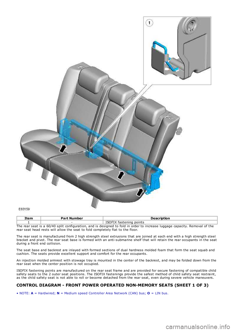
Item
Part Number Description
1 -ISOFIX fast ening point s
The rear s eat is a 60/40 s plit confi gurati on, and i s des igned to fold in order to i n crease luggage capaci ty. Removal of t he
rear s eat head res ts wi ll all ow t he s eat to fold compl et ely flat t o t he fl oor.
The rear s eat is manufact ured from 2 high s t rength st eel ext rus ions t hat are joined at each end wit h a hi gh st rengt h s teel
bracket and pi vot . The rear s eat bas e i s formed wi th an ant i-s ubmarine shelf t hat wi l l ret ai n t he rear occupants i n t he s eat
duri ng a front end col li si on.
The s eat bas e and backrest are i nl ayed wit h formed s ect ions of dual hardnes s mol ded foam that form the s eat s quab and
cus hion. The s eats provi de excell ent support and comfort for t he rear occupants .
An i nject ion molded armres t wit h s t owage tray is mount ed in the center of t he backre s t, and may be fol ded down from t he
rear s eat when the center pos it ion i s not occupi ed.
ISOFIX fast ening point s are manufact ured on the rear s eat frame and are provided for secure fas tening of compati ble chil d
s afety seat s t o the 2 outer s eat pos it ions . The ISOFIX fas t eni ngs provide t he s afes t method of chil d s afety seat res t rai nt ,
as t he chi ld s afet y s eat is not able to roll or become det ached from t he rear s eat , even during s evere vehicle maneuvers .
CONTROL DIAGRAM - FRONT POWER OPERATED NON-MEMORY SEATS (SHEET 1 OF 3)
• NOTE: A = Hardwi red; N = Medium s peed Cont roll er Area Net work (CAN) bus; O = LIN bus .