2006 LAND ROVER FRELANDER 2 ECU
[x] Cancel search: ECUPage 2278 of 3229
Remove t he cool ant hos e clamps .
5.
Connect t he A/C pipes t o the TXV and ti ght en t he M6 nut .
T orque: 10 Nm 6.
Inst all t he ECM bracket as s embly and ti ght en t he nut s .
T orque: 10 Nm 7.
Connect t he ECM elect rical connectors .
8.
9. W ARNING: Make sure t hat a new bolt i s ins tal led.
Connect t he s teeri ng col umn l ower s haft and t ight en the bol t.
T orque: 25 Nm 9.
Connect t he drain tube t o t he heater hous i ng.
10.
Secure t he redundant el ect ri c boos t er heater el ect ri cal connector.
11.
Inst all t he cent er, lower ducts t o t he heater hous i ng.
12.
Inst all t he NVH pad.
13.
Inst all t he ins trument panel wiring harnes s .
14.
Inst all t he auxi liary juncti on box acces s cover.
15.
Secure t he ins trument panel harnes s to the trans mi ss i on tunnel.
16.
Secure and t ighten the eart h l ead.
T orque: 10 Nm 17.
Connect t he body harnes s t o t he i ns t rument panel .
18.
Inst all t he fl oor consol e extens ions.
19.
Inst all t he s el ect or lever mount ing bracket.
20.
Inst all t he transmis si on s elector lever.
Refer t o: Sel ect or Lever As sembl y (307-05 Aut omat ic
Trans mi ss ion/Transaxle Ext ernal Cont rol s , Removal and
Inst all at ion).
21.
Inst all t he LH front s eat .
Refer t o: Front Seat (501-10 Seati ng, Removal and Ins tal lati on).
22.
Inst all both cowl s ide t rim panels .
Refer t o: Cowl Si de Tri m Panel (501-05 Interior Tri m and
Ornament ati on, Removal and Ins tal lat ion).
23.
Secure both scuff pl ate t rim panels .
24.
Inst all t he A-pi llar center t rim panels .
25.
Page 2292 of 3229
Inst all t he cl ips .
1.
Inst all t he regis t er ducti ng.
2.
Inst all t he winds hield defros ter duct.
3.
Inst all t he pas s enger s ide regis t er.
4.
Inst all t he dri ver s ide regis ter.
5.
Inst all t he dri ver s ide i nst rument panel end trim panel .
6.
Inst all t he keyl es s s t art cont rol module.
7.
Inst all t he keyl es s s t art cont rol module trim cover.
8.
Inst all t he in-vehicl e temperature s ens or.
9.
Inst all t he winds hield defros ter t ri m panel.
10.
Inst all t he glove compartment s upport panel s .
11.
Inst all t he glove compartment l id hi nges .
12.
Inst all t he glove compartment l amp.
13.
Inst all t he pas s enger ai r bag modul e.
T orque: 10 Nm 14.
Inst all t he glove compartment s t ri ker reinforcement panel.
15.
W it h ass i st ance, i ns t all the ins trument panel upper s ect ion.
16.
Secure t he wiring harnes s cli p t o t he pas s enger s ide of t he
i ns t rument panel upper secti on.
17.
Secure t he 2 wi ri ng harness cl ips t o t he winds hield defros ter duct
and connect the sunload s ens or.
18.
W it h ass i st ance, s ecure t he ins trument panel upper s ecti on.
19.
Inst all t he winds hield defros ter outer finis hers .
20.
Connect t he pass enger ai r bag modul e electrical connect ors .
21.
Connect t he glove compart ment lamp el ect ri cal connector.
22.
Secure t he pass enger ai r bag modul e and glove compart ment lamp
wi ri ng harness .
23.
Inst all t he glove compartment .
24.
Page 2293 of 3229
Refer t o: Glove Compart ment (501-12 Ins trument Panel andConsol e, Removal and Ins t al lat ion).
Inst all t he pas s enger s ide ins trument panel end trim panel .25.
Secure t he wiring harnes s s upport bracket .26.
Secure t he wiring harnes s t o t he cent er of the i nst rument panelupper s ecti on.27.
Inst all t he cl imat e control as s embly.28.
Inst all t he audi o unit .29.
Inst all t he cent er speaker.30.
Inst all t he video dis play.
Refer t o: Video Dis play (415-01 Informati on and Entert ainmentSyst em, Removal and Ins tall ati on).
31.
Inst all t he fl oor consol e.
Refer t o: Fl oor Cons ole (501-12 Inst rument Panel and Cons ole,Removal and Ins tall ati on).
32.
Inst all t he fl oor consol e extens ions.33.
Inst all both ins trument panel s peakers .34.
Inst all both upper t rim panels .35.
Connect t he in-vehi cl e t emperature s ens or electrical connect or.36.
Connect t he keyl es s s t art module elect rical connect or.37.
Secure t he ins trument cl ust er wiring harnes s cli p.38.
Inst all t he ins trument cl ust er.
Refer t o: Ins trument Clus ter (413-01 Ins t rument Clus t er, Removaland Inst all at ion).
39.
Inst all t he cl ocks pri ng.
Refer t o: Clocks pri ng (501-20B Supplement al Res t raint Sys tem,Removal and Ins tall ati on).
40.
Inst all both cowl s ide t rim panels .
Refer t o: Cowl Si de Tri m Panel (501-05 Interior Tri m andOrnament ati on, Removal and Ins tal lat ion).
41.
Secure both scuff pl ate t rim panels .42.
Inst all t he A-pi llar center t rim panels .43.
Page 2300 of 3229
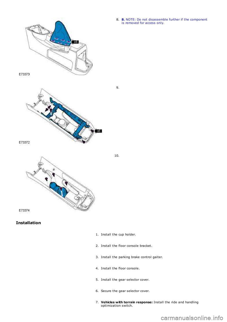
8. NOTE: Do not dis ass embl e further if t he componenti s removed for acces s onl y.8.
9.
10.
Installation
Inst all t he cup hol der.1.
Inst all t he fl oor consol e bracket .2.
Inst all t he parking brake control gai ter.3.
Inst all t he fl oor consol e.4.
Inst all t he gear s elector cover.5.
Secure t he gear s elector cover.6.
Vehicles w ith terrain response: Inst all t he ri de and handl ingopti mizat ion s wit ch.7.
Page 2308 of 3229
OVERVIEW
Al l the vehi cle hinged panels are secured by lat ches with mating st rikers. The lat ches incorporat e panel ajar s wi tches t hatwi ll i nform the dri ver of an open acces s point .
The central locking s ys tem is operat ed by eit her t he remot e handset, front door central locking but tons or t he inst rumentpanel central locki ng s wi tches . The central locking s ys tem cont rols the automatic locking and unlocki ng of t he vehicl e ent rypoints. The soft ware used to cont rol t he cent ral l ocking syst em is i ncorporat ed within t he CJB.
The central locking s ys tem is al so integrat ed with t he interior l ighti ng functi on. The i nt eri or light s and exterior mirror lampsare i lluminated via t he RF recei ver and CJB following a val id unlock reques t from the remote hands et .For addit ional informat ion, refer t o: Interior Light ing (417-02 Interior Lighting, Des cri pt ion and Operation).
If configured by the deal er, the exterior door mirror power fold function is al so operat ed by the central locki ng s yst em.
A concealed mechanical door lock is provided in t he front LH door exteri or handle, and i s used to gain acces s to the vehicle ifthe battery is discharged or t he central l ocking syst em fail s.
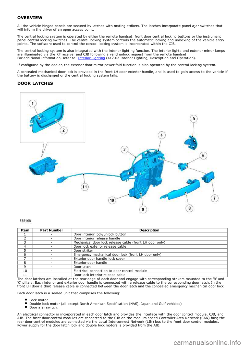
DOOR LATCHES
ItemPart NumberDescription1-Door interior l ock/unlock butt on2-Door interior rel ease handle3-Mechanical door lock releas e cable (front LH door only)4-Door lock exteri or release cable5-Door st riker6-Emergency mechanical door lock (front LH door only)7-Exterior door handle lock cover8-Exterior door handle9-Door latch10-Elect rical connecti on to door control modul e11-Door lock interior rel ease cableThe door latches are inst al led at t he rear edge of each door and engage with corresponding st rikers mounted to the 'B' and'C' pillars . Each interior and ext eri or door handl e i s connected wit h a rel ease cable to the correspondi ng door l at ch. In t hefront LH door a third releas e cable i s connect ed bet ween t he door l atch and the concealed emergency mechanical door lock.
Each door l atch is a seal ed unit that compris es the followi ng:
Lock motorDouble l ock motor (all except North Ameri can Speci ficat ion (NAS), Japan and Gulf vehicles)Door ajar s wi tch.
An electrical connect or is incorporat ed in each door latch and provides t he interface wit h t he door control module, CJB, andAJB. The front door control modul es are connected t o the CJB on the medi um s peed Control ler Area Net work (CAN) bus ; t herear door cont rol modules are connected vi a the Local Interconnect Network (LIN) bus t o t he front door cont rol modules .Power supply for t he door l at ch lock and double lock motors is provided from the AJB.
Page 2309 of 3229
The lock and double lock mot ors control the engagement of t he door lat ches with t he releas e cables to lock and unlock thevehicle. W hen t he vehicl e i s l ocked, the lock mot ors disengage the door latches from the exterior rel ease cabl es . W hen t hevehicle is doubl e l ocked, the double lock mot ors als o dis engage t he door l at ches from t he interior rel ease cables . W hen t hevehicle is s ubsequentl y unl ocked, the int erior and ext eri or releas e cables are re-engaged wi th the door latches.
Al l the door interior release handl es incorporate a locking button. W hen a front door central locking but ton is press ed/pulled,all the vehi cle doors will cent rally lock/unlock. W hen a rear door locki ng butt on is press ed/pull ed, t he locking button will onlylock/unlock the activat ed rear door.
W hen the door locki ng butt on is press ed, t he interior release cable is pus hed and causes the exterior releas e cabl e t o bedis engaged from t he door l at ch. On the rear doors, pres sing the locki ng butt on will also disengage the interior handl e fromthe i nt eri or releas e cable.
W hen the door locki ng butt on is pul led away from t he door, the door int erior releas e handle is re-engaged wit h the i nt eri orrelease cable. As the i nt eri or releas e cable is re-engaged it i s pulled, caus ing the door lat ch to re-engage with t he ext eri orrelease cable.
Rear Door Child Locks
The rear door latches i ncorporat e child locks that provide addit ional rear occupancy safety. The chi ld locks are manuallyoperat ed us ing the emergency key blade within the remote hands et . Setti ng the child lock t o t he l ocked pos it ion wil ldis engage the door lat ch interior rel ease cable from the door latch, and prevent opening of the rear door us ing t he interiorrelease handl e.
For further informati on on chi ld locks, refer to t he Owners Handbook.
Door Ajar Switch
An ajar s wi tch i s i ns talled in each door l atch and is hardwi red t o the CJB. If the igniti on is i n power modes 4 (Access ory) or 6(Igni tion) and a door i s opened or is not fully clos ed, the corresponding door ajar s wi tch i s opened to disconnect t he groundfrom the CJB. A mes sage is t ransmi tted by the CJB vi a t he medium speed CAN bus to t he inst rument clus ter, to inform t hedriver t hat a door is ajar.
On vehicl es with a low-li ne inst rument clus ter t he door ajar symbol is il luminated.For addit ional informat ion, refer t o: Inst rument Clus ter (413-01 Ins trument Clust er, Des cription and Operat ion).On vehicl es with a high-l ine i ns trument clust er, t he door ajar s ymbol is ill uminat ed and a mes sage is also dis played in themess age cent er.For addit ional informat ion, refer t o: Informat ion and Mes sage Center (413-08 Informati on and Mes sage Center, Descriptionand Operat ion).
The door ajar swit ch is also i ntegrat ed wit h t he vehicl e securit y s ys tem and is us ed as the detecti on devi ce for unauthorizedvehicle ent ry.For addit ional informat ion, refer t o: Anti -Theft - Act ive (419-01A Anti-Theft - Act ive, Description and Operat ion).
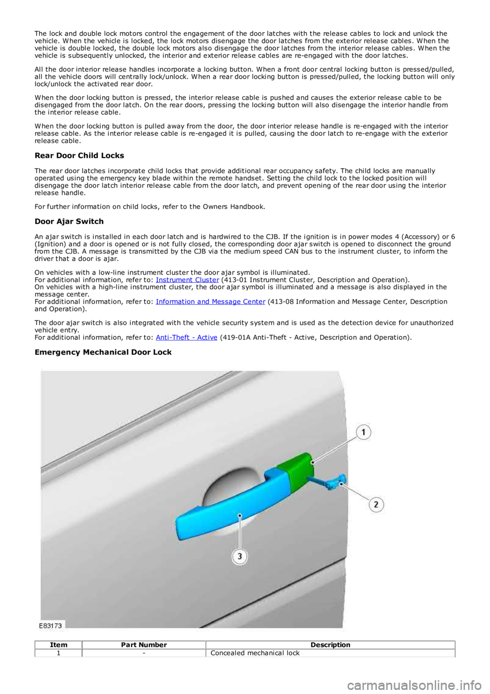
Emergency Mechanical Door Lock
ItemPart NumberDescription1-Conceal ed mechani cal lock
Page 2310 of 3229
2-Emergency key blade3-LH front door handl eThe remote hands et cont ai ns an emergency key blade, conceal ed in t he key fob. The front LH exterior door handleincorporates a mechanical operated door lock that i s conceal ed behind a removable plas ti c cover. The door lock all ows thefront LH door to be mechanicall y unlocked and locked us ing t he emergency key blade in the event that the remote cent rallocki ng operation fai ls, or a vehicl e power fai lure occurs.
W hen the mechanical door lock is us ed t he central l ocking syst em wil l not operat e, and if al ready armed the vehicle al armwi ll s ound when the door is opened. The vehicl e i s not abl e to be doubl e l ocked, or the al arm syst em armed usi ng theemergency key blade.
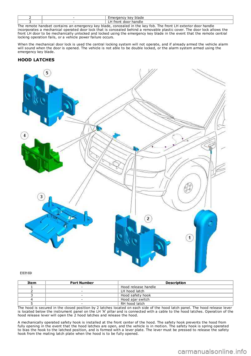
HOOD LATCHES
ItemPart NumberDescription1-Hood release handle2-LH hood lat ch3-Hood s afet y hook4-Hood ajar s witch5-RH hood latchThe hood is s ecured in the clos ed posi tion by 2 latches locat ed on each si de of t he hood l at ch panel. The hood rel ease leveris located bel ow t he inst rument panel on t he LH 'A' pi llar and i s connect ed wit h a cable to t he hood l at ches . Operati on of t hehood releas e lever will open t he 2 hood lat ches and releas e the hood.
A mechanicall y operated safety hook i s i ns talled at the front center of t he hood. The safety hook prevent s t he hood fromfully opening in the event t hat the hood latches are open, and the vehicle is in motion. The safety hook i s s pring operatedto bi as the hook t o t he l atched posi tion, and is formed wit h a lever plat e. The lever must be press ed to release the safetyhook from t he mating lat ch plat e when t he hood is to be full y opened.
Page 2311 of 3229
Hood Ajar Switch
The RH hood lat ch incorporat es the hood ajar s wi tch t hat is hardwired t o t he CJB. If t he i gniti on is in power modes 4(Acces sory) or 6 (Ignit ion) and the hood is opened or is not ful ly closed, t he hood ajar switch is opened t o dis connect theground from t he CJB. A mess age i s trans mitt ed by t he CJB via the medi um s peed CAN bus t o the i ns trument clust er, toinform the dri ver t hat the hood is ajar.
On vehicl es with a low-li ne inst rument clus ter t he hood ajar symbol is i llumi nated.For addit ional informat ion, refer t o: Inst rument Clus ter (413-01 Ins trument Clust er, Des cription and Operat ion).On vehicl es with a high-l ine i ns trument clust er, t he hood ajar s ymbol is il luminat ed and a mes sage i s als o dis pl ayed in t hemess age cent er.For addit ional informat ion, refer t o: Informat ion and Mes sage Center (413-08 Informati on and Mes sage Center, Descriptionand Operat ion).
The hood ajar s wi tch i s als o i nt egrated wit h the vehicle securit y system and is used as the detecti on device for unauthorizedvehicle ent ry.For addit ional informat ion, refer t o: Anti -Theft - Act ive (419-01A Anti-Theft - Act ive, Description and Operat ion).
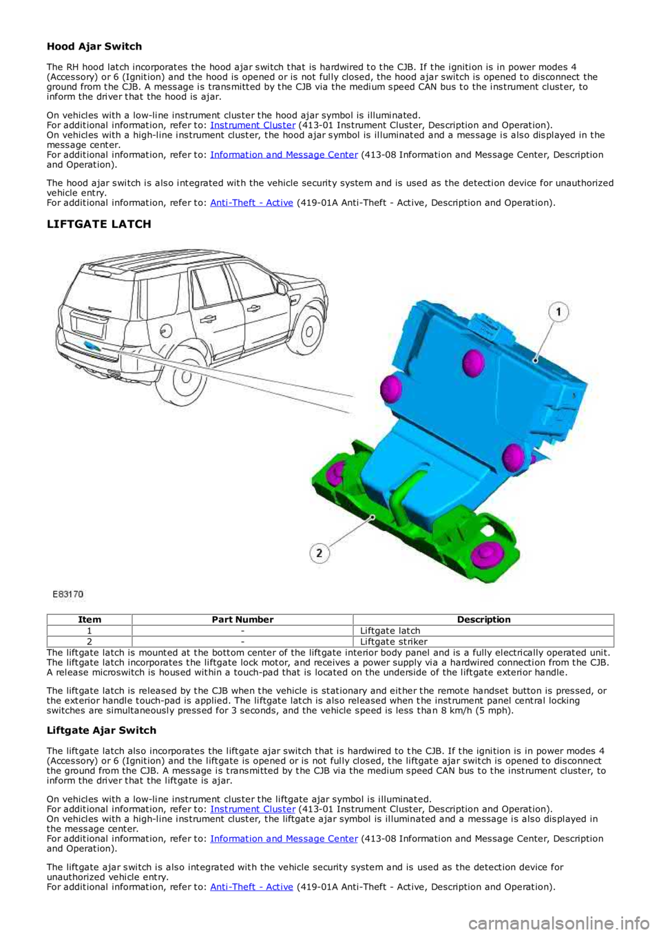
LIFTGATE LATCH
ItemPart NumberDescription
1-Li ftgat e lat ch2-Li ftgat e st rikerThe lift gate latch is mount ed at t he bott om center of the lift gate interior body panel and is a fully el ectri cally operat ed uni t.The lift gate latch incorporates t he li ftgate lock mot or, and receives a power supply vi a a hardwired connecti on from t he CJB.A rel ease microswitch is hous ed wit hin a touch-pad that is located on the unders ide of the l ift gate exteri or handle.
The lift gate latch is released by t he CJB when t he vehicle is st at ionary and eit her t he remot e handset button is pres sed, orthe ext erior handl e t ouch-pad is applied. The li ftgat e lat ch is als o rel eased when the inst rument panel cent ral lockingswitches are simultaneousl y press ed for 3 seconds, and the vehicle s peed is less t han 8 km/h (5 mph).
Liftgate Ajar Switch
The lift gate latch als o incorporates the l ift gate ajar swit ch that i s hardwired to the CJB. If t he igni tion is in power modes 4(Acces sory) or 6 (Ignit ion) and the l ift gate is opened or is not ful ly cl os ed, t he li ftgat e ajar swit ch is opened t o dis connectthe ground from the CJB. A mes sage i s t rans mi tted by t he CJB vi a t he medium s peed CAN bus t o t he inst rument cluster, toinform the dri ver t hat the l ift gate is ajar.
On vehicl es with a low-li ne inst rument clus ter t he li ftgate ajar symbol i s i lluminated.For addit ional informat ion, refer t o: Inst rument Clus ter (413-01 Ins trument Clust er, Des cription and Operat ion).On vehicl es with a high-l ine i ns trument clust er, t he liftgat e ajar symbol is il luminated and a message i s als o dis pl ayed inthe mess age cent er.For addit ional informat ion, refer t o: Informat ion and Mes sage Center (413-08 Informati on and Mes sage Center, Descriptionand Operat ion).
The lift gate ajar s wi tch i s als o int egrated wit h the vehicle securit y system and is used as the detect ion device forunauthorized vehi cle ent ry.For addit ional informat ion, refer t o: Anti -Theft - Act ive (419-01A Anti-Theft - Act ive, Description and Operat ion).