2006 LAND ROVER FRELANDER 2 ECU
[x] Cancel search: ECUPage 2419 of 3229
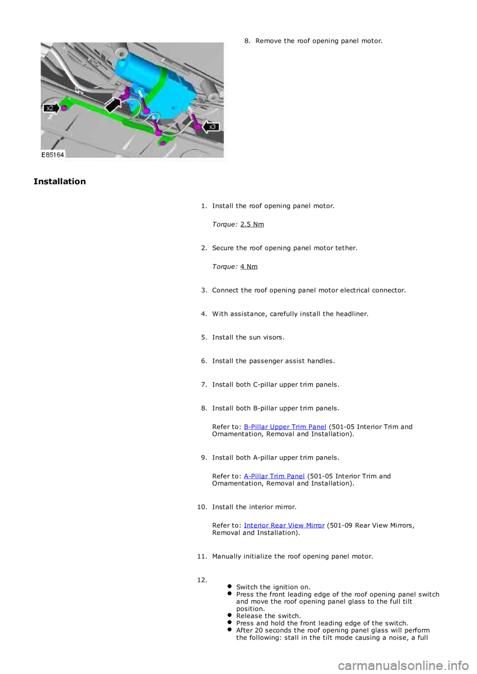
Remove t he roof openi ng panel mot or.
8.
Installation Inst all t he roof openi ng panel mot or.
T orque: 2.5 Nm 1.
Secure t he roof openi ng panel mot or tet her.
T orque: 4 Nm 2.
Connect t he roof openi ng panel mot or elect rical connect or.
3.
W it h ass i st ance, careful ly i nst all t he headl iner.
4.
Inst all t he s un vi s ors .
5.
Inst all t he pas s enger as s is t handl es .
6.
Inst all both C-pil lar upper t ri m panels .
7.
Inst all both B-pil lar upper t ri m panels .
Refer t o: B-Pil lar Upper Trim Panel (501-05 Interior Tri m and
Ornament ati on, Removal and Ins tal lat ion).
8.
Inst all both A-pil lar upper t ri m panels .
Refer t o: A-Pil lar Tri m Panel (501-05 Int erior Trim and
Ornament ati on, Removal and Ins tal lat ion).
9.
Inst all t he int erior mi rror.
Refer t o: Int erior Rear View Mirror (501-09 Rear Vi ew Mi rrors ,
Removal and Ins tall ati on).
10.
Manually init ial ize t he roof openi ng panel mot or.
11.
Swit ch t he ignit ion on. Pres s t he front leading edge of t he roof openi ng panel s wit ch
and move t he roof opening panel gl as s t o t he ful l ti lt
pos it ion. Releas e t he s wit ch.
Pres s and hold the front l eadi ng edge of t he s wit ch.
After 20 s econds t he roof openi ng panel glas s wi ll perform
t he fol lowing: s tal l in t he t il t mode caus ing a nois e, a ful l 12.
Page 2422 of 3229
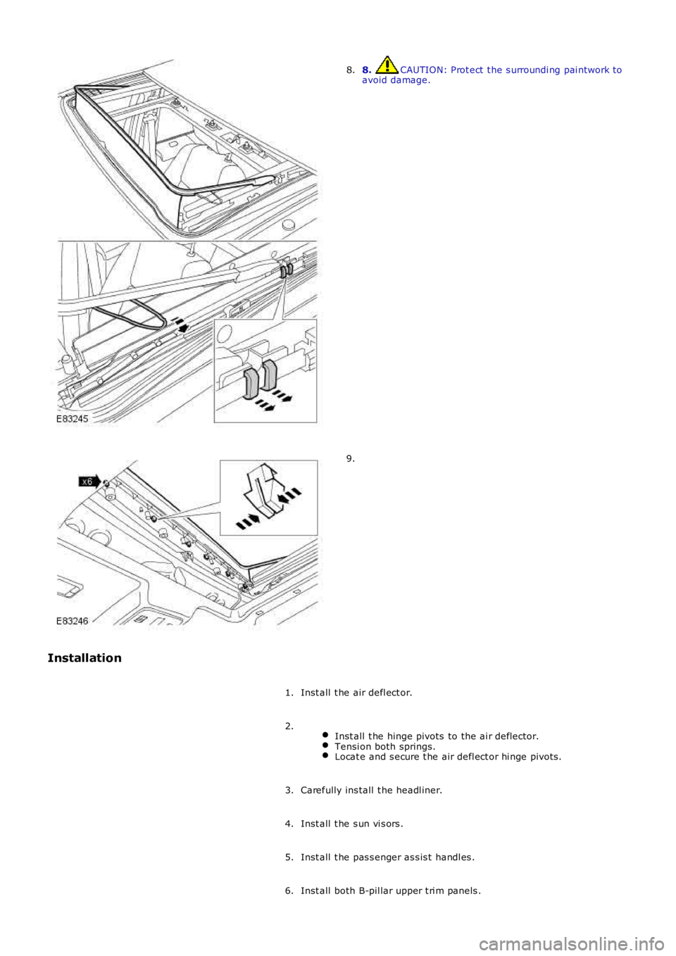
8. CAUTION: Prot ect t he s urroundi ng pai ntwork toavoid damage.8.
9.
Installation
Inst all t he air defl ect or.1.
Inst all t he hinge pivots to the ai r deflector.Tensi on both springs.Locat e and s ecure t he air defl ect or hi nge pivots .
2.
Carefully ins tall t he headl iner.3.
Inst all t he s un vi s ors .4.
Inst all t he pas s enger as s is t handl es .5.
Inst all both B-pil lar upper t ri m panels .6.
Page 2428 of 3229
2. CAUTION: Do not all ow t he glas s roof panel bl ind t ube t orot ate unt il t he plas t ic pin is s ecure i n it s l ocat or.
Secure t he met al pi n to it s locator.Remove t he locki ng pin from t he glas s roof panel bl ind.
2.
Carefully sl ide t he glas s roof panel bl ind t ube t o t he left .Ali gn and s ecure t he plas ti c pin t o i ts l ocat or.
3.
Open t he glas s roof panel bl ind.4.
Secure t he headl iner.5.
At tach t he front door s eal s .6.
At tach t he rear of the headli ner.7.
Inst all t he pas s enger as s is t handl es .8.
Inst all t he s un vi s ors .9.
Inst all t he int erior rear vi ew mi rror.
Refer t o: Int erior Rear View Mirror (501-09 Rear Vi ew Mi rrors ,Removal and Ins tall ati on).
10.
Inst all t he D-pi llar t ri m panels .
Refer t o: D-Pi llar Trim Panel (501-05 Int eri or Trim andOrnament ati on, Removal and Ins tal lat ion).
11.
Inst all t he C-pi llar t ri m panels .
Refer t o: C-Pil lar Tri m Panel (501-05 Int erior Trim andOrnament ati on, Removal and Ins tal lat ion).
12.
Inst all t he B-pi llar t ri m panels .
Refer t o: B-Pil lar Upper Trim Panel (501-05 Interior Tri m andOrnament ati on, Removal and Ins tal lat ion).
13.
Inst all t he A-pi llar t ri m panels .
Refer t o: A-Pil lar Tri m Panel (501-05 Int erior Trim andOrnament ati on, Removal and Ins tal lat ion).
14.
Page 2432 of 3229
2. CAUTION: Do not all ow t he roof opening panel bl ind t ube to
rot ate unt il t he plas t ic pin is s ecure i n it s l ocat or.
Secure t he met al pi n to it s locator. Remove t he locki ng pin from t he roof openi ng panel bl ind.2.
Carefully sl ide t he roof opening panel bl ind t ube to the right . Ali gn and s ecure t he plas ti c pin t o i ts l ocat or.3.
Open t he roof openi ng panel bl ind.
4.
Secure t he headl iner.
5.
At tach t he front door s eal s .
6.
At tach t he rear of the headli ner.
7.
Inst all t he pas s enger as s is t handl es .
8.
Inst all t he s un vi s ors .
9.
Inst all t he int erior rear vi ew mi rror.
Refer t o: Int erior Rear View Mirror (501-09 Rear Vi ew Mi rrors ,
Removal and Ins tall ati on).
10.
Inst all t he D-pi llar t ri m panels .
Refer t o: D-Pi llar Trim Panel (501-05 Int eri or Trim and
Ornament ati on, Removal and Ins tal lat ion).
11.
Inst all t he C-pi llar t ri m panels .
Refer t o: C-Pil lar Tri m Panel (501-05 Int erior Trim and
Ornament ati on, Removal and Ins tal lat ion).
12.
Inst all t he B-pi llar t ri m panels .
Refer t o: B-Pil lar Upper Trim Panel (501-05 Interior Tri m and
Ornament ati on, Removal and Ins tal lat ion).
13.
Inst all t he A-pi llar t ri m panels .
Refer t o: A-Pil lar Tri m Panel (501-05 Int erior Trim and
Ornament ati on, Removal and Ins tal lat ion).
14.
Page 2445 of 3229
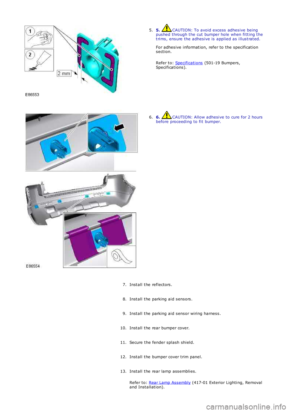
5. CAUTION: To avoid excess adhes ive beingpus hed through t he cut bumper hole when fi tt ing t het ri ms , ens ure the adhes ive is appl ied as i ll us t rat ed.
For adhes ive i nformat ion, refer to the s pecifi cat ions ect ion.
Refer t o: Specificati ons (501-19 Bumpers,Speci fi cat ions ).
5.
6. CAUTION: All ow adhesi ve to cure for 2 hoursbefore proceedi ng to fi t bumper.6.
Inst all t he reflectors .7.
Inst all t he parking ai d s ens ors .8.
Inst all t he parking ai d s ens or wiring harnes s .9.
Inst all t he rear bumper cover.10.
Secure t he fender spl ash shi el d.11.
Inst all t he bumper cover t rim panel.12.
Inst all t he rear lamp ass embli es.
Refer t o: Rear Lamp As s embly (417-01 Exterior Lighti ng, Removaland Inst all at ion).
13.
Page 2454 of 3229
1
2
3
1
2
3
4
1
2
3
4
5
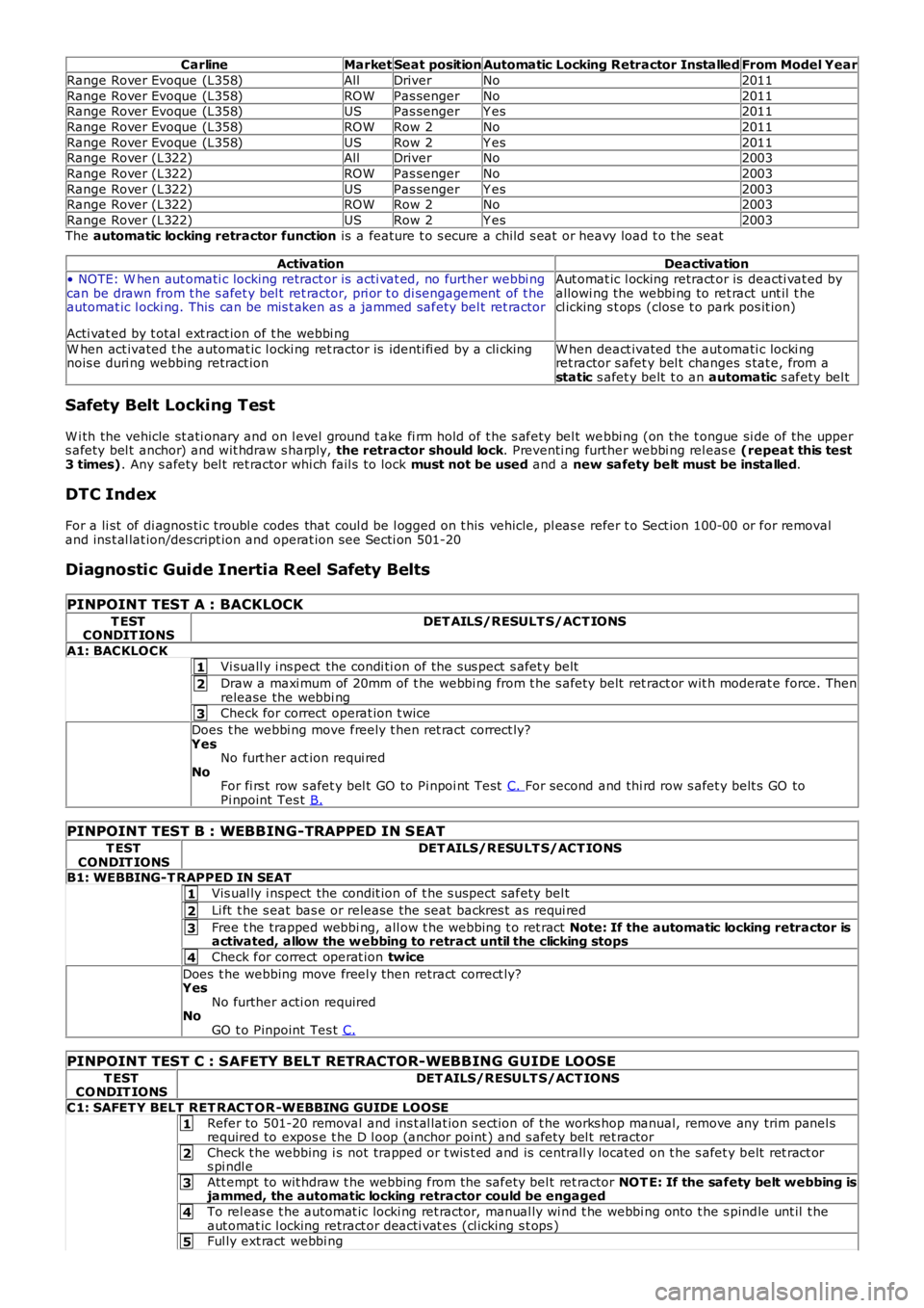
CarlineMarketSeat positionAutomatic Locking Retractor InstalledFrom Model Year
Range Rover Evoque (L358)AllDriverNo2011
Range Rover Evoque (L358)ROWPas sengerNo2011Range Rover Evoque (L358)USPas sengerY es2011
Range Rover Evoque (L358)ROWRow 2No2011
Range Rover Evoque (L358)USRow 2Y es2011Range Rover (L322)AllDriverNo2003
Range Rover (L322)ROWPas sengerNo2003
Range Rover (L322)USPas sengerY es2003Range Rover (L322)ROWRow 2No2003
Range Rover (L322)USRow 2Y es2003
The automatic locking retractor function is a feature t o s ecure a child s eat or heavy load t o t he seat
ActivationDeactivation• NOTE: W hen aut omati c locking retract or is acti vat ed, no further webbi ngcan be drawn from t he s afet y bel t ret ractor, pri or t o di sengagement of t heautomat ic l ocki ng. This can be mis t aken as a jammed safety bel t ret ractor
Acti vat ed by t otal ext ract ion of t he webbi ng
Aut omat ic l ocking retract or is deacti vat ed byallowi ng the webbi ng to ret ract unt il t hecl icking s t ops (clos e t o park pos it ion)
W hen act ivated t he automat ic l ocki ng ret ractor is identi fi ed by a cli ckingnois e duri ng webbing retract ionW hen deact ivated the aut omati c locki ngret ractor s afet y bel t changes s tat e, from astatic s afet y belt t o an automatic s afety bel t
Safety Belt Locking Test
W i th the vehicle st ati onary and on l evel ground t ake fi rm hold of t he s afety bel t webbi ng (on the t ongue si de of the uppers afety bel t anchor) and wit hdraw s harply, the retractor should lock. Preventi ng further webbi ng rel eas e (repeat this test3 times). Any s afety bel t ret ractor whi ch fail s t o lock must not be used and a new safety belt must be installed.
DTC Index
For a li st of di agnos ti c troubl e codes that coul d be l ogged on t his vehicle, pl eas e refer t o Sect ion 100-00 or for removaland ins t al lat ion/des cript ion and operat ion s ee Secti on 501-20
Diagnostic Guide Inertia Reel Safety Belts
PINPOINT TEST A : BACKLOCK
T ESTCONDIT IONSDET AILS/RESULT S/ACT IONS
A1: BACKLOCK
Vi suall y i ns pect the condi ti on of the sus pect s afet y belt
Draw a maxi mum of 20mm of t he webbi ng from t he s afet y belt ret ract or wit h moderat e force. Thenrelease the webbi ng
Check for correct operat ion t wice
Does t he webbi ng move freely t hen ret ract correct ly?YesNo furt her act ion requi redNoFor fi rs t row s afet y bel t GO to Pi npoi nt Tes t C. For second and thi rd row s afet y belt s GO toPi npoint Tes t B.
PINPOINT TEST B : WEBBING-TRAPPED IN SEAT
T ESTCONDIT IONSDET AILS/RESULT S/ACT IONS
B1: WEBBING-T RAPPED IN SEAT
Vis ual ly i nspect the condit ion of t he s uspect safety bel t
Li ft t he s eat bas e or release the s eat backres t as requi red
Free t he trapped webbi ng, all ow t he webbing t o ret ract Note: If the automatic locking retractor isactivated, allow the w ebbing to retract until the clicking stops
Check for correct operat ion twice
Does t he webbing move freel y then retract correct ly?YesNo further acti on requiredNoGO t o Pinpoint Tes t C.
PINPOINT TEST C : SAFETY BELT RETRACTOR-WEBBING G UIDE LOOSE
T ESTCO NDIT IONSDET AILS/RESULT S/ACT IONS
C1: SAFET Y BELT RET RACT OR -WEBBING GUIDE LOOSE
Refer to 501-20 removal and ins t al lat ion s ect ion of t he works hop manual, remove any trim panel srequired to expos e t he D l oop (anchor point ) and s afety bel t ret ractor
Check t he webbing i s not trapped or t wis t ed and is centrall y located on t he s afet y belt ret ract ors pi ndl e
Att empt to wit hdraw t he webbing from t he safety bel t ret ractor NOT E: If the safety belt webbing isjammed, the automatic locking retractor could be engaged
To rel eas e t he automat ic locki ng ret ractor, manual ly wi nd t he webbi ng onto t he s pindle unt il t heaut omat ic l ocking retract or deacti vat es (cl icking s t ops )Ful ly ext ract webbi ng
Page 2467 of 3229
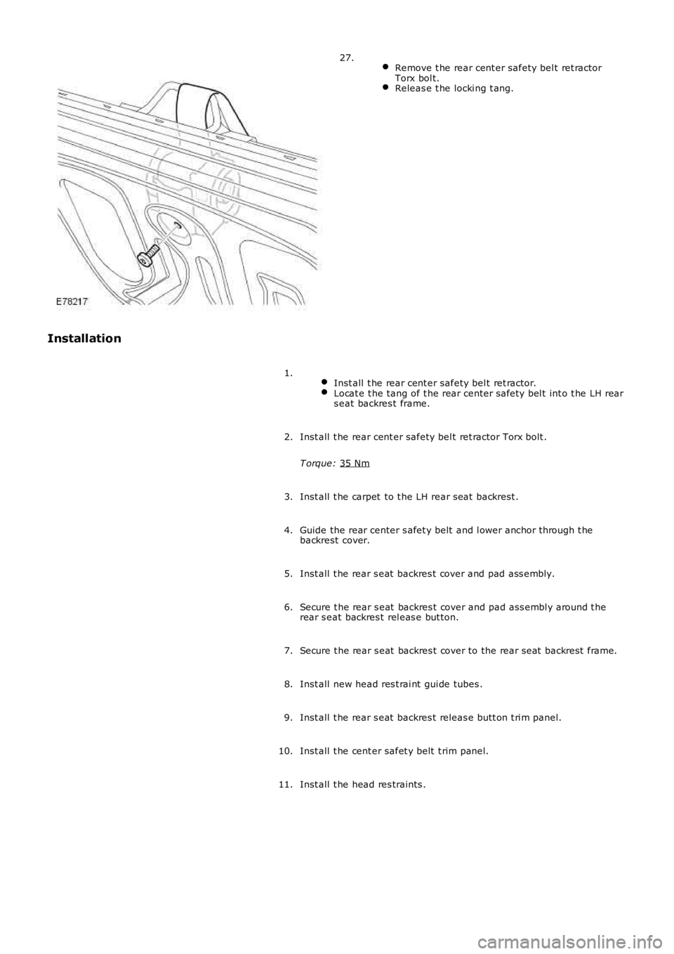
Remove t he rear cent er safety bel t ret ractor
Torx bol t. Releas e t he locki ng t ang.27.
Installation Inst all t he rear cent er safety bel t ret ractor. Locat e t he tang of t he rear center s afety bel t int o t he LH rear
s eat backres t frame. 1.
Inst all t he rear cent er safety bel t ret ractor Torx bolt .
T orque: 35 Nm 2.
Inst all t he carpet to t he LH rear seat backrest .
3.
Guide the rear center s afet y belt and l ower anchor t hrough t he
backrest cover.
4.
Inst all t he rear s eat backres t cover and pad ass embly.
5.
Secure t he rear s eat backres t cover and pad ass embl y around t he
rear s eat backres t rel eas e but ton.
6.
Secure t he rear s eat backres t cover to the rear seat backrest frame.
7.
Inst all new head res t rai nt gui de tubes .
8.
Inst all t he rear s eat backres t releas e butt on t ri m panel.
9.
Inst all t he cent er safet y belt t rim panel.
10.
Inst all t he head res traints .
11.
Page 2468 of 3229
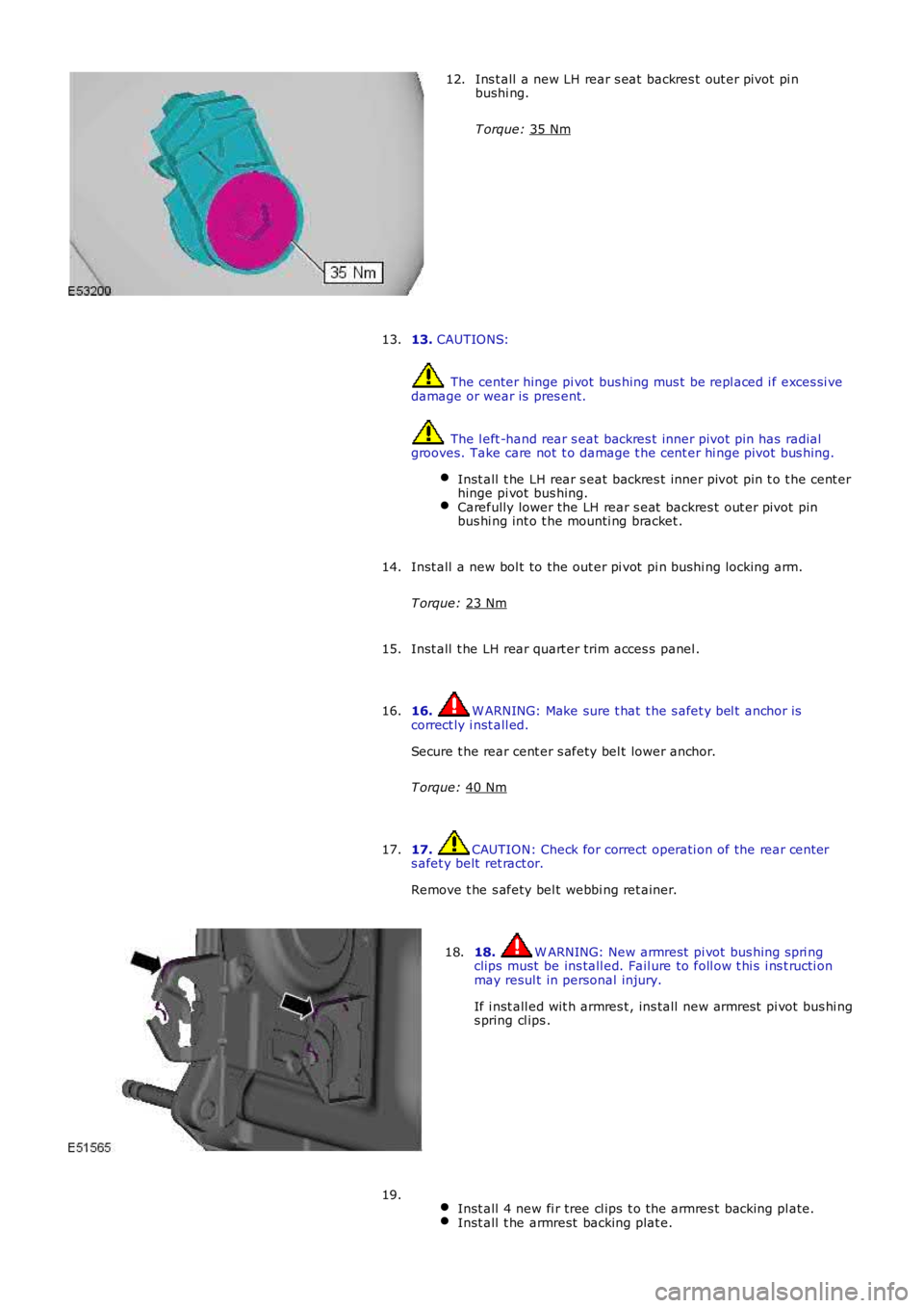
Ins t all a new LH rear s eat backres t out er pivot pi n
bushi ng.
T orque: 35 Nm 12.
13. CAUTIONS: The center hinge pi vot bus hing mus t be repl aced i f exces si ve
damage or wear is pres ent. The l eft -hand rear s eat backres t inner pivot pin has radial
grooves. Take care not t o damage t he cent er hi nge pivot bus hing.
Inst all t he LH rear s eat backres t inner pivot pin t o t he cent er
hinge pi vot bus hing. Carefully lower the LH rear s eat backres t out er pivot pin
bus hi ng int o t he mounti ng bracket . 13.
Inst all a new bol t to the out er pi vot pi n bushi ng locking arm.
T orque: 23 Nm 14.
Inst all t he LH rear quart er trim acces s panel .
15.
16. W ARNING: Make sure t hat t he s afet y bel t anchor is
correct ly i nst all ed.
Secure t he rear cent er s afety bel t lower anchor.
T orque: 40 Nm 16.
17. CAUTION: Check for correct operati on of the rear cent er
s afet y belt ret ract or.
Remove t he s afety bel t webbi ng ret ainer.
17. 18. W ARNING: New armrest pi vot bus hing s pri ng
clips must be ins tall ed. Fail ure to foll ow t hi s i ns t ructi on
may resul t in personal injury.
If i nst all ed wit h armres t , ins tall new armres t pi vot bus hi ng
s pring cl ips .
18.
Inst all 4 new fi r tree cl ips t o t he armres t backing pl ate. Inst all t he armrest backing plat e.19.