2006 LAND ROVER FRELANDER 2 ECU
[x] Cancel search: ECUPage 2485 of 3229
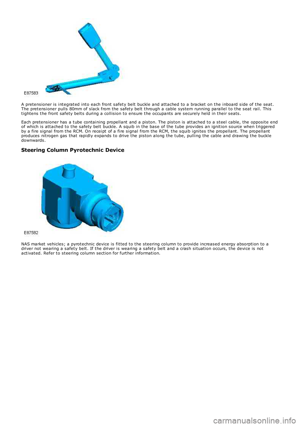
A pretens ioner i s i nt egrat ed int o each front s afet y belt buckl e and att ached to a bracket on t he i nboard s ide of t he seat .The pret ens i oner pull s 80mm of s lack from the safet y belt t hrough a cable sys tem running parallel t o t he s eat rail . Thi st ightens t he front safety belt s duri ng a coll is ion t o ens ure t he occupants are s ecurely held in t heir s eats .
Each pretens ioner has a t ube contai ning propell ant and a pis ton. The pis t on is at t ached t o a s t eel cable, the oppos it e endof which i s att ached t o t he s afety bel t buckle. A squib in the bas e of the tube provi des an ignit ion s ource when t ri ggeredby a fire s ignal from t he RCM. On recei pt of a fi re s i gnal from the RCM, t he s qui b igni tes t he propell ant . The propell antproduces ni trogen gas that rapi dl y expands t o dri ve t he pis ton al ong the t ube, pul ling the cable and drawing t he buckl edownwards .
Steering Column Pyrotechnic Device
NAS market vehicles ; a pyrot echnic device i s fit ted t o t he s teering column t o provi de increas ed energy absorpti on to adri ver not weari ng a s afet y belt . If t he dri ver i s weari ng a s afet y belt and a cras h s i tuati on occurs, t he devi ce is notact ivat ed. Refer t o s t eering column sect ion for furt her informati on.
Page 2510 of 3229
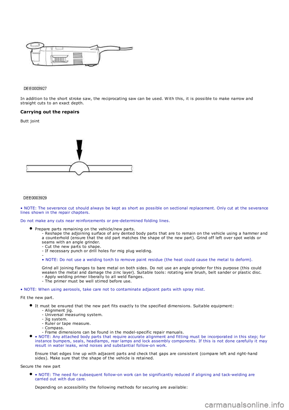
In addi ti on t o the short st roke s aw, t he reciprocati ng s aw can be us ed. W it h t his , it i s poss i bl e t o make narrow ands traight cut s t o an exact depth.
Carrying out the repairs
Butt joint
• NOTE: The s everance cut s houl d always be kept as s hort as poss i bl e on s ecti onal repl acement. Onl y cut at t he s everanceli nes shown in t he repair chapters.
Do not make any cuts near rei nforcements or pre-determined folding lines .
Prepare parts remaini ng on t he vehi cl e/new parts .- Res hape t he adjoi ni ng s urface of any dented body part s t hat are t o remai n on t he vehicle us ing a hammer anda count erhold (ens ure t hat the ol d part mat ches the s hape of the new part ). Grind off left over s pot wel ds ors eams wit h an angle grinder.- Cut the new part s to s hape.- If neces sary punch or drill holes for mig plug wel di ng.-• NOTE: Do not us e a wel ding t orch t o remove pai nt res idue (the heat coul d caus e t he met al to deform).
Gri nd all joining flanges to bare met al on both s i des . Do not us e an angle grinder for t hi s purpos e (this couldweaken the met al and damage the zi nc layer). Sui table tools : rot ati ng wi re brush, belt s ander or plas t ic dis c.- Apply wel di ng pri mer li berall y to all weld flanges .- The pri mer mus t be well s t irred before us e.
• NOTE: W hen us ing aerosol s, t ake care not t o cont aminat e adjacent part s wi th spray mi st .
Fit t he new part .
It must be ens ured that t he new part fit s exact ly t o t he s pecified di mensi ons. Suit able equipment :- Ali gnment jig.- Univers al meas uring s ys tem.- Jig s ys tem.- Ruler or tape meas ure.- Compass .- Frame dimens ions can be found i n t he model-specific repai r manual s.• NOTE: Any att ached body part s t hat require accurat e ali gnment and fit t ing mus t be i ncorporat ed i n t hi s s tep; forins t ance bumpers , s eal s , headlamps , rear l amps and lock as sembl y components . If thi s is not done careful ly i t mayres ult i n wat er l eaks , wi nd noi s es and subs tant ial fol low-on work.
Ensure t hat edges li ne up wi th adjacent part s and check t hat gaps are cons is t ent (compare l eft and right-hands ides ). Make s ure that the shape of t he vehi cl e is ret ai ned.
Secure t he new part
• NOTE: The need for s ubsequent foll ow-on work can be s ignificantl y reduced if ali gni ng and t ack-wel ding arecarri ed out wit h due care.
Dependi ng on acces si bili ty the foll owing met hods for s ecuri ng are avai lable:
Page 2514 of 3229
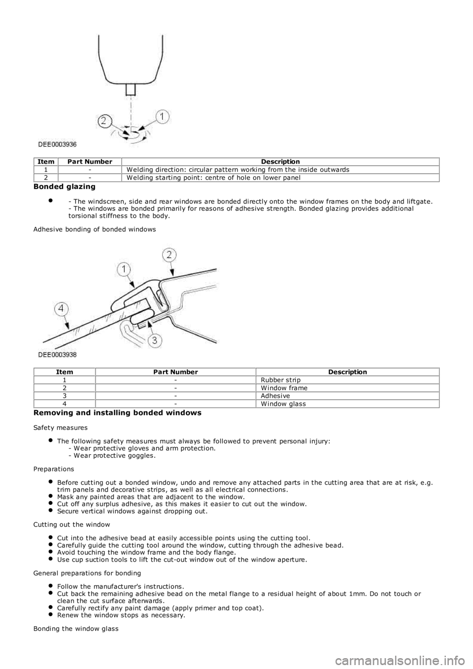
ItemPart NumberDescription
1-W el ding direct ion: circul ar pat tern worki ng from t he ins ide out wards
2-W el ding s tarti ng point: centre of hole on lower panel
Bonded glazing
- The wi nds creen, si de and rear wi ndows are bonded di rectl y onto the window frames on t he body and li ft gat e.- The wi ndows are bonded primaril y for reas ons of adhes ive st rength. Bonded glazing provi des addit ionalt ors ional s t iffnes s to the body.
Adhes i ve bonding of bonded windows
ItemPart NumberDescription
1-Rubber s t ri p
2-W i ndow frame3-Adhes i ve
4-W i ndow glas s
Removing and installing bonded windows
Safet y measures
The fol lowing safety meas ures must al ways be foll owed t o prevent personal injury:- W ear prot ect ive gl oves and arm protecti on.- W ear prot ect ive goggles .
Preparat ions
Before cut t ing out a bonded window, undo and remove any att ached parts in t he cutt ing area that are at ri sk, e.g.t rim panels and decorati ve s trips , as well as all elect rical connecti ons .Mas k any pai nted areas that are adjacent t o t he window.Cut off any s urplus adhes ive, as this makes it eas ier to cut out t he window.Secure vert ical windows agai nst droppi ng out .
Cutt ing out t he window
Cut int o t he adhes ive bead at easi ly access ibl e point s usi ng t he cut ti ng t ool .Careful ly gui de the cut ti ng tool around t he window, cut t ing t hrough the adhes ive bead.Avoi d t ouching the wi ndow frame and t he body fl ange.Us e cup s uct ion t ools t o l ift the cut-out window out of the window apert ure.
General preparati ons for bondi ng
Follow the manufact urer's i ns t ructi ons .Cut back t he remaining adhesi ve bead on t he metal flange to a res i dual height of about 1mm. Do not touch orclean t he cut s urface aft erwards .Careful ly rect ify any paint damage (appl y pri mer and top coat).Renew t he window s t ops as neces sary.
Bondi ng t he window gl as s
Page 2515 of 3229
Apply an even bead of adhes ive t o t he wi ndow or t o t he body fl ange.Ins ert the wi ndow glas s int o t he window apert ure and cent re i t (2 technicians required).Check t he gaps.• NOTE: Open t he windows and doors whi le the wi ndow is left t o dry and do not move the vehi cl e (sl amming doorscreates excess press ure which could cause the window t o become loos e).
Us e adhes i ve tape t o prevent the window from fall ing out or s li ppi ng.
Finis hing operat ions
Reconnect al l el ect ri cal connect ions and check t hat t he component s operate correctl y.Ins t all the at t ached part s and check t hat the fit i s accurat e and s ecure.- Carry out a vis ual ins pect ion t o ensure t hat t he gaps and joi nts are even.Thoroughl y clean t he window gl as s .
Protective equipment and safety at work
Vari ous safet y meas ures and l egal requi rements mus t be met when carryi ng out repairs. Al l regulati ons relat ing t oheal th and s afety at work mus t be followed.
W el di ng s afet y precaut ions
The fol lowing safety precauti ons mus t be observed to prevent t he ri s k of pers onal injury:- Safet y hood (face protecti on).- W el ding s hield.- Safet y gloves.- Safet y s hoes .- Extract ion unit for welding smoke.W el di ng s houl d always be carried out i n well venti lated areas. A fi re ext inguis her must al so always be wi thin reach.
General body repair safety measures
Extract ion unit
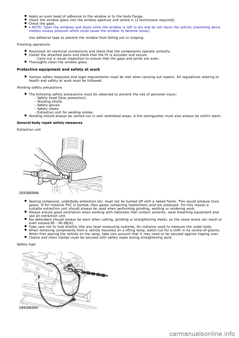
Seal ing compound, underbody prot ect ion et c. must not be burned off wit h a naked flame. This would produce toxicgases . If for ins tance PVC i s burned, then gas es cont ai ning hydrochlori c aci d are produced. For this reas on as uit abl e extract ion unit s hould al ways be used when performing grinding, weldi ng or sol dering work.Always ens ure good venti lati on when worki ng wit h mat eri al s t hat contai n s olvent s , wear breat hing equipment andus e an extract ion unit .Ear defenders s houl d always be worn when cutt ing, gri ndi ng or st rai ght ening met al, as t he nois e l evels can reach oreven exceed 85 - 90 dB(A).Take care not to look direct ly into any las er meas uri ng s yst ems , for ins t ance us ed to meas ure t he under body.W hen removing component s from a vehi cl e mounted on a li ft ing ramp, watch out for a shi ft i n i ts centre-of-gravi ty.W hen firs t pl aci ng t he vehi cl e on t he ramp, t ake int o account that it may need to be s ecured agains t t ipping over.Chains and chai n clamps mus t be s ecured wi th safety ropes during s t raight eni ng work.
Safet y rope
Page 2703 of 3229
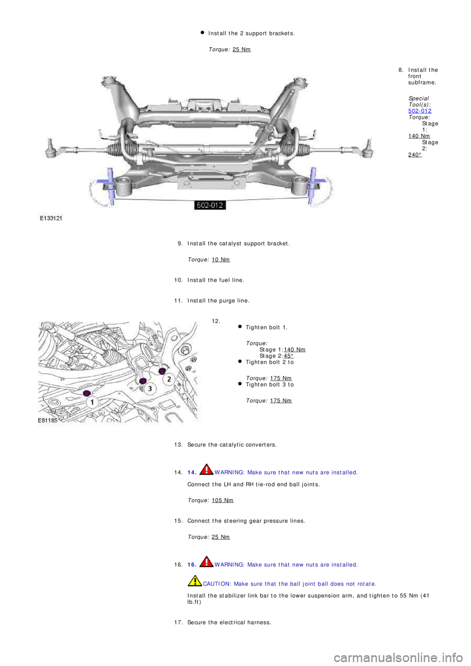
St a g e
1:
St a g e
2:
St a g e 1:
St a g e 2: Install the 2 support brackets.
Torque: 25 Nm
Install the
front
subframe.
Sp e c i a l
T ool (s ):
502-012
Torque:
140 Nm
240°
8.
Install the catalyst support bracket.
Torque: 10 Nm
9.
Install the fuel line. 10.
Install the purge line. 11.
Tighten bolt 1.
Torque:
140 Nm
45°Tighten bolt 2 to
Torque: 175 Nm
Tighten bolt 3 to
Torque: 175 Nm
12.
Secure the catalytic converters. 13.
14.
WARNING: Make sure that new nuts are installed.
Connect the LH and RH tie-rod end ball joints.
Torque: 105 Nm14.
Connect the steering gear pressure lines.
Torque: 25 Nm
15.
16.
WARNING: Make sure that new nuts are installed.
CAUTION: Make sure that the ball joint ball does not rotate.
Install the stabilizer link bar to the lower suspension arm, and tighten to 55 Nm (41
lb.ft) 16.
Secure the electrical harness. 17.
Page 2704 of 3229
18. WARNING: Make sure that a new steering column flexible coupling bolt is
installed.
Connect the steering column to the steering gear.
Torque: 25 Nm18.
Connect and s ecure t he cat alys t moni t or s ens or el ect ri cal connect ors . 19.
Install the 2 subframe mounting bolts and remove the jack. 20.
Install the engine undershield.
Refer to: Engine Undershield
(501-02 Front End Body Panel s, Removal and
Installation). 21.
Install the wheels and tires.
Refer to: W heel and Tire
(204-04 W heels and Tires , Removal and Ins t all at i on). 22.
Refill and bleed the power steering.
Refer to: Power Steering System Bleeding
(211-00 St eeri ng Sys t em - General
Informat ion, General Procedures). 23.
Using only four wheel alignment equipment approved by Land Rover, check and adjust
the wheel alignment. 24.
Page 2715 of 3229
1. CAUTION: Make sure that new bolts are installed.
Clean the component mating faces.
With assistance, install the subframe.With assistance, align and secure the differential.Tighten the rear bolts.
Torque: 110 Nm
Tighten the front bolts.
Torque: 175 Nm
1.
2.
CAUTION: Make sure that new bolts are installed.
Align the suspension arms to the subframe and install the bolts, do
not fully tighten at this stage. 2.
Using the special tool, support the subframe. 3.
Connect the transmission breather lines. 4.
5. CAUTIONS:
Make sure that no components catch.
Make sure that new bolts are installed.
With assistance, position the subframe to the body and tighten the
bolts.
Torque: 175 Nm
5.
6.
CAUTION: Make sure that new bolts are installed.
Install the stabilizer clamp bolts, but do not tighten fully at this
stage. 6.
Connect the Active On-demand Coupling module electrical connector. 7.
Re mo ve t he p o we rt ra i n j a ck.
General Equi pment : P o w e rt ra i n Ja ck
8.
9.
CAUTION: Make sure that new bolts are installed.
Install the trailing arm to body brackets.
Torque: 110 Nm9.
10.
CAUTION: Make sure that the brake hose is not twisted
and is correctly located.
Clean the component mating faces.
Install the brake caliper anchor plate.
Torque: 110 Nm
Repeat the above procedure for the other side.
10.
Secure the wheel speed sensor and lead.
11.
Page 2716 of 3229
Torque: 5 NmSecure the lead in the clips.Repeat the above procedure for the other side.
LH side: Connect the ride height sensor electrical connector. 12.
Position and secure the rear shock absorbers.
Install both mass dampers.
Torque: 25 Nm
Repeat the above procedure for the other side.
13.
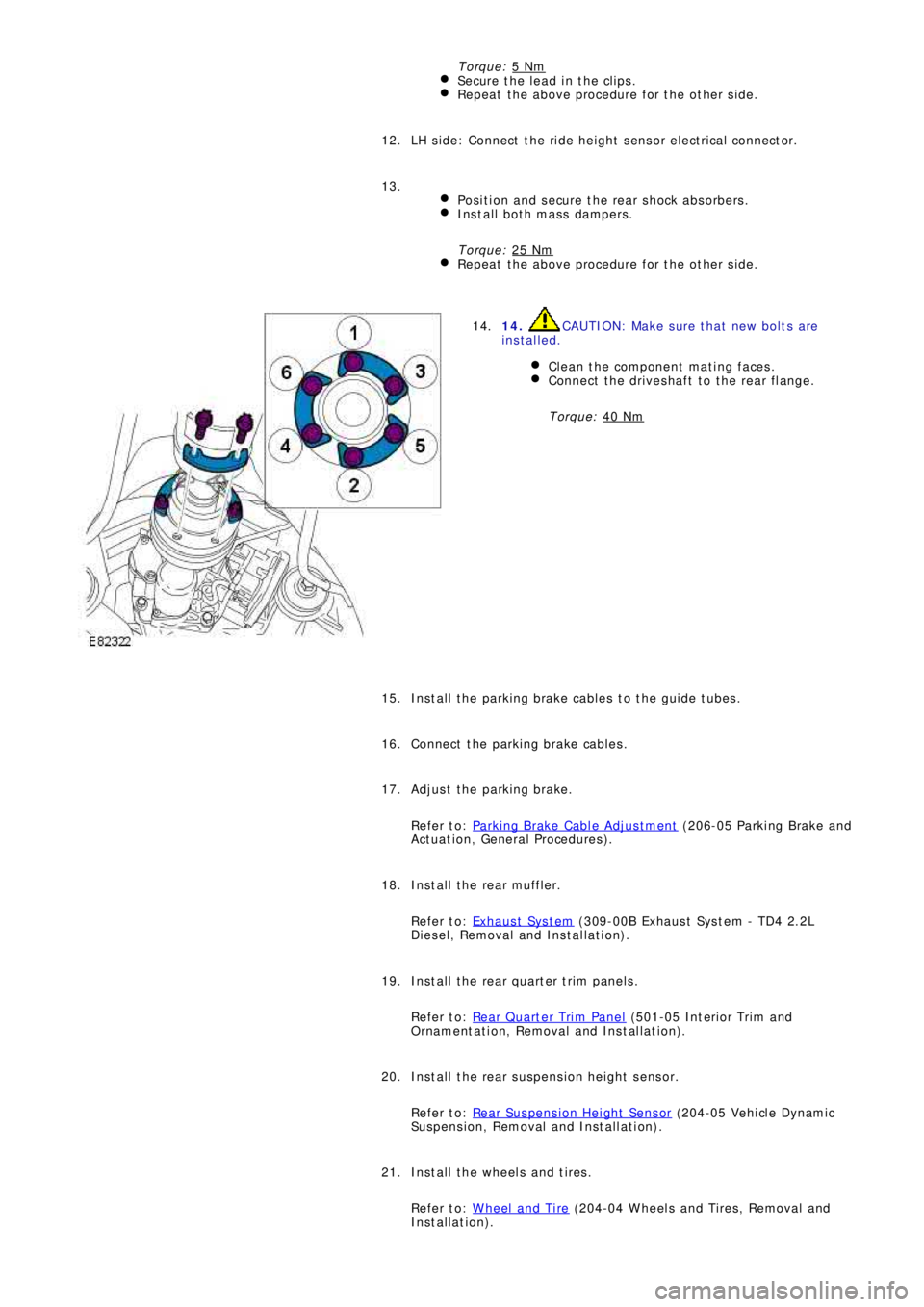
14. CAUTION: Make sure that new bolts are
installed.
Clean the component mating faces.
Connect the driveshaft to the rear flange.
Torque: 40 Nm
14.
Install the parking brake cables to the guide tubes. 15.
Connect the parking brake cables. 16.
Adjust the parking brake.
Refer to: Parking Brake Cable Adjustment
(206-05 Parki ng Brake and
Act uat i on, General Procedures ). 17.
Install the rear muffler.
Refer to: Exhaus t Sys t em
(309-00B Exhaus t Sys t em - TD4 2.2L
Diesel, Removal and Installation). 18.
Install the rear quarter trim panels.
Refer to: Rear Quarter Trim Panel
(501-05 Int eri or Tri m and
Ornament at i on, Removal and Ins t al lat i on). 19.
Install the rear suspension height sensor.
Refer to: Rear Suspension Height Sensor
(204-05 Vehi cl e Dynami c
Suspension, Removal and Installation). 20.
Install the wheels and tires.
Refer to: Wheel and Tire
(204-04 Wheels and Tires, Removal and
Installation). 21.