2006 LAND ROVER FRELANDER 2 ECU
[x] Cancel search: ECUPage 2903 of 3229
183
Wheels and tyres
R
USING WINTER TYRES
If winter tyres are fitted to the vehicle, the tyre
manufacturers instructions should be
followed. Pay particular attention to
instructions regarding the maximum speed
that the vehicle can be driven, and the correct
pressures for the tyres.
CHANGING A ROAD WHEEL
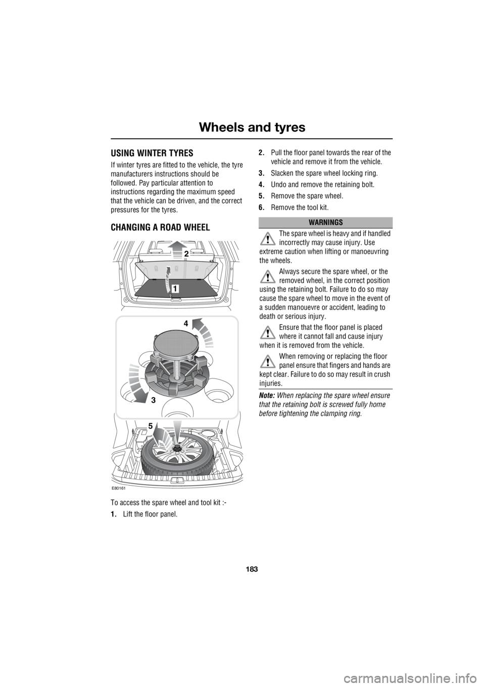
To access the spare wheel and tool kit :-
1. Lift the floor panel. 2.
Pull the floor panel towards the rear of the
vehicle and remove it from the vehicle.
3. Slacken the spare wheel locking ring.
4. Undo and remove the retaining bolt.
5. Remove the spare wheel.
6. Remove the tool kit.
Note: When replacing the spare wheel ensure
that the retaining bolt is screwed fully home
before tightening the clamping ring.
3
4
1
2
5
E80161
WARNINGS
The spare wheel is heavy and if handled
incorrectly may cause injury. Use
extreme caution when lifting or manoeuvring
the wheels.
Always secure the spare wheel, or the
removed wheel, in the correct position
using the retaining bolt. Failure to do so may
cause the spare wheel to move in the event of
a sudden manouevre or accident, leading to
death or serious injury.
Ensure that the floo r panel is placed
where it cannot fall and cause injury
when it is removed from the vehicle.
When removing or replacing the floor
panel ensure that fingers and hands are
kept clear. Failure to do so may result in crush
injuries.
Page 2907 of 3229
187
Wheels and tyres
R
Locking wheel nuts
Locking wheel nuts can only be removed using
the special adapter provided in the tool kit.
Note: When the vehicle is first supplied the
adapter may be stored in the glove
compartment. It should be removed and stored
in the tool kit as soon as possible.
Note: A code number is stamped onto the
underside of the adapter. This number must be
recorded on the security card supplied with the
literature pack. If a replacement adapter is
required you will be asked to quote this
number. The security card must be kept safe,
but should not be kept with the vehicle.
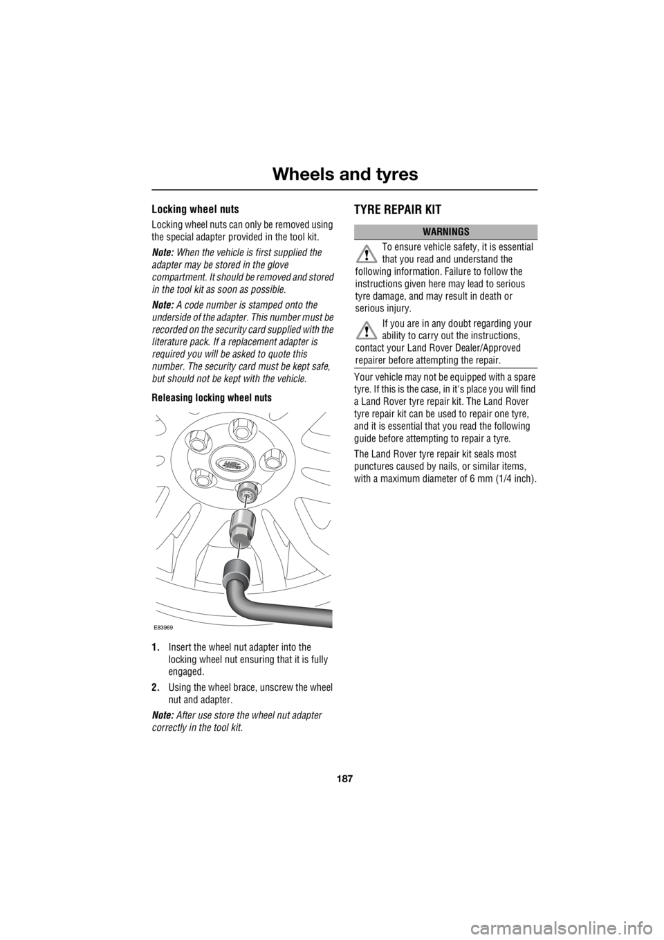
Releasing locking wheel nuts
1. Insert the wheel nut adapter into the
locking wheel nut ensuri ng that it is fully
engaged.
2. Using the wheel brace, unscrew the wheel
nut and adapter.
Note: After use store the wheel nut adapter
correctly in the tool kit.
TYRE REPAIR KIT
Your vehicle may not be equipped with a spare
tyre. If this is the case, in it's place you will find
a Land Rover tyre repair kit. The Land Rover
tyre repair kit can be us ed to repair one tyre,
and it is essential that you read the following
guide before attempting to repair a tyre.
The Land Rover tyre repair kit seals most
punctures caused by nails , or similar items,
with a maximum diameter of 6 mm (1/4 inch).
E83969
WARNINGS
To ensure vehicle safety, it is essential
that you read and understand the
following information. Failure to follow the
instructions given here may lead to serious
tyre damage, and may result in death or
serious injury.
If you are in any doubt regarding your
ability to carry out the instructions,
contact your Land Ro ver Dealer/Approved
repairer before attempting the repair.
Page 2911 of 3229
191
Wheels and tyres
R
12. During the inflation, switch the
compressor off briefly to check the tyre
pressure using the gauge mounted on the
compressor.
• It should not take longer than seven
minutes to inflate the tyre. If after seven
minutes the tyre ha s not reached the
minimum pressure, the tyre should not
be used.
13. Once the tyre has been inflated switch off
the compressor. If desired the engine may
be turned off after the compressor has
been turned off.
14. Remove the power connector from the
auxiliary power socket.
15. Remove the inflation hose from the tyre
valve by unscrewing it as quickly as
possible (anti-clockwise).
16. Replace the inflation hose protective cap,
and the tyre valve cap.
17. Do not remove the sealant bottle from the
receiver.
18. Ensure that the tyre repair kit (including
the bottle, and receiver caps) are placed
securely in the vehicle. You will need to
use the kit to check the tyre pressure after
3km (2 miles) so ensure they are easily
accessible.
19. Immediately drive the vehicle for 3 km (2
miles) to allow the sealant to coat the inner
surface of the tyre and form a seal at the
puncture.
†When pumping the sealant through the tyre
valve, the pressure may rise up to 6 bar (87
lb/in²). The pressure will drop again after
approximately 30 seconds.
Checking the tyre pressure after a repair
1. Drive the vehicle for 3 km (2 miles) then
stop in a safe place. Carry out a visual
examination of the tyres condition.
2. Remove the protective cap from the
inflation hose.
3. Screw the inflation hos e connector firmly
onto the tyre valve.
4. Read the tyre pressure from the gauge.
5. If the pressure of the sealant filled tyre is
above 1.3 bar (19 lb/in²) adjust the
pressure to the correct value. See
TECHNICAL SPECIFICATIONS (page 194).
6. Ensure that the compressor switch is in
the off position ( O), and insert the power
cable connector into an auxiliary power
socket. See AUXILIARY POWER
SOCKETS (page 110).
7. If the vehicle is in a well ventilated area,
start the engine.
8. Switch on the compressor ( I), and inflate
the tyre to the correct pressure.
WARNINGS
When driving the vehicle, if you
experience vibr ations, abnormal
steering, or noises, re duce speed immediately.
Drive with extreme caution and reduced speed
to the first safe place to stop the vehicle.
Visually examine the tyre, and check it's
pressure. If there are any signs of damage or
deformity to the tyre, or the tyre pressure is
below 1.3 bar (19 lb/i n²) do not continue
driving.
Consult a tyre repair centre, or your
Land Rover Dealer/Authorised repairer
for advice concerning the replacement of a
tyre after using a tyre repair kit.
Page 2912 of 3229
Wheels and tyres
192
L
9. To check the tyre pressure turn off the
compressor then read the pressure from
the gauge.
10. When the compressor is off, if the tyre
pressure is too high, release the required
amount of pressure using the pressure
relief valve.
11. Once the tyre is inflated to the correct
pressure, switch off the compressor and
remove the power plug from the auxiliary
socket.
12. Unscrew the inflation hose connector from
the tyre valve, replace the tyre valve cap
and the inflation hose connector protective
cap.
13. Do not remove the sealant bottle from the
receiver.
14. Ensure that the tyre repair kit (including
the bottle, and receiver caps) are placed
securely in the vehicle.
15. Drive to the nearest tyre repair centre, or
Land Rover Dealer/Autho rised repairer for
a replacement tyre to be fitted. Ensure that
you make the repair centre aware that the
tyre repair kit has been used before the tyre
is removed.
16. Both the tyre inflation hose, and the sealant
bottle should be replac ed once a new tyre
has been fitted.
Only sealant bottles which are
completely empty should be
disposed of with normal household
waste. Sealant bottles which contain some
sealant, and the tyre in flation hose, should be
disposed of by a tyre specialist, or your Land
Rover Dealer/Authorised repairer in
compliance with local waste disposal
regulations.USING SNOW CHAINS
Land Rover approved trac tion devices may be
used to improve traction on a hard road surface
in heavy snow conditions . They should not be
used in off-road conditions.
If it becomes necessary to fit traction devices,
the following points should be observed:-
• Single sided Spike-spyder traction devices
can only be fitted to the front wheels of
vehicles fitted with 17 or 18 inch diameter
wheels.
• The wheels and tyres fitted must
conform to the specifications of the
original equipment.
• No traction devices should be fitted to the
rear wheels.
• Only Land Rover approved traction devices
should be used on the vehicle. Only Land
Rover approved tracti on devices have been
tested to ensure that they do not cause
damage to the vehicl e. Contact your Land
Rover Dealer/Authorised repairer for
information.
• Always read, understa nd, and follow the
snow chain manufacturer's instructions.
Pay particular attention to the maximum
speed, and fitti ng instructions.
WARNING
Only use traction devices in heavy snow
conditions, on hard road surfaces.
Dynamic Stability Control (DSC) must be
switched off when using traction devices. DSC
limits wheel spin which is required to maintain
traction in deep snow conditions.
Never exceed 50 km/h (30 mph) when traction
devices are fitted.
Never fit traction devices to a temporary use
spare wheel.
Page 2928 of 3229
Vehicle recovery
208
L
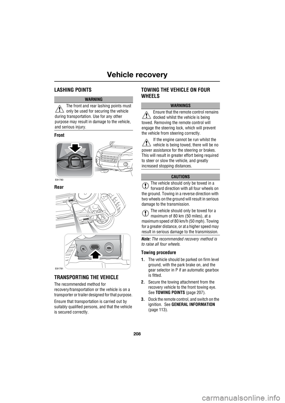
LASHING POINTS
Front
Rear
TRANSPORTING THE VEHICLE
The recommended method for
recovery/transportation or the vehicle is on a
transporter or trailer de signed for that purpose.
Ensure that transporta tion is carried out by
suitably qualified persons , and that the vehicle
is secured correctly.
TOWING THE VEHICLE ON FOUR
WHEELS
Note: The recommended recovery method is
to raise all four wheels.
Towing procedure
1. The vehicle should be parked on firm level
ground, with the park brake on, and the
gear selector in P if an automatic gearbox
is fitted.
2. Secure the towing attachment from the
recovery vehicle to the front towing eye.
See TOWING POINTS (page 207).
3. Dock the remote control, and switch on the
ignition. See GENERAL INFORMATION
(page 113).
WARNING
The front and rear lashing points must
only be used for securing the vehicle
during transportation. Use for any other
purpose may result in da mage to the vehicle,
and serious injury.
E81780
E81781
WARNINGS
Ensure that the remote control remains
docked whilst the vehicle is being
towed. Removing the remote control will
engage the steering lo ck, which will prevent
the vehicle from steering correctly.
If the engine cannot be run whilst the
vehicle is being towed, there will be no
power assistance for the steering or brakes.
This will result in grea ter effort being required
to steer or slow the vehicle, and greatly
increased stopping distances.
CAUTIONS
The vehicle should only be towed in a
forward direction with all four wheels on
the ground. Towing in a reverse direction with
two wheels on the ground will result in serious
damage to the transmission.
The vehicle should only be towed for a
maximum of 80 km (50 miles), at a
maximum speed of 80 k m/h (50 mph). Towing
for a greater distance, or at a higher speed may
result in serious dama ge to the transmission.
Page 2970 of 3229
Auxiliary input (AUX IN) socket
250
L
Auxiliary input (AUX IN) socketAUXILIARY INPUT (AUX IN) SOCKET
AUX (Auxiliary Input) mode allows extra
equipment to be connect ed to the vehicle's
audio system. Items such as a personal stereo,
MP3 player, hand-held n avigation unit etc., can
be plugged in to the vehicle's audio system.
Note: The volume levels and sound quality
available from devices connected to the
auxiliary inputs may vary widely. If the
connected audio device is equipped with a line
out socket as well as a headphone socket, the
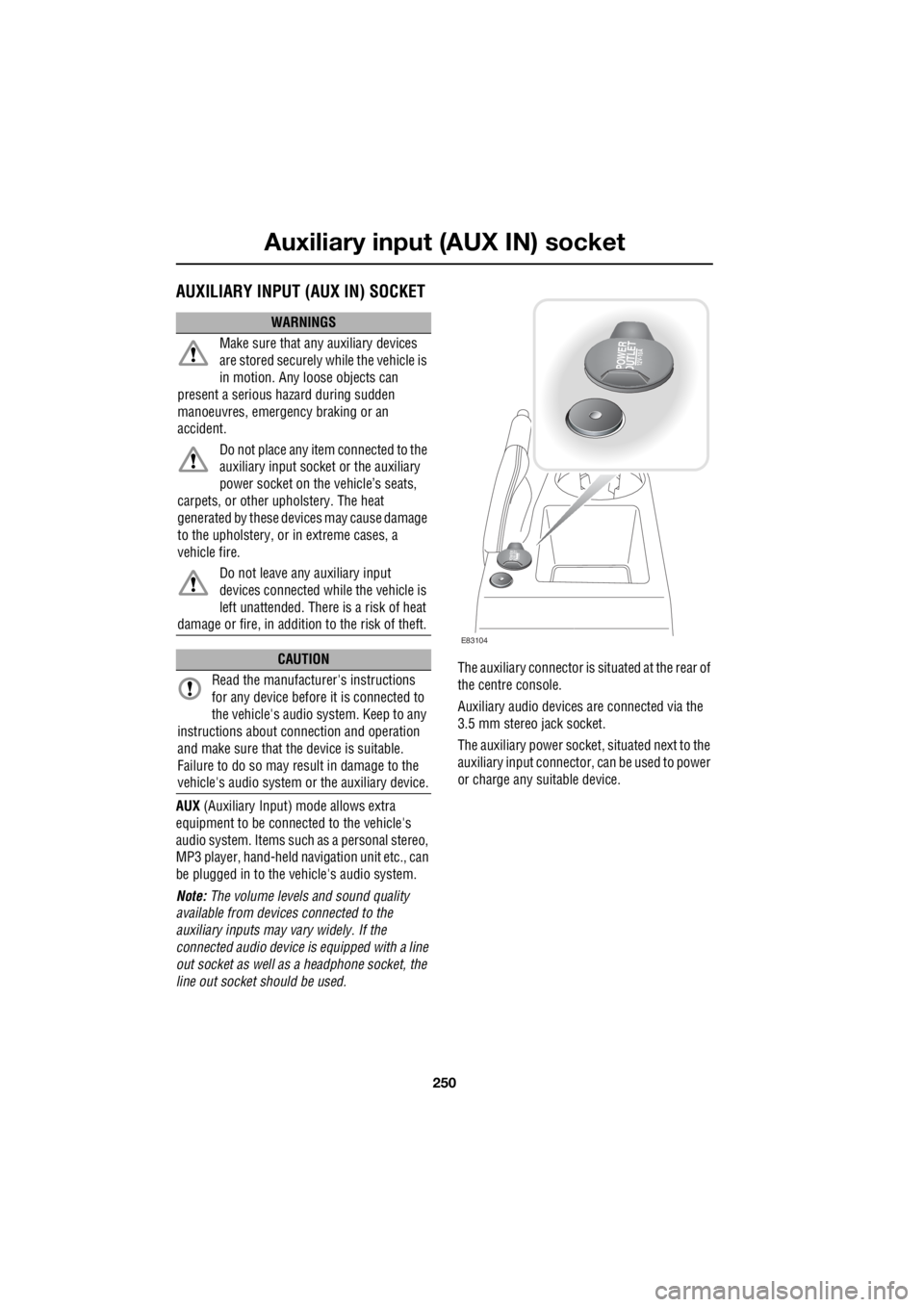
line out socket should be used. The auxiliary connector is
situated at the rear of
the centre console.
Auxiliary audio devices are connected via the
3.5 mm stereo jack socket.
The auxiliary power socket , situated next to the
auxiliary input connector, can be used to power
or charge any suitable device.
WARNINGS
Make sure that any auxiliary devices
are stored securely while the vehicle is
in motion. Any loose objects can
present a serious hazard during sudden
manoeuvres, emergency braking or an
accident.
Do not place any item connected to the
auxiliary input socket or the auxiliary
power socket on the vehicle’s seats,
carpets, or other upholstery. The heat
generated by these devi ces may cause damage
to the upholstery, or in extreme cases, a
vehicle fire.
Do not leave any auxiliary input
devices connected while the vehicle is
left unattended. There is a risk of heat
damage or fire, in additi on to the risk of theft.
CAUTION
Read the manufacturer's instructions
for any device before it is connected to
the vehicle's audio system. Keep to any
instructions about c onnection and operation
and make sure that the device is suitable.
Failure to do so may result in damage to the
vehicle's audio system or the auxiliary device.
POWER
OUTLET12V-10A
POWER
OUTLET12 V -1
0 A
E83104
Page 2974 of 3229
Telephone
254
L
TelephoneGENERAL INFORMATION
Note: The vehicle tele phone system is
designed to function with a wide variety of
Bluetooth telephones. As these telephones
have a wide range of audio and echo
performance characteristics, it may take a few
seconds for the vehicl e telephone system to
adapt and deliver optimum audio performance.
It may be necessary to reduce the in-vehicle
volume slightly to fully optimise audio
performance and reduce echo. Note:
The vehicle's Bluetooth telephone
system can be used with an appropriate
Bluetooth-equipped mobile telephone.
Note: Please refer to your Land Rover
Dealer/Authorised Repairer for a list of
compatible telephones.
Telephone networks
The Telephone netw ork standard allows you to
use your telephone in many countries.
However, telephone reception may be poor or
unavailable in remote re gions. This may be due
to the inadequate power of the transmitter,
which results in a weak signal or incomplete
coverage.
WARNINGS
Using the telephone ne ar the car: do not
telephone inside a garage or near an
open car bonnet. The air may contain fuel
vapours and the tele phone could produce
sparks and start a fire.
Unusual ambient conditions: Switch off
the telephone in areas where high
explosives are being used. High frequency
remote controls could be interfered with and
cause an explosion. Switch off your telephone
in areas with a high explosion risk. This
includes filling stations, fuel storage areas or
chemical factories, as well as places where the
air contains fuel vapour, chemicals or metal
dust. The telephone might possibly produce
sparks and cause a fire or explosion.
Medical equipment: The functioning of
cardiac pacemakers or hearing aids
may be impaired when the phone is in use.
Check with a doctor or manufacturer whether
any such devices you or your passengers are
using are sufficiently protected against
high-frequency energy.
Always stow your mobile phone
securely. In an accident loose items can
cause injury.
Page 3038 of 3229
414-01 BATTERY, MOUNTING AND CABLES
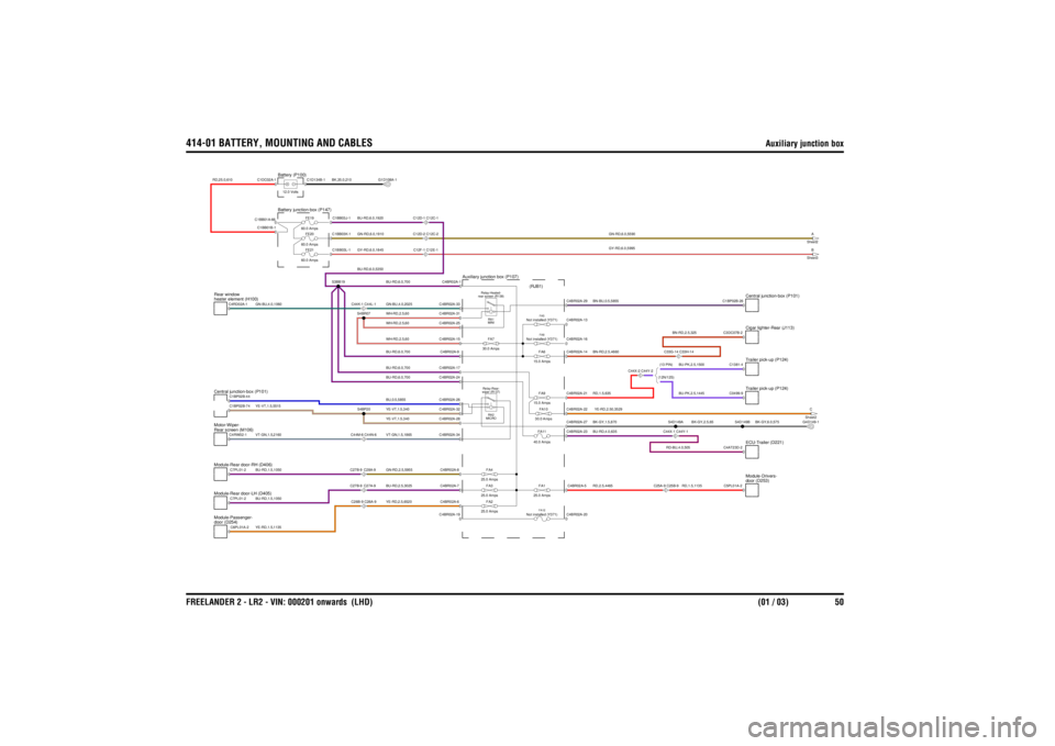
Auxiliary junction box
FREELANDER 2 - LR2 - VIN: 000201 onwards (LHD) (01 / 03) 50
Auxiliary junction box
GY-RD,6.0,5995GN-RD,6.0,5590
BU-RD,1.5,1050YE-RD,1.5,1135
YE-RD,2.5,6520BU-RD,2.5,3025BU-RD,6.0,700WH-RD,2.5,60BU-RD,6.0,700BU-RD,6.0,700
BU-RD,1.5,1050VT-GN,1.5,2160YE-VT,1.5,5515
BU,0.5,5855VT-GN,1.5,1865YE-VT,1.5,340YE-VT,1.5,340GN-RD,2.5,5955WH-RD,2.5,60WH-RD,2.5,60
BU-RD,6.0,5350
GN-BU,4.0,1060
GY-RD,6.0,1845GN-RD,6.0,1910BU-RD,6.0,1920
BK,35.0,210
RD,25.0,610
BU-RD,6.0,700GN-BU,4.0,2025
RD,2.5,4465
RD,1.5,1135
BU-RD,4.0,635YE-RD,2.50,3529BK-GY,1.5,870BN-RD,2.5,4660
RD-BU,4.0,505
RD,1.5,635
BK-GY,2.5,65
BK-GY,6.0,575
BN-RD,2.5,325BU-PK,2.5,1500
(13 PIN)BU-PK,2.5,1445
(12N/12S)
BN-BU,0.5,5855
FA3
25.0 AmpsFA2
25.0 AmpsFA4
25.0 Amps
Not installed (Y371)
FA5FA6
15.0 Amps
Not installed (Y371)
FA8
FE21
60.0 AmpsFE20
60.0 AmpsFE19
60.0 Amps
FA9
15.0 Amps
wiper (R137) Relay-Rear-
RA2
MICROFA7
30.0 Amps
rear screen (R138) Relay-Heated-
RA1
MINI
Auxiliary junction box (P107)
(RJB1)
Module-Rear door-RH (D406)Module-Rear door-LH (D405)door (D254)
Module-Passenger-
C26B-9 C26A-9C27B-9
C27A-9
Central junction-box (P101)Rear screen (M106)
Motor-Wiper-
C44M-6 C44N-6C27B-9
C28A-9
Battery junction-box (P147)
heater element (H100)
Rear window
Battery (P100)12.0 Volts
C12D-2 C12C-2C12F-1 C12E-1
C44K-1 C44L-1
C12D-1 C12C-1
door (D253)
Module-Drivers-
FA1
25.0 Amps
C25A-9 C25B-9
Not installed (Y371)
FA12
A
Sheet2B
Sheet3C
Sheet2
FA11
40.0 AmpsFA10
30.0 Amps
C44X-2 C44Y-2
Trailer pick-up (P124)
C44X-1 C44Y-1
ECU-Trailer (D221)
C33G-14 C33H-14
Trailer pick-up (P124)Cigar lighter-Rear (J113)Central junction-box (P101)
C6PL01A-2C7PL01-2
C4BR02A-6C4BR02A-7C4BR02A-19C4BR02A-31
S4BR07
C1BP02B-44C4RW02-1C7PL01-2C1BP02B-74
C4BR02A-26
S4BP20
C4BR02A-34C4BR02A-8C4BR02A-32C4BR02A-28C4BR02A-24C4BR02A-17C4BR02A-15C4BR02A-9C4BR02A-25
C1BB03L-1C1BB03K-1C1BB03J-1S3BB19
C4RD02A-1
C1BB01A-66C1BB01B-1C1DC02A-1
C1D134B-1
C4BR02A-33C4BR02A-1
G1D108A-1
C4BR02A-5C4BR02A-20
C5PL01A-2
G4D149-1
C4BR02A-21C4BR02A-23C4BR02A-22C4BR02A-27C4BR02A-14C4BR02A-13C4BR02A-16
C0499-9C4AT23D-2
S4D149B
S4D149A
C3DC07B-2C1381-4
C4BR02A-29
C1BP02B-26