Page 1573 of 3229
Remove t he nut and bol t securi ng the fuel tank
fill er pipe t o t he body.
T orque: 10 Nm Loosen t he fuel t ank fi ll er pi pe lower bracket .
T orque: 10 Nm Loosen t he cli p and dis connect the fuel fi ller
hos e from t he fuel t ank. Loosen t he cli p and dis connect fuel fi ll er pi pe
vent hos e. 6.
T orque:
10 Nm 7.
Installation To i nst all , revers e t he removal procedure.
1.
Page 1582 of 3229
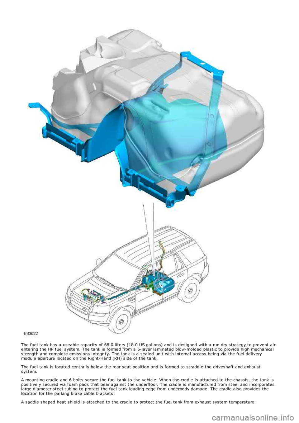
The fuel t ank has a useable capaci ty of 68.0 li ters (18.0 US gal lons) and i s des igned wit h a run dry s trat egy t o prevent ai rentering t he HP fuel s ys tem. The t ank is formed from a 6-layer lami nat ed blow-molded pl as t ic t o provi de high mechani cals trengt h and complet e emis s ions i ntegri ty. The t ank is a sealed uni t wit h i nt ernal acces s being via the fuel del iverymodule apert ure locat ed on t he Right -Hand (RH) s ide of t he tank.
The fuel t ank is l ocat ed cent rall y below the rear s eat posi ti on and is formed to s traddl e the drives haft and exhaus ts ys t em.
A mount ing cradl e and 6 bolt s s ecure t he fuel tank t o t he vehi cle. W hen t he cradle is at tached to the chass i s, t he t ank isposi ti vel y s ecured via foam pads t hat bear agai nst t he underfl oor. The cradle is manufact ured from st eel and incorporateslarge diamet er s t eel t ubing t o prot ect t he fuel t ank leading edge from underbody damage. The cradle al so provides thelocati on for t he parking brake cable bracket s .
A s addle s haped heat s hiel d is at t ached t o t he cradle t o prot ect the fuel t ank from exhaust s ys tem temperature.
Page 1584 of 3229
Int ernal mounti ng bracketFuel deli very module and cross over tube2 MAPPS t ype fuel s ender unit sBreat her valve.
Internal Mounting Bracket
The int ernal mount ing bracket i s molded i nto t he t ank cas ing and provi des the locat ion for the breather val ve, andcros sover tube as s embly.
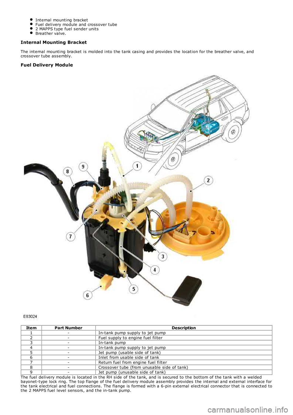
Fuel Delivery Module
ItemPart NumberDescription
1-In-t ank pump supply to jet pump
2-Fuel s upply t o engine fuel fil ter3-In-t ank pump
4-In-t ank pump supply to jet pump
5-Jet pump (us able s ide of t ank)6-Inl et from us able s ide of t ank
7-Return fuel from engi ne fuel fi lt er
8-Cros s over t ube (from unus able si de of tank)9-Jet pump (unus abl e s ide of t ank)
The fuel deli very module i s located in t he RH s i de of the t ank, and i s s ecured to the bot tom of the t ank wit h a weldedbayonet-t ype lock ri ng. The t op flange of the fuel del ivery module ass embly provides t he int ernal and ext ernal interface fort he tank elect rical and fuel connecti ons . The flange is formed wit h a 6-pin ext ernal el ect ri cal connector t hat is connect ed tot he 2 MAPPS fuel l evel s ens ors , and t he in-tank pump.
Page 1585 of 3229
The fuel deli very module flange i s s eal ed to the t ank wit h an O-ring and s ecured wi th a locki ng ring.
The lower part of t he fuel deli very module forms the fuel del ivery pot , and provides the locat ion for the in-t ank pump andt he 2 jet pumps . The delivery pot provi des a cons t ant res ervoir of fuel for t he engine drawn fuel supply. The engine fuels uppl y and ret urn l ines are immers ed in the del ivery pot .
The delivery pot is mai ntained full by t he 2 jet pumps . The i n-t ank pump draws fuel from wit hin the fuel deli very pot andforces the fuel t hrough t he 2 jet pumps . The flow of fuel t hrough each jet pump creat es a venturi effect t hat draws fuelfrom bot h s ides of t he fuel tank i nto the fuel deli very pot. Surpl us fuel entering the fuel deli very pot overflows into theus abl e s ide of t he fuel t ank.
A valve i s l ocated in t he l ower (usabl e tank s i de) jet pump s uppl y ori fi ce. The valve i s open when the i n-t ank pump isenergized and t he lower jet pump is s upplying fuel i nto the fuel del ivery pot . The val ve wil l cl os e when the i n-t ank pump isde-energized t o prevent fuel drai ni ng from the fuel del ivery pot .
The in-tank pump is energized by t he fuel pump relay l ocat ed in the Cent ral Juncti on Box (CJB). The Engine Cont rol Module(ECM) energi zes the fuel pump relay at al l ti mes when t he ignit ion i s in power modes 4 (Acces s ory) t o 9 (Engi ne crank).For addit ional informat ion, refer t o: Electroni c Engi ne Controls - 2.2L Dies el (303-14 El ect ronic Engine Cont rols - 2.2LDies el, Des cript ion and Operat ion).
A modi fi ed fuel delivery modul e i s ins tal led for col d climat e market vehicl es that feat ure a fuel fi red boos ter heater andauxi li ary fuel pump. The modified fuel del ivery modul e incorporat es a s eparate fuel supply line that connects t o anauxi li ary fuel pump, mounted on the ext erior RH si de of the tank. An addi ti onal fuel l ine connects the auxil iary fuel pumpt o the fuel fi red boos ter heat er.For addit ional informat ion, refer t o: Fuel Fired Boost er Heat er (412-02B Auxi liary Cli mate Cont rol , Des cri pti on andOperat ion).
Fuel Sender Units
The 2 MAPPS fuel s ender uni ts are located on eit her s ide of t he s addl e s haped tank, and connect t o t he int ernal elect ricalconnecti ons on the fuel del ivery modul e fl ange. Each s ens or provides an elect rical signal t o t he CJB t hat i s proport ionatet o the fuel level i n each s ide of t he tank.
The act ual fuel level i n t he t ank i s calculated by the CJB and t rans mit t ed via t he medium s peed Cont roll er Area Net work(CAN) bus t o t he ins t rument clus ter.
A warning l amp is incorporat ed in t he i ns t rument clus ter and wi ll il lumi nat e when t he fuel l evel is at, or below apredetermined l evel . On vehi cles wi th a high-l ine i nst rument clus ter, a mes s age is di spl ayed and a chi me i s s ounded t oinform the driver to refuel .
For addit ional informat ion, refer t o:
Ins trument Clus ter (413-01 Ins t rument Clus t er, Descripti on and Operat ion),Informat ion and Mes s age Cent er (413-08 Informati on and Mes sage Cent er, Descripti on and Operat ion).
Fuel Tank Breather Valve
The breat her valve i s located i n t he fuel t ank and is connected to the fuel deli very module fl ange vi a an i nt ernal breatherhose. The breat her valve al lows ai r to es cape and ent er the fuel tank t o compens at e for t he changing vol ume wit hin thet ank.
FUEL TANK FILLER
Page 1588 of 3229
prot ect ion t ray is s ecured wit h i ntegral cli ps on the ins ide of t he tray t o s tuds along t he underfl oor.
CAUTION: The fuel l ine quick-fit t ype connect or is a new des ign connector i ns t alled to the TD4 vehicle. Duringmaint enance procedures t he quick-fi t t ype connect or must be releas ed and connected correct ly to prevent fuel l eakage.Us e t he correct met hod det ailed in t he rel evant s ect ion of t he Servi ce Repair Manual (SRP) t o rel eas e and connect t heconnector. Incorrect operati on of the qui ck-fi t type connector wi ll res ult in damage t o t he connector and caus e fuelleakage.
The quick-fit t ype fuel connect or is not a s elf s eali ng connector, and will not prevent fuel fl ow when dis connected.
The fuel s uppl y and ret urn lines are connected at each end wit h a qui ck-fi t type connect or. The connector is nots elf-s eal ing and will not prevent fuel fl ow when t he fuel li ne is separat ed.
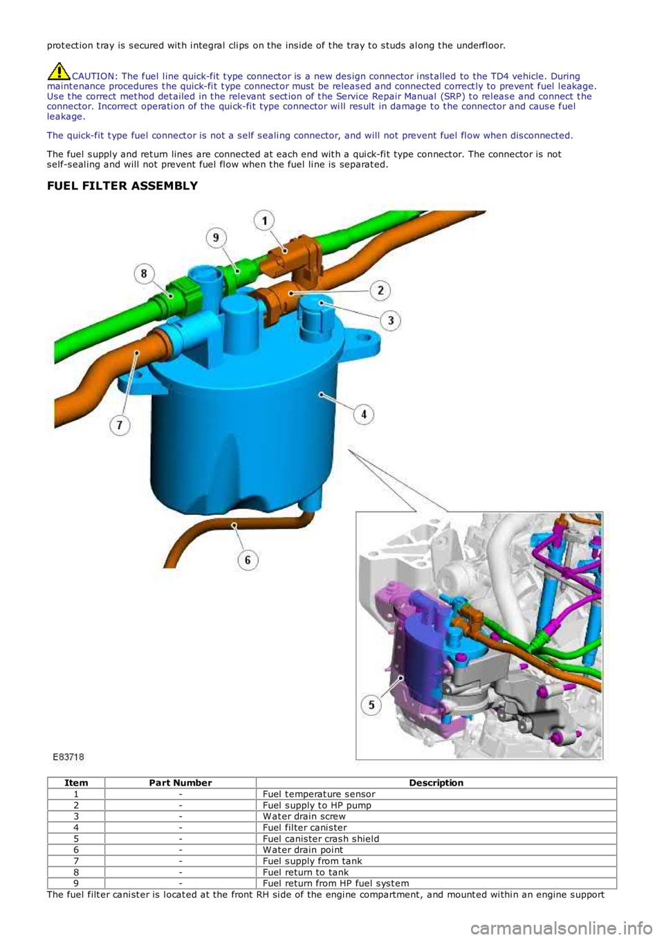
FUEL FILTER ASSEMBLY
ItemPart NumberDescription
1-Fuel t emperat ure s ensor
2-Fuel s upply t o HP pump3-W at er drain screw
4-Fuel fil ter cani s ter
5-Fuel canis ter cras h s hiel d6-W at er drain poi nt
7-Fuel s upply from tank
8-Fuel return to tank9-Fuel return from HP fuel s ys t em
The fuel filt er cani st er is l ocat ed at the front RH si de of the engi ne compartment , and mount ed wi thi n an engine s upport
Page 1606 of 3229
Remove t he nut and bol t securi ng the fuel tank
fill er pipe t o t he body.
T orque: 10 Nm Loosen t he fuel t ank fi ll er pi pe lower bracket .
T orque: 10 Nm Loosen t he cli p and dis connect the fuel fi ller
hos e from t he fuel t ank. Loosen t he cli p and dis connect fuel fi ll er pi pe
vent hos e. 6.
T orque:
10 Nm 7.
Installation To i nst all , revers e t he removal procedure.
1.
Page 1634 of 3229
OVERVIEW
The air dis t ri but ion and fil tering s ys tem cont rols the di st ributi on and qual it y of air s uppl ied i nto t he front and rear of t hecabi n. The sys tem cons is t s of:
Air ductsAir regi s ters and vent sA cabin ai r fi lt er.
AIR DUCTS
The air ducts di st ri bute ai r from t he heater as sembl y to the various regi st ers and vents in t he i ns t rument panel and t o t herear of t he vehi cl e.
The face l evel /s ide window duct and t he wi nds hiel d duct form part of t he ins trument panel as sembl y.
Each front footwell duct is a s nap fit into the s i de of the heater as s embly and s ecured t o the cross car beam by a s ingles crew. The front footwel l ducts als o provide a locati on for t he foot well lamps .
The rear cabi n ducts are als o a snap fit i nto the heater as s embly. Each duct runs underneath t he carpet and is secured t ot he fl oor of t he vehi cl e by a si ngl e s crew l ocat ed beneat h t he front seat .
AIR REGISTERS AND VENTS
The air regi s ters allow the vehicle occupant s t o cont rol t he fl ow and di recti on of ai r from t he air ducts . The ins t rumentpanel contains 4 air regi st ers ; 1 mount ed on eit her end of t he i ns t rument panel and 2 mount ed central ly.
The air vents are fixed outl et s . The ins trument panel cont ains 4 ai r vent s ; 1 mounted on ei ther end of t he ins trumentpanel and 2 mount ed along t he t op edge, below the wi ndshi el d.
CABIN AIR FILTER
The cabi n air fil ter is locat ed behind t he RH s i de of the i nst rument panel and is housed wit hin t he heater as sembl y. Thefi lt er removes odors and fine part icl es , i ncludi ng pol len, from t he air ent ering the heater as s embly.
Page 1662 of 3229
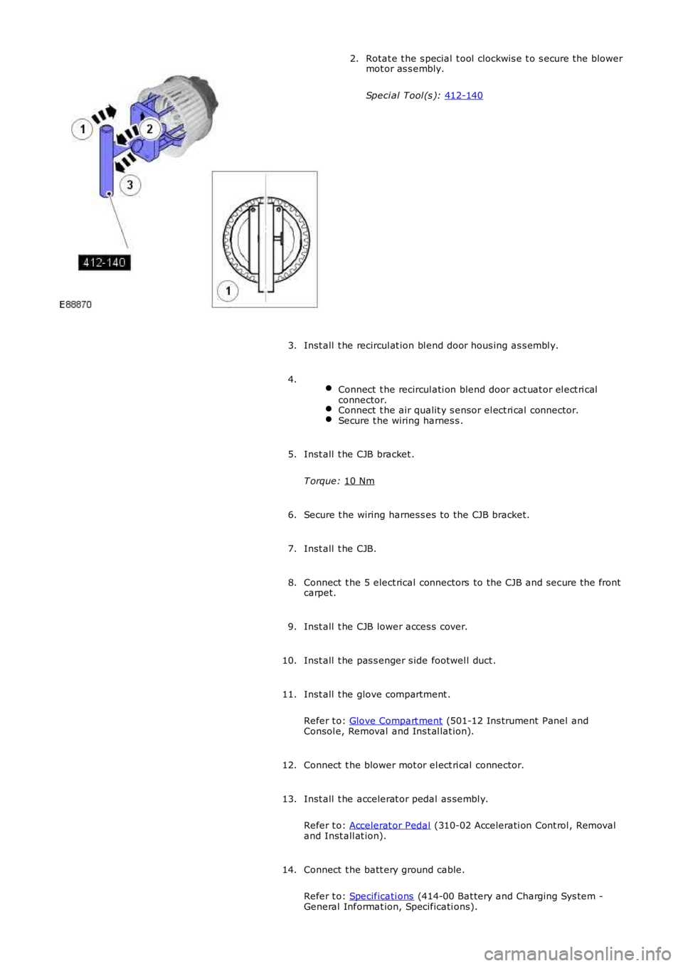
Rotat e t he s pecial t ool clockwis e t o s ecure t he blower
mot or as s embly.
Speci al Tool (s ): 412-140 2.
Inst all t he recircul at ion bl end door hous ing as s embl y.
3.
Connect t he recircul ati on blend door act uat or el ect ri cal
connector. Connect t he air qualit y s ensor el ect ri cal connector.
Secure t he wiring harnes s .4.
Inst all t he CJB bracket .
T orque: 10 Nm 5.
Secure t he wiring harnes s es to the CJB bracket.
6.
Inst all t he CJB.
7.
Connect t he 5 elect rical connectors to the CJB and s ecure t he front
carpet.
8.
Inst all t he CJB lower acces s cover.
9.
Inst all t he pas s enger s ide footwel l duct .
10.
Inst all t he glove compartment .
Refer t o: Glove Compart ment (501-12 Ins trument Panel and
Consol e, Removal and Ins t al lat ion).
11.
Connect t he blower mot or el ect ri cal connector.
12.
Inst all t he accelerat or pedal as sembl y.
Refer t o: Accelerat or Pedal (310-02 Accelerati on Cont rol , Removal
and Inst all at ion).
13.
Connect t he batt ery ground cable.
Refer t o: Specificati ons (414-00 Bat tery and Charging Sys tem -
General Informat ion, Specificati ons).
14.