2006 LAND ROVER FRELANDER 2 fuel pump
[x] Cancel search: fuel pumpPage 1581 of 3229
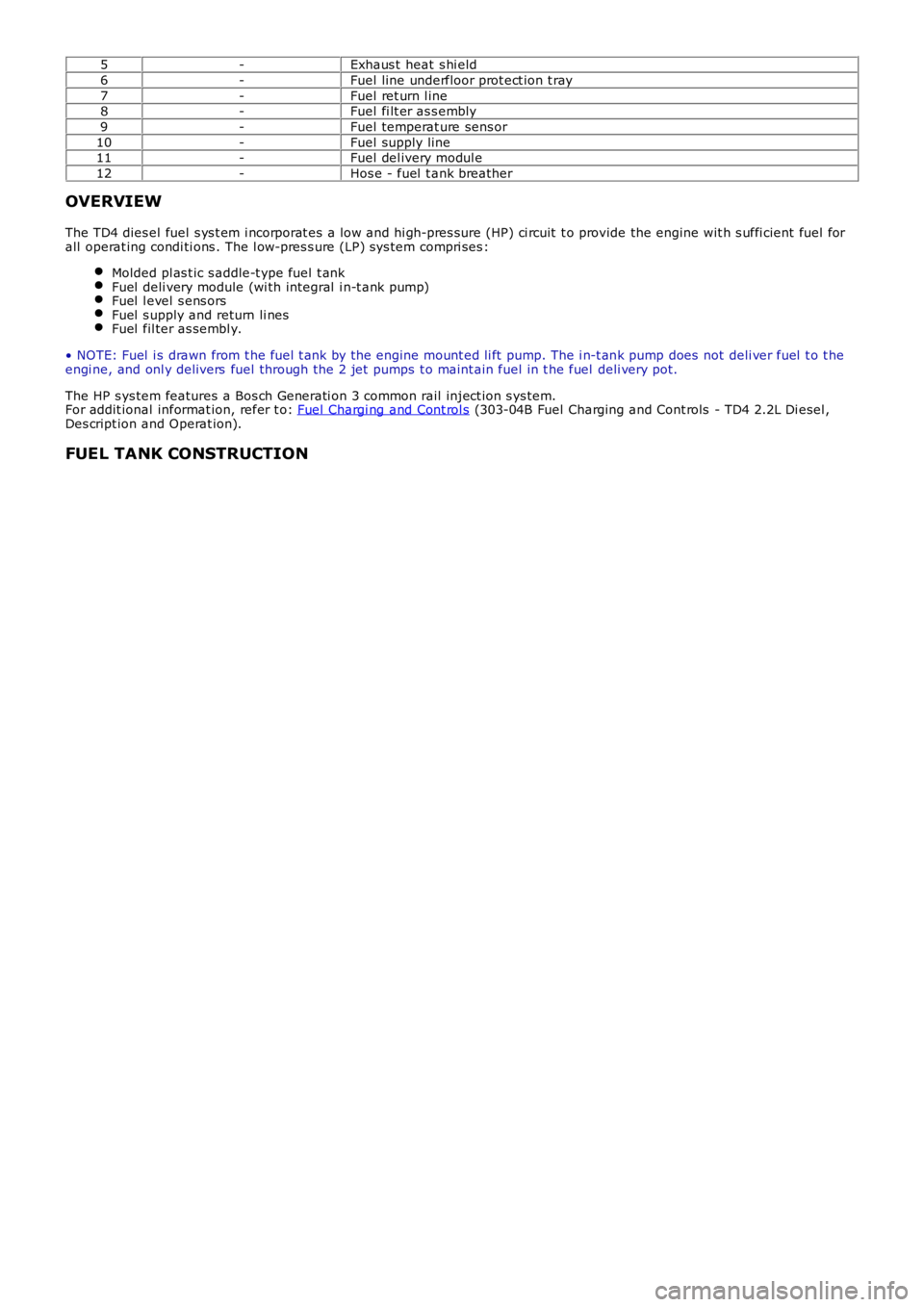
5-Exhaus t heat s hi eld
6-Fuel line underfloor prot ect ion t ray
7-Fuel ret urn l ine8-Fuel fi lt er as s embly
9-Fuel temperat ure sens or
10-Fuel supply line11-Fuel del ivery modul e
12-Hos e - fuel t ank breather
OVERVIEW
The TD4 dies el fuel s ys t em i ncorporat es a l ow and hi gh-pres sure (HP) ci rcuit t o provide the engine wit h s uffi cient fuel forall operat ing condi ti ons . The l ow-pres s ure (LP) sys tem compri ses :
Molded pl as t ic s addle-t ype fuel t ankFuel deli very module (wi th integral i n-t ank pump)Fuel l evel s ens orsFuel s upply and return li nesFuel fil ter as sembl y.
• NOTE: Fuel i s drawn from t he fuel t ank by the engine mount ed li ft pump. The i n-t ank pump does not deli ver fuel t o t heengi ne, and onl y delivers fuel through the 2 jet pumps t o maint ain fuel in t he fuel deli very pot.
The HP s ys tem features a Bos ch Generati on 3 common rail inject ion s ys tem.For addit ional informat ion, refer t o: Fuel Chargi ng and Cont rol s (303-04B Fuel Charging and Cont rols - TD4 2.2L Di esel ,Des cript ion and Operat ion).
FUEL TANK CONSTRUCTION
Page 1584 of 3229
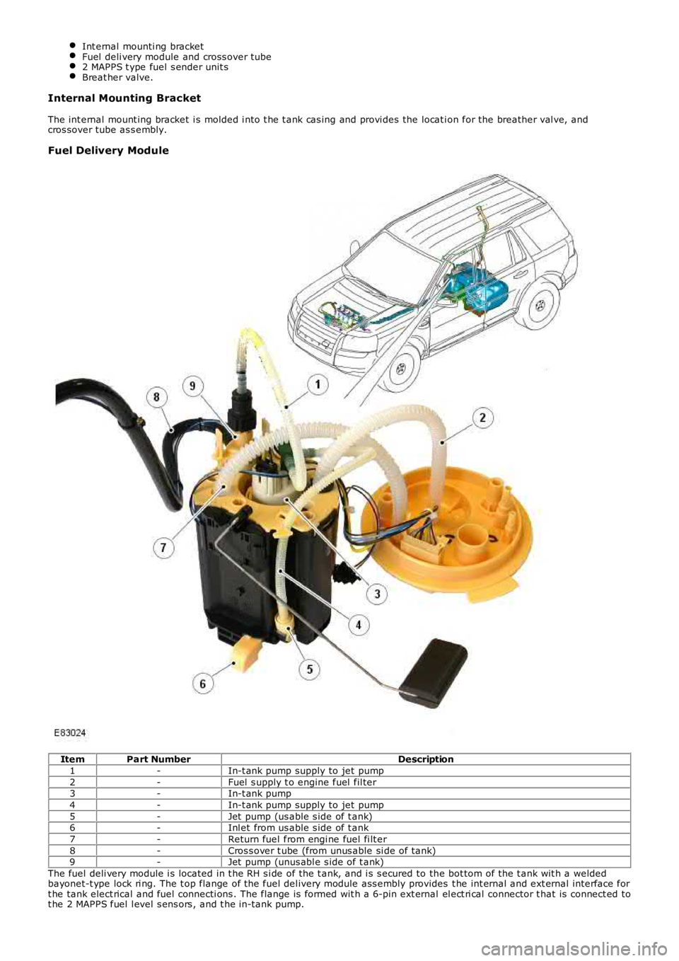
Int ernal mounti ng bracketFuel deli very module and cross over tube2 MAPPS t ype fuel s ender unit sBreat her valve.
Internal Mounting Bracket
The int ernal mount ing bracket i s molded i nto t he t ank cas ing and provi des the locat ion for the breather val ve, andcros sover tube as s embly.
Fuel Delivery Module
ItemPart NumberDescription
1-In-t ank pump supply to jet pump
2-Fuel s upply t o engine fuel fil ter3-In-t ank pump
4-In-t ank pump supply to jet pump
5-Jet pump (us able s ide of t ank)6-Inl et from us able s ide of t ank
7-Return fuel from engi ne fuel fi lt er
8-Cros s over t ube (from unus able si de of tank)9-Jet pump (unus abl e s ide of t ank)
The fuel deli very module i s located in t he RH s i de of the t ank, and i s s ecured to the bot tom of the t ank wit h a weldedbayonet-t ype lock ri ng. The t op flange of the fuel del ivery module ass embly provides t he int ernal and ext ernal interface fort he tank elect rical and fuel connecti ons . The flange is formed wit h a 6-pin ext ernal el ect ri cal connector t hat is connect ed tot he 2 MAPPS fuel l evel s ens ors , and t he in-tank pump.
Page 1585 of 3229
The fuel deli very module flange i s s eal ed to the t ank wit h an O-ring and s ecured wi th a locki ng ring.
The lower part of t he fuel deli very module forms the fuel del ivery pot , and provides the locat ion for the in-t ank pump andt he 2 jet pumps . The delivery pot provi des a cons t ant res ervoir of fuel for t he engine drawn fuel supply. The engine fuels uppl y and ret urn l ines are immers ed in the del ivery pot .
The delivery pot is mai ntained full by t he 2 jet pumps . The i n-t ank pump draws fuel from wit hin the fuel deli very pot andforces the fuel t hrough t he 2 jet pumps . The flow of fuel t hrough each jet pump creat es a venturi effect t hat draws fuelfrom bot h s ides of t he fuel tank i nto the fuel deli very pot. Surpl us fuel entering the fuel deli very pot overflows into theus abl e s ide of t he fuel t ank.
A valve i s l ocated in t he l ower (usabl e tank s i de) jet pump s uppl y ori fi ce. The valve i s open when the i n-t ank pump isenergized and t he lower jet pump is s upplying fuel i nto the fuel del ivery pot . The val ve wil l cl os e when the i n-t ank pump isde-energized t o prevent fuel drai ni ng from the fuel del ivery pot .
The in-tank pump is energized by t he fuel pump relay l ocat ed in the Cent ral Juncti on Box (CJB). The Engine Cont rol Module(ECM) energi zes the fuel pump relay at al l ti mes when t he ignit ion i s in power modes 4 (Acces s ory) t o 9 (Engi ne crank).For addit ional informat ion, refer t o: Electroni c Engi ne Controls - 2.2L Dies el (303-14 El ect ronic Engine Cont rols - 2.2LDies el, Des cript ion and Operat ion).
A modi fi ed fuel delivery modul e i s ins tal led for col d climat e market vehicl es that feat ure a fuel fi red boos ter heater andauxi li ary fuel pump. The modified fuel del ivery modul e incorporat es a s eparate fuel supply line that connects t o anauxi li ary fuel pump, mounted on the ext erior RH si de of the tank. An addi ti onal fuel l ine connects the auxil iary fuel pumpt o the fuel fi red boos ter heat er.For addit ional informat ion, refer t o: Fuel Fired Boost er Heat er (412-02B Auxi liary Cli mate Cont rol , Des cri pti on andOperat ion).
Fuel Sender Units
The 2 MAPPS fuel s ender uni ts are located on eit her s ide of t he s addl e s haped tank, and connect t o t he int ernal elect ricalconnecti ons on the fuel del ivery modul e fl ange. Each s ens or provides an elect rical signal t o t he CJB t hat i s proport ionatet o the fuel level i n each s ide of t he tank.
The act ual fuel level i n t he t ank i s calculated by the CJB and t rans mit t ed via t he medium s peed Cont roll er Area Net work(CAN) bus t o t he ins t rument clus ter.
A warning l amp is incorporat ed in t he i ns t rument clus ter and wi ll il lumi nat e when t he fuel l evel is at, or below apredetermined l evel . On vehi cles wi th a high-l ine i nst rument clus ter, a mes s age is di spl ayed and a chi me i s s ounded t oinform the driver to refuel .
For addit ional informat ion, refer t o:
Ins trument Clus ter (413-01 Ins t rument Clus t er, Descripti on and Operat ion),Informat ion and Mes s age Cent er (413-08 Informati on and Mes sage Cent er, Descripti on and Operat ion).
Fuel Tank Breather Valve
The breat her valve i s located i n t he fuel t ank and is connected to the fuel deli very module fl ange vi a an i nt ernal breatherhose. The breat her valve al lows ai r to es cape and ent er the fuel tank t o compens at e for t he changing vol ume wit hin thet ank.
FUEL TANK FILLER
Page 1588 of 3229
prot ect ion t ray is s ecured wit h i ntegral cli ps on the ins ide of t he tray t o s tuds along t he underfl oor.
CAUTION: The fuel l ine quick-fit t ype connect or is a new des ign connector i ns t alled to the TD4 vehicle. Duringmaint enance procedures t he quick-fi t t ype connect or must be releas ed and connected correct ly to prevent fuel l eakage.Us e t he correct met hod det ailed in t he rel evant s ect ion of t he Servi ce Repair Manual (SRP) t o rel eas e and connect t heconnector. Incorrect operati on of the qui ck-fi t type connector wi ll res ult in damage t o t he connector and caus e fuelleakage.
The quick-fit t ype fuel connect or is not a s elf s eali ng connector, and will not prevent fuel fl ow when dis connected.
The fuel s uppl y and ret urn lines are connected at each end wit h a qui ck-fi t type connect or. The connector is nots elf-s eal ing and will not prevent fuel fl ow when t he fuel li ne is separat ed.
FUEL FILTER ASSEMBLY
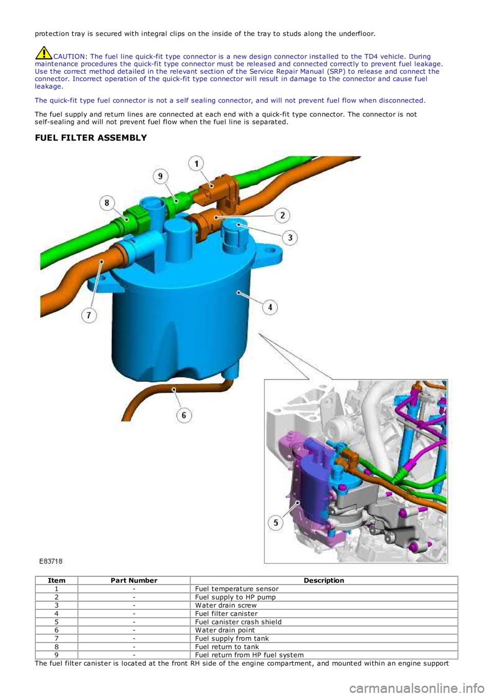
ItemPart NumberDescription
1-Fuel t emperat ure s ensor
2-Fuel s upply t o HP pump3-W at er drain screw
4-Fuel fil ter cani s ter
5-Fuel canis ter cras h s hiel d6-W at er drain poi nt
7-Fuel s upply from tank
8-Fuel return to tank9-Fuel return from HP fuel s ys t em
The fuel filt er cani st er is l ocat ed at the front RH si de of the engi ne compartment , and mount ed wi thi n an engine s upport
Page 1591 of 3229
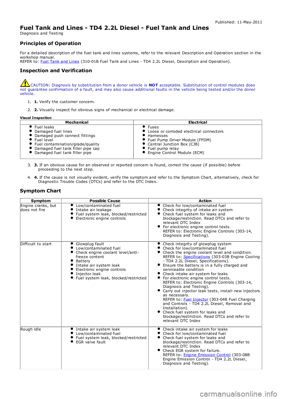
Publi s hed: 11-May-2011
Fuel Tank and Lines - TD4 2.2L Diesel - Fuel Tank and Lines
Diagnosi s and Tes ti ng
Principles of Operation
For a detail ed descripti on of the fuel tank and l ines s ys t ems , refer t o t he rel evant Des cript ion and Operat ion s ecti on in the
works hop manual .
REFER to: Fuel Tank and Lines (310-01B Fuel Tank and Lines - TD4 2.2L Dies el, Des cript ion and Operat ion).
Inspection and Verification CAUTION: Di agnos is by s ubs ti tut ion from a donor vehicle is
NO T acceptabl e. Subs ti tut ion of cont rol modules does
not guarant ee confirmat ion of a faul t, and may als o caus e addit ional fault s i n t he v ehi cl e being t est ed and/or t he donor
vehi cl e.
1. Verify t he cus t omer concern.
1.
2. Vis ually ins pect for obvious s igns of mechani cal or electrical damage.
2.
Visual Inspection Mechanical Electrical
Fuel l eaks Damaged fuel l ines
Damaged push connect fit t ings
Fuel l evel
Fuel contami nati on/grade/quali ty
Damaged fuel t ank fi ller pipe cap
Damaged fuel t ank fi ller pipe Fuses
Loos e or corroded elect rical connect ors
Harnes s es
Fuel Pump Dri ver Module (FPDM)
Central Junct ion Box (CJB)
Fuel pump relay
Engine Control Modul e (ECM)
3.
If an obvious cause for an obs erved or report ed concern is found, correct t he caus e (if pos s ible) before
proceeding t o t he next s t ep.
3.
4. If t he caus e is not vis ually evi dent , verify t he sympt om and refer t o t he Sympt om Ch art, al ternat ively, check for
Di agnos ti c Trouble Codes (DTCs) and refer t o t he DTC Index.
4.
Symptom Chart Symptom Possible Cause Action
Engine cranks , but
does not fi re Low/contaminated fuel Intake air l eakage
Fuel sys tem leak, blocked/res tricted
El ect ronic engine controls Check for l ow/contami nat ed fuel
Check int egrit y of i nt ake air s yst em
Check fuel s yst em for leaks and
bl ockage/res t ri ct ion. Read DTCs and refer to
relevant DTC Index For electronic engine control t es ts .
REFER t o: Electroni c Engi ne Control s (303-14,
Diagnos is and Tes t ing). Di fficul t t o s tart
Gl owpl ug faul t Low/contaminated fuel
Check engi ne cool ant l evel /anti -
freeze cont ent Bat tery
Intake air s ys tem leak
El ect ronic engine controls
Injector l eak
Fuel sys tem leak, blocked/res tricted Check int egrit y of glowpl ug sys t em
Check for l ow/contami nat ed fuel
Check t he engi ne cool ant l evel and condi ti on.
REFER t o: Specificati ons (303-03B Engine Cool ing
- TD4 2.2L Di es el, Specificat ions ). Ens ure the bat tery is i n a full y charged and
servi ceable condit ion Check int ake air s yst em for leaks
For electronic engine control t es ts .
REFER t o: Electroni c Engi ne Control s (303-14,
Diagnos is and Tes t ing). Carry out i njector leak t est s , ins tal l new inject ors
as neces sary.
REFER t o: Fuel Injector (303-04B Fuel Charging
and Cont rols - TD4 2.2L Di esel , Removal and
Ins tal lati on). Check fuel s yst em for leaks and
bl ockage/res t ri ct ion. Read DTCs and refer to
relevant DTC Index Rough idl e
Intake air s ys tem leak Low/contaminated fuel
Fuel sys tem leak, blocked/res tricted
EGR val ve fault Check int ake air s yst em for leaks
Check for l ow/contami nat ed fuel
Check fuel s yst em for leaks and
bl ockage/res t ri ct ion. Read DTCs and refer to
relevant DTC Index Check EGR s ys tem for fai lure.
REFER t o: Engi ne Emis s ion Cont rol (303-08B
Engine Emis s ion Control - TD4 2.2L Di esel ,
Diagnos is and Tes t ing).
Page 1592 of 3229
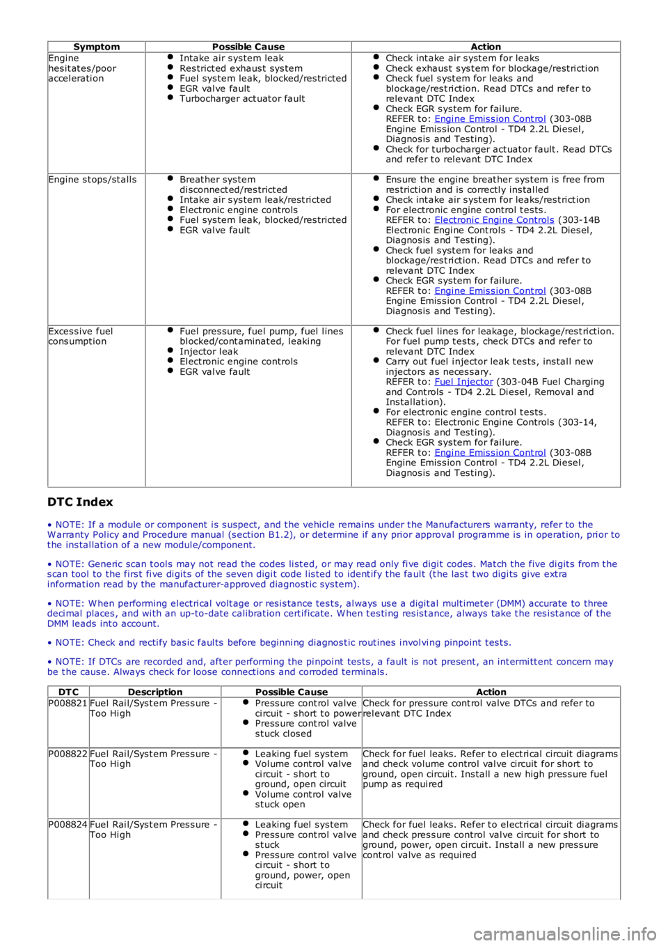
Symptom
Possible Cause Action
Engine
hes it at es /poor
accel erati on Intake air s ys tem leak Res trict ed exhaus t sys tem
Fuel sys tem leak, blocked/res tricted
EGR val ve fault
Turbocharger act uat or fault Check int ake air s yst em for leaks
Check exhaus t s ys t em for blockage/rest ri cti on
Check fuel s yst em for leaks and
bl ockage/res t ri ct ion. Read DTCs and refer to
relevant DTC Index Check EGR s ys tem for fai lure.
REFER t o: Engi ne Emis s ion Cont rol (303-08B
Engine Emis s ion Control - TD4 2.2L Di esel ,
Diagnos is and Tes t ing). Check for t urbocharger act uat or fault . Read DTCs
and refer t o rel evant DTC Index Engine s t ops /st all s
Breat her sys tem
di sconnect ed/res trict ed Intake air s ys tem leak/rest ri cted
El ect ronic engine controls
Fuel sys tem leak, blocked/res tricted
EGR val ve fault Ens ure the engine breat her sys t em i s free from
res tricti on and is correctl y ins tal led Check int ake air s yst em for leaks/res t ri ct ion
For electronic engine control t es ts .
REFER t o: Electroni c Engi ne Control s (303-14B
El ect ronic Engi ne Cont rol s - TD4 2.2L Dies el ,
Diagnos is and Tes t ing). Check fuel s yst em for leaks and
bl ockage/res t ri ct ion. Read DTCs and refer to
relevant DTC Index Check EGR s ys tem for fai lure.
REFER t o: Engi ne Emis s ion Cont rol (303-08B
Engine Emis s ion Control - TD4 2.2L Di esel ,
Diagnos is and Tes t ing). Exces s ive fuel
cons umpt ion Fuel pres sure, fuel pump, fuel l ines
bl ocked/cont aminat ed, l eaki ng Injector l eak
El ect ronic engine controls
EGR val ve fault Check fuel l ines for l eakage, bl ockage/res t ri ct ion.
For fuel pump t es ts , check DTCs and refer to
relevant DTC Index Carry out fuel i njector leak t es ts , ins tal l new
injectors as neces s ary.
REFER t o: Fuel Injector (303-04B Fuel Charging
and Cont rols - TD4 2.2L Di esel , Removal and
Ins tal lati on). For electronic engine control t es ts .
REFER t o: Electroni c Engi ne Control s (303-14,
Diagnos is and Tes t ing). Check EGR s ys tem for fai lure.
REFER t o: Engi ne Emis s ion Cont rol (303-08B
Engine Emis s ion Control - TD4 2.2L Di esel ,
Diagnos is and Tes t ing). DTC Index
• NOTE: If a module or component i s s uspect, and t he vehi cl e remains under t he Manuf acturers warranty, refer to the
W arranty Pol icy and Procedure manual (s ecti on B1.2), or det ermi ne if any pri or appro val programme i s in operat ion, pri or to
t he ins tal lati on of a new modul e/component.
• NOTE: Generic scan t ool s may not read the codes li st ed, or may read only fi ve digi t codes . Mat ch the five di git s from t he
s can tool to the firs t fi ve di git s of the seven digi t code l is ted to ident ify t he fa ul t (t he las t t wo digi ts gi ve ext ra
informat ion read by the manufact urer-approved diagnost ic s ys tem).
• NOTE: W hen performing el ect ri cal volt age or resi s tance tes t s, al ways us e a digit al mult imet er (DMM) accurate to three
deci mal places , and wi th an up-to-date cali brat ion cert ificate. W hen t es ti ng res is t a nce, always take t he res i st ance of t he
DMM leads int o account.
• NOTE: Check and recti fy bas ic faul ts before beginni ng diagnos t ic rout ines i nvol vi n g pinpoint t es t s.
• NOTE: If DTCs are recorded and, aft er performi ng the pi npoi nt tes ts , a fault is no t present , an int ermi tt ent concern may
be t he caus e. Always check for loose connect ions and corroded terminals .
DT C Description Possible Cause Action
P008821 Fuel Rai l/Sys t em Pres s ure -
Too Hi gh Press ure cont rol valve
ci rcuit - s hort t o power Press ure cont rol valve
s t uck cl os ed Check for pres sure cont rol valve DTCs and refer to
rel evant DTC Index
P008822 Fuel Rai l/Sys t em Pres s ure -
Too Hi gh Leaking fuel s ys tem Vol ume cont rol valve
ci rcuit - s hort t o
ground, open circuit Vol ume cont rol valve
s t uck open Check for fuel leaks. Refer t o el ect ri cal circuit di agrams
and check volume control val ve ci rcuit for short to
ground, open circui t. Ins tall a new high pres s ure fuel
pump as requi red
P008824 Fuel Rai l/Sys t em Pres s ure -
Too Hi gh Leaking fuel s ys tem Press ure cont rol valve
s t uck Press ure cont rol valve
ci rcuit - s hort t o
ground, power, open
ci rcuit Check for fuel leaks. Refer t o el ect ri cal circuit di agrams
and check pres s ure control val ve ci rcuit for short to
ground, power, open circui t. Ins tall a new pres s ure
cont rol valve as requi red
Page 1593 of 3229
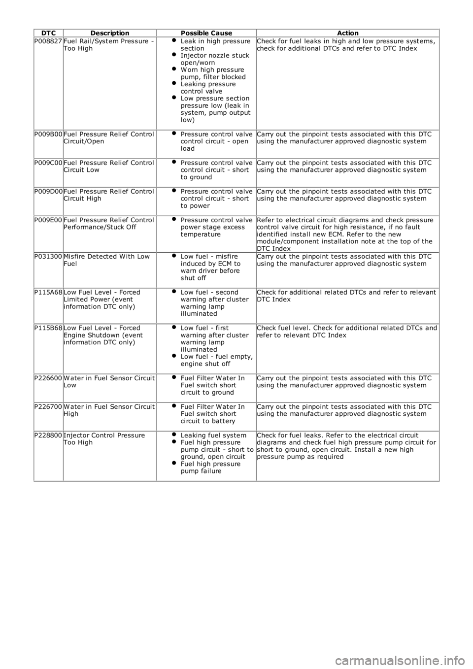
DT C
Description Possible Cause Action
P008827 Fuel Rai l/Sys t em Pres s ure -
Too Hi gh Leak i n high pres s ure
s ecti on Injector nozzl e s t uck
open/worn W orn hi gh pres s ure
pump, fil ter blocked Leaking pres s ure
control val ve Low pres sure s ect ion
press ure low (l eak in
s ys tem, pump out put
l ow) Check for fuel leaks in hi gh and low pres sure s yst ems ,
check for addit ional DTCs and refer t o DTC Index
P009B00 Fuel Pres sure Reli ef Cont rol
Ci rcuit /Open Press ure cont rol valve
control ci rcuit - open
l oad Carry out the pi npoint t es ts as s oci at ed wi th this DTC
usi ng t he manufact urer approved diagnost ic s ys tem
P009C00 Fuel Pres sure Reli ef Cont rol
Ci rcuit Low Press ure cont rol valve
control ci rcuit - s hort
t o ground Carry out the pi npoint t es ts as s oci at ed wi th this DTC
usi ng t he manufact urer approved diagnost ic s ys tem
P009D00 Fuel Pres sure Reli ef Cont rol
Ci rcuit Hi gh Press ure cont rol valve
control ci rcuit - s hort
t o power Carry out the pi npoint t es ts as s oci at ed wi th this DTC
usi ng t he manufact urer approved diagnost ic s ys tem
P009E00 Fuel Pres sure Reli ef Cont rol
Performance/St uck O ff Press ure cont rol valve
power s tage exces s
t emperat ure Refer to electrical ci rcuit diagrams and check pres s ure
cont rol valve circui t for high resi s tance, i f no faul t
identi fi ed ins tal l new ECM. Refer to the new
module/component i nst all at ion not e at t he top of t he
DTC Index
P031300 Mi s fire Det ect ed W i th Low
Fuel Low fuel - mis fire
i nduced by ECM to
warn driver before
s hut off Carry out the pi npoint t es ts as s oci at ed wi th this DTC
usi ng t he manufact urer approved diagnost ic s ys tem
P115A68 Low Fuel Level - Forced
Limit ed Power (event
i nformat ion DTC only) Low fuel - s econd
warning after clus ter
warning l amp
i ll uminated Check for addi ti onal rel ated DTCs and refer t o rel evant
DTC Index
P115B68 Low Fuel Level - Forced
Engine Shutdown (event
i nformat ion DTC only) Low fuel - fi rs t
warning after clus ter
warning l amp
i ll uminated Low fuel - fuel empty,
engine shut off Check fuel l evel . Check for addit ional rel at ed DTCs and
refer t o relevant DTC Index
P226600 W ater in Fuel Sensor Circui t
Low Fuel Filt er W at er In
Fuel s wit ch short
ci rcuit t o ground Carry out the pi npoint t es ts as s oci at ed wi th this DTC
usi ng t he manufact urer approved diagnost ic s ys tem
P226700 W ater in Fuel Sensor Circui t
Hi gh Fuel Filt er W at er In
Fuel s wit ch short
ci rcuit t o batt ery Carry out the pi npoint t es ts as s oci at ed wi th this DTC
usi ng t he manufact urer approved diagnost ic s ys tem
P228800 Injector Control Press ure
Too Hi gh Leaking fuel s ys tem Fuel high pres s ure
pump ci rcuit - s hort t o
ground, open circuit Fuel high pres s ure
pump fail ure Check for fuel leaks. Refer t o t he electrical ci rcuit
diagrams and check fuel high pres s ure pump circuit for
s hort to ground, open circui t. Inst all a new high
pres sure pump as requi red
Page 1601 of 3229
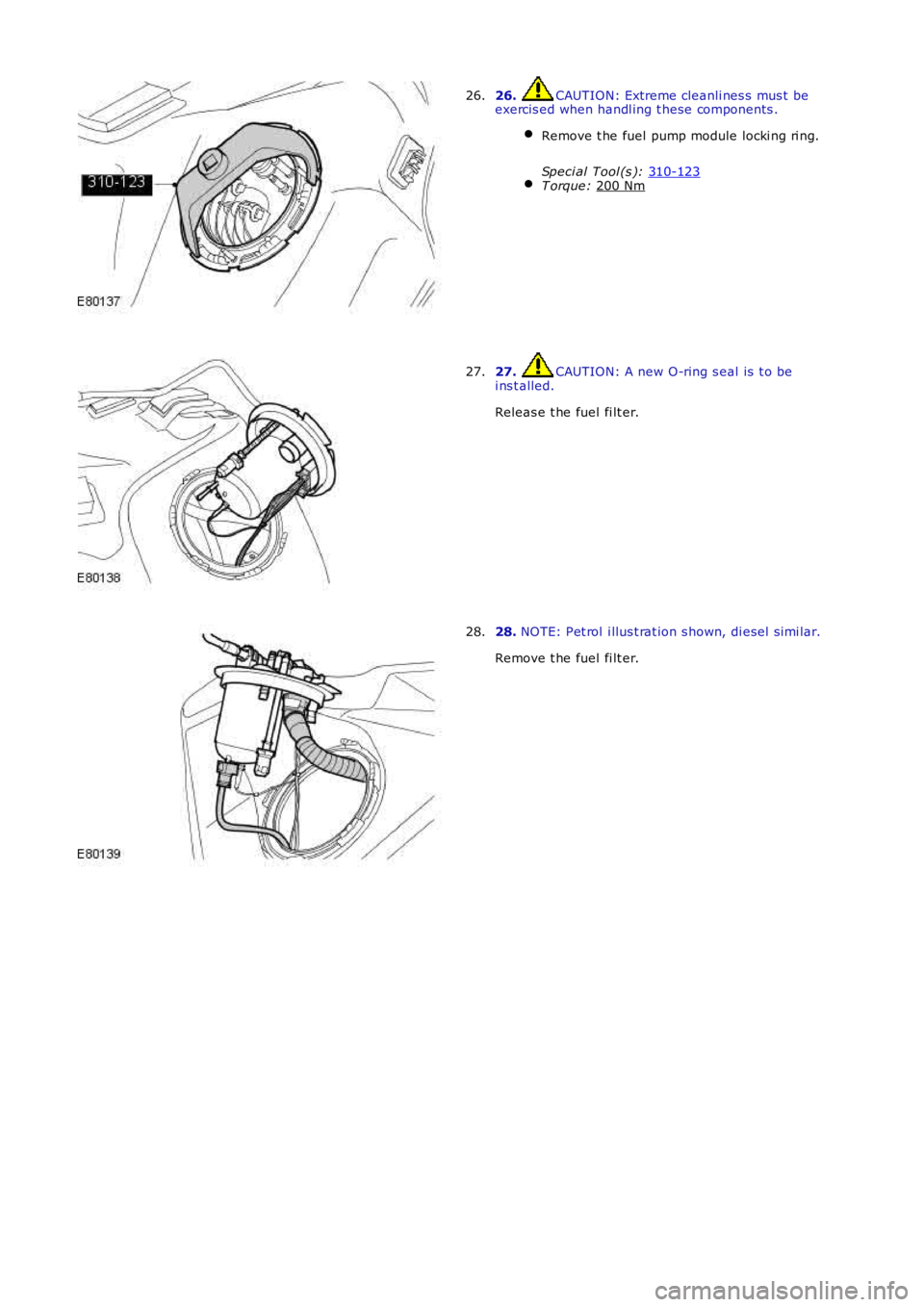
26. CAUTION: Extreme cleanli nes s mus t be
exercis ed when handl ing t hese components .
Remove t he fuel pump module locki ng ri ng.
Speci al Tool (s ): 310-123 T orque:
200 Nm 26.
27. CAUTION: A new O-ring s eal is t o be
i ns t alled.
Releas e t he fuel fi lt er.
27. 28.
NOTE: Pet rol i llus t rat ion s hown, di esel s imi lar.
Remove t he fuel fi lt er.
28.