2006 LAND ROVER FRELANDER 2 fuel pump
[x] Cancel search: fuel pumpPage 1760 of 3229
Publi s hed: 11-May-2011
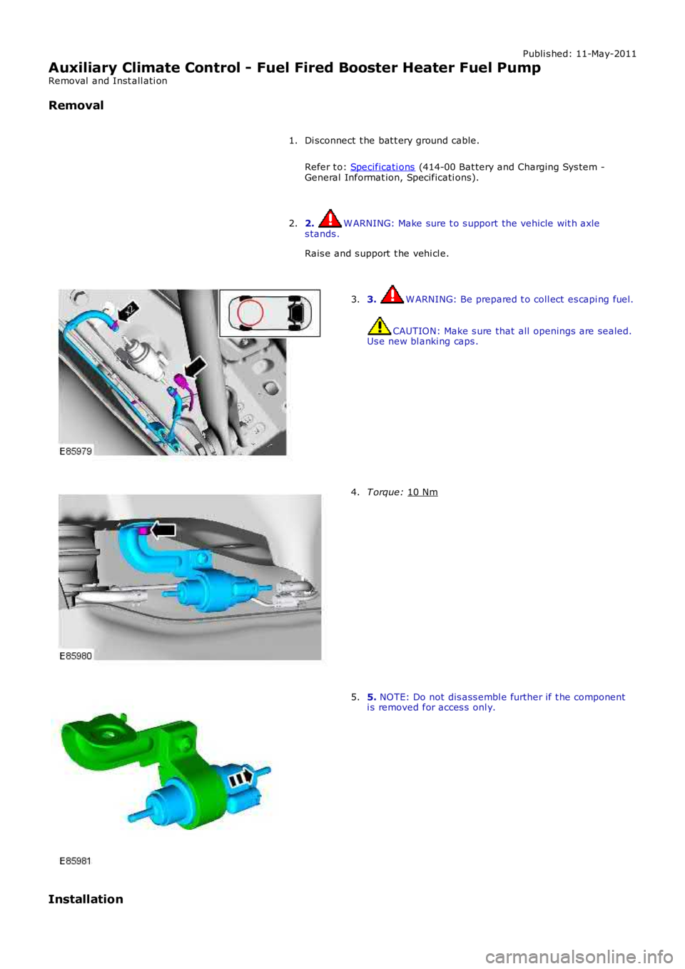
Auxiliary Climate Control - Fuel Fired Booster Heater Fuel Pump
Removal and Inst all ati on
Removal
Di sconnect t he bat t ery ground cable.
Refer t o: Specificati ons (414-00 Bat tery and Charging Sys tem -
General Informat ion, Specificati ons).
1.
2. W ARNING: Make sure t o s upport the vehicle wit h axle
s tands .
Rais e and s upport t he vehi cl e.
2. 3. W ARNING: Be prepared t o coll ect es capi ng fuel.
CAUTION: Make s ure that all openings are sealed.
Us e new bl anki ng caps .
3. T orque:
10 Nm 4.
5.
NOTE: Do not dis ass embl e further if t he component
i s removed for acces s onl y.
5.
Installation
Page 1761 of 3229
Publi s hed: 11-May-2011
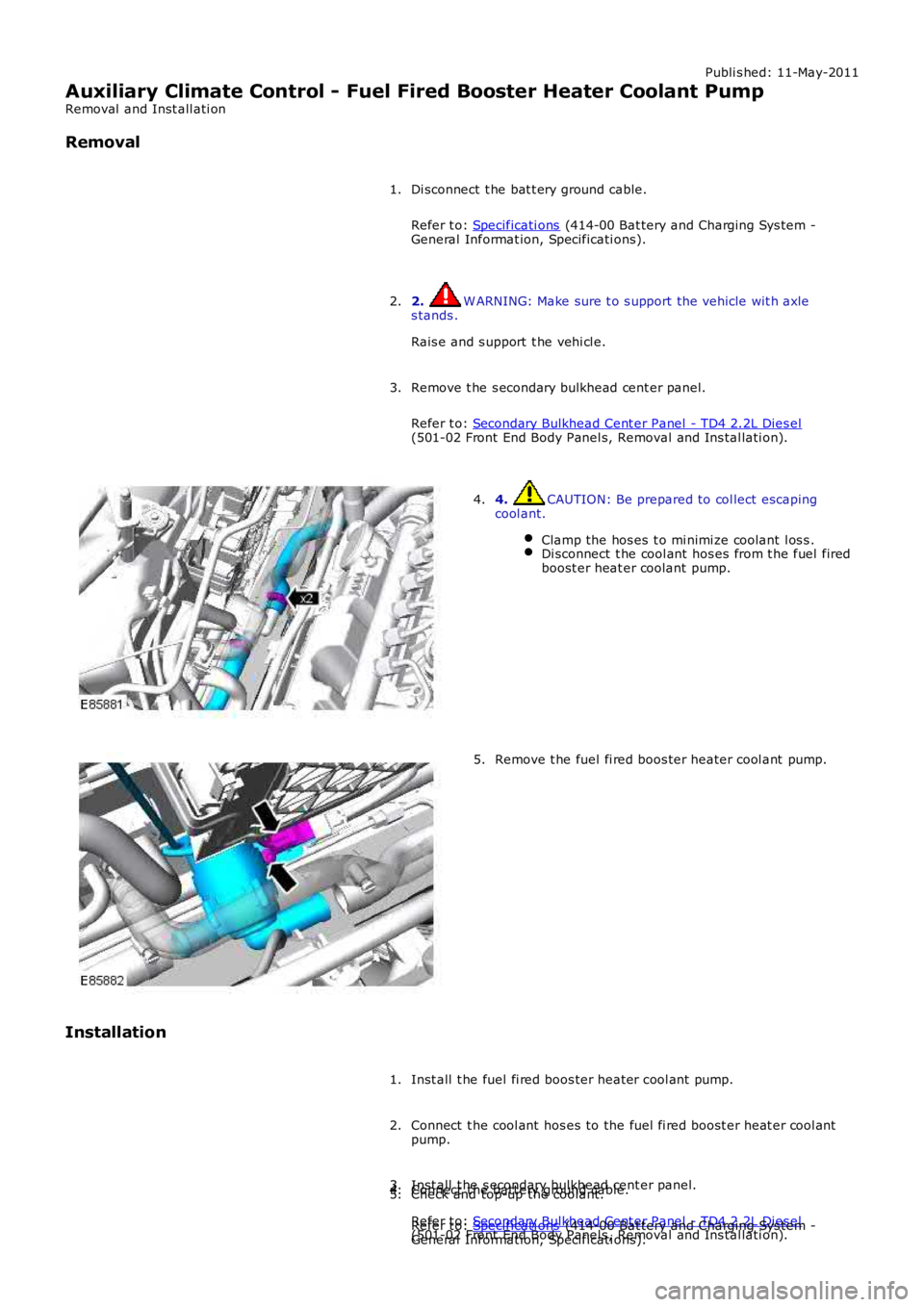
Auxiliary Climate Control - Fuel Fired Booster Heater Coolant Pump
Removal and Inst all ati on
Removal
Di sconnect t he bat t ery ground cable.
Refer t o: Specificati ons (414-00 Bat tery and Charging Sys tem -General Informat ion, Specificati ons).
1.
2. W ARNING: Make sure t o s upport the vehicle wit h axles tands .
Rais e and s upport t he vehi cl e.
2.
Remove t he s econdary bulkhead cent er panel.
Refer t o: Secondary Bulkhead Cent er Panel - TD4 2.2L Dies el(501-02 Front End Body Panel s, Removal and Ins tal lati on).
3.
4. CAUTION: Be prepared to col lect escapingcool ant.
Clamp the hos es t o mi nimi ze coolant l os s .Di sconnect t he cool ant hos es from t he fuel firedboost er heat er coolant pump.
4.
Remove t he fuel fi red boos ter heater cool ant pump.5.
Installation
Inst all t he fuel fi red boos ter heater cool ant pump.1.
Connect t he cool ant hos es to the fuel fi red boost er heat er cool antpump.2.
Inst all t he s econdary bulkhead cent er panel.
Refer t o: Secondary Bulkhead Cent er Panel - TD4 2.2L Dies el(501-02 Front End Body Panel s, Removal and Ins tal lati on).
3.Connect t he batt ery ground cable.
Refer t o: Specificati ons (414-00 Bat tery and Charging Sys tem -General Informat ion, Specificati ons).
4.Check and top-up the coolant.5.
Page 1791 of 3229
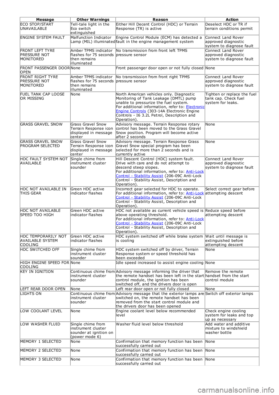
MessageO ther WarningsReasonAction
ECO STOP/STARTUNAVAILABLETel l-tal e li ght in t heEco swi tchext inguis hed
Eit her Hi ll Decent Control (HDC) or TerrainRespons e (TR) i s act iveDes elect HDC or TR i fterrain condit ions permi t
ENGINE SY STEM FAULTMalfunct ion Indi cat orLamp (MIL) il lumi nat edEngi ne Cont rol Module (ECM) has detected afault i n t he engi ne management s ys temConnect Land Roverapproved di agnos ti csys tem t o diagnos e faultFRONT LEFT TY REPRESSURE NOTMONITORED
Amber TPMS indicatorfl ashes for 75 secondsthen remainsil lumi nat ed
No t rans mis s ion from front left TPMSpres sure s ensorConnect Land Roverapproved di agnos ti csys tem t o diagnos e fault
FRONT PASSENGER DOOROPENNoneFront pas s enger door open or not fully cl osedNone
FRONT RIGHT TY REPRESSURE NOTMONITORED
Amber TPMS indicatorfl ashes for 75 secondsthen remainsil lumi nat ed
No t rans mis s ion from front ri ght TPMSpres sure s ensorConnect Land Roverapproved di agnos ti csys tem t o diagnos e fault
FUEL TANK CAP LOOSEOR MISSINGNoneNort h American vehi cl es onl y. Diagnos t icMonit oring of Tank Leakage (DMTL) pumpunabl e to pres surize t he fuel s yst em.For addit ional informati on, refer t o: Elect roni cEngi ne Cont rol s (303-14A Electroni c Engi neCont rol s - I6 3.2L Pet rol, Des cri pt ion andOperati on).
Ti ght en or repl ace t he fueltank cap. Check fuelsys tem for l eaks .
GRASS GRAVEL SNOWGras s Gravel SnowTerrai n Res pons e i condis played in mess agecent er
Advi sory mes s age. Terrain Res pons e rotarycont rol has been moved to the Grass GravelSnow posi ti on. Program will become acti veaft er 2 s econds
None
GRASS GRAVEL SNOWPROGRAM SELECTEDGras s Gravel SnowTerrai n Res pons e i condis played in mess agecent er
Advi sory mes s age. Terrain Res pons e Gras sGravel Snow special program has beens el ect ed for more t han 2 s econds and i scurrent ly acti ve
None
HDC FAULT SY STEM NOTAVAILABLESingle chime fromins trument cl ust ers ounder
Hil l Des cent Cont rol (HDC) sys tem faul t.Dri ve wit h care and do not at tempt t odes cend s teep s lopes .For addit ional informati on, refer t o: Ant i-LockCont rol - St abi li ty As s is t (206-09C Anti -LockCont rol - St abi li ty As s is t , Des cri pti on andOperati on).
Connect Land Roverapproved di agnos ti csys tem t o diagnos e fault
HDC NOT AVAILABLE INTHIS GEARGreen HDC act iveindicator flas hesIncorrect gear s el ect ed for HDC to operate.For addit ional informati on, refer t o: Ant i-LockCont rol - St abi li ty As s is t (206-09C Anti -LockCont rol - St abi li ty As s is t , Des cri pti on andOperati on).
Sel ect correct gear beforeat t empt ing des cent
HDC NOT AVAILABLESPEED TOO HIGHGreen HDC act iveindicator flas hesHDC not avai lable as current vehi cl e s peed isabove operat ing t hres hold.For addit ional informati on, refer t o: Ant i-LockCont rol - St abi li ty As s is t (206-09C Anti -LockCont rol - St abi li ty As s is t , Des cri pti on andOperati on).
Reduce s peed beforeat t empt ing des cent
HDC TEMPORARILY NOTAVAILABLE SY STEMCOOLING
Green HDC act iveindicator flas hesHDC s yst em swi tched off whi le brake s ys t emis cooli ngW ait unt il mes sage i sext inguis hed beforeat t empt ing des cent
HDC SW ITCHED O FFSingle chime fromins trument cl ust ers ounder
HDC s yst em swi tched off by driver, TerrainRespons e s ys t em or s peed thres hold hasbeen exceeded
None
HIGH ENGINE SPEED FORCOOLINGNoneIdl e s peed increased to as s is t engine cool ingNone
KEY IN IGNITIONCont inuous chi me fromins trument cl ust ers ounder
Advi sory mes s age informing the driver thatthe remot e hands et has been left i n t he s tartcont rol module, t he ignit ion has beens wit ched off, and t he dri vers door i s open
Remove t he remotehands et from t he s tartcontrol modul e
LEFT REAR DOOR O PENNoneLeft rear door open or not ful ly cl os edNone
LIGHTS ONCont inuous chi me fromins trument cl ust ers ounder
Advi sory mes s age that t he ext eri or l amps ares wit ched on, t he remot e hands et has beenremoved from the s t art control modul e andthe drivers door has been opened
Swi tch off ext eri or lamps
LOW COOLANT LEVELNoneEngi ne cool ant l evel below recommendedlevelCheck engine cool ingsys tem for l eaks and t opup as neces sary
LOW W ASHER FLUIDSingle chime fromins trument cl ust ers ounder at ignit ion on(power mode 6)
W as her flui d level bel ow t hres hol dAdd water and addi ti vemixt ure t o wi nds hiel dwas her bott le
MEMORY 1 SELECTEDNoneConfirmati on t hat memory funct ion has beens uccess ful ly carried outNone
MEMORY 2 SELECTEDNoneConfirmati on t hat memory funct ion has beens uccess ful ly carried outNone
MEMORY 3 SELECTEDNoneConfirmati on t hat memory funct ion has beens uccess ful ly carried outNone
Page 1833 of 3229
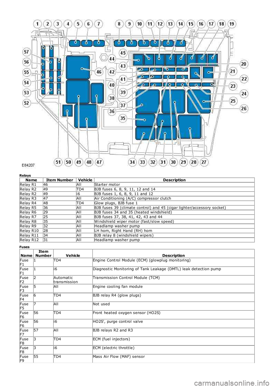
Relays
NameItem NumberVehicleDescriptionRelay R146Al lStarter mot or
Relay R249TD4BJB fus es 6, 8, 9, 11, 12 and 14
Relay R249i 6BJB fus es 1, 6, 8, 9, 11 and 12Relay R347Al lAir Condit ioning (A/C) compres s or cl utch
Relay R448TD4Glow plugs , BJB fus e 1
Relay R536Al lBJB fus es 39 (climat e control) and 45 (cigar light er/access ory socket)Relay R629Al lBJB fus es 34 and 35 (heated wi nds hiel d)
Relay R725Al lBJB fus es 37, 38, 41, 42, 43 and 44
Relay R835Al lW i ndshi el d wi per mot or (fast /sl ow s peed)Relay R932Al lHeadlamp was her pump
Relay R1028Al lLH horn, Ri ght Hand (RH) horn
Relay R1134Al lBJB rel ay 8 (winds hi eld wipers )Relay R1231Al lHeadlamp was her pump
Fuses
NameItemNumberVehicleDescription
FuseF11TD4Engine Cont rol Module (ECM) (gl owpl ug monit ori ng)
FuseF11i 6Diagnos t ic Monit ori ng of Tank Leakage (DMTL) leak det ect ion pump
FuseF22Automat ict rans mis s ionTransmis si on Control Module (TCM)
FuseF35AllEngine cooli ng fan modul e
FuseF46TD4BJB relay R4 (glow plugs)
FuseF57AllNot us ed
FuseF656TD4Front heat ed oxygen s ensor (HO2S)
FuseF656i 6HO2S', purge cont rol valve
FuseF757AllBJB relays R2 and R3
FuseF83TD4ECM (fuel injectors)
FuseF83i 6ECM (el ect ri c thrott le)
FuseF955TD4Mas s Ai r Flow (MAF) s ens or
Page 1834 of 3229
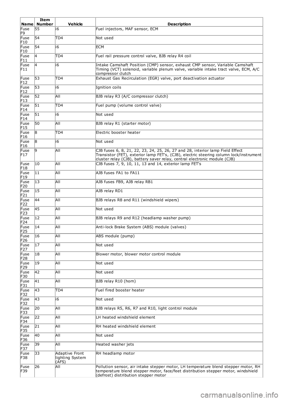
NameItemNumberVehicleDescription
FuseF955i 6Fuel inject ors , MAF s ens or, ECM
FuseF1054TD4Not us ed
FuseF1054i 6ECM
FuseF114TD4Fuel rai l press ure cont rol valve, BJB relay R4 coi l
FuseF114i 6Int ake Cams haft Pos it ion (CMP) s ens or, exhaust CMP sens or, Vari able Cams haftTi ming (VCT) s olenoi d, variable pl enum valve, variable intake t ract valve, ECM, A/Ccompres s or cl utch
FuseF1253TD4Exhaust Gas Recircul ati on (EGR) valve, port deact ivati on act uator
FuseF1253i 6Ignit ion coil s
FuseF1352AllBJB relay R3 (A/C compres sor clut ch)
FuseF1451TD4Fuel pump (vol ume cont rol valve)
FuseF1451i 6Not us ed
FuseF1550AllBJB relay R1 (s tarter mot or)
FuseF168TD4El ect ri c boos t er heat er
FuseF168i 6Not us ed
FuseF179AllCJB fus es 6, 8, 21, 22, 23, 24, 25, 26, 27 and 28, i nt eri or lamp Fi el d EffectTransi st or (FET), ext erior l amp FET's , (CJB), electric st eering col umn lock/i ns t rumentcl us t er relay (CJB), batt ery s aver relay, cent ral electronic module (CJB)
FuseF1810AllCJB fus es 7, 9, 10, 11, 13 and 14, ext erior l amp FET's
FuseF1911AllAJB fus es FA1 to FA11
FuseF2013AllAJB fus es FB9, AJB rel ay RB1
FuseF2115AllAJB relay RD1
FuseF2244AllBJB relays R8 and R11 (winds hield wipers )
FuseF2345AllNot us ed
FuseF2412AllBJB relays R9 and R12 (headl amp was her pump)
FuseF2514AllAnt i-lock Brake Sys tem (ABS) module (valves )
FuseF2616AllABS modul e (pump)
FuseF2717AllNot us ed
FuseF2818AllBl ower motor, bl ower motor cont rol module
FuseF2919AllNot us ed
FuseF3042AllNot us ed
FuseF3141AllBJB relay R10 (horn)
FuseF3243TD4Fuel fi red boos ter heater
FuseF3243i 6Not us ed
FuseF3320AllBJB relays R5, R6, R7 and R10, l ight cont rol module
FuseF3422AllLH heat ed wi nds hield element
FuseF3521AllRH heat ed wi nds hiel d element
FuseF3640AllNot us ed
FuseF3739AllHeat ed was her jets
FuseF3833Adapti ve Frontl ighti ng Sys t em(AFS)
RH headl amp mot or
FuseF3926AllPol luti on s ens or, ai r int ake st epper mot or, LH t emperat ure bl end st epper mot or, RHtemperat ure bl end st epper mot or, face/feet dis t ri but ion s t epper mot or, wi nds hield(defrost ) dis t ri but ion s t epper mot or
Page 1836 of 3229
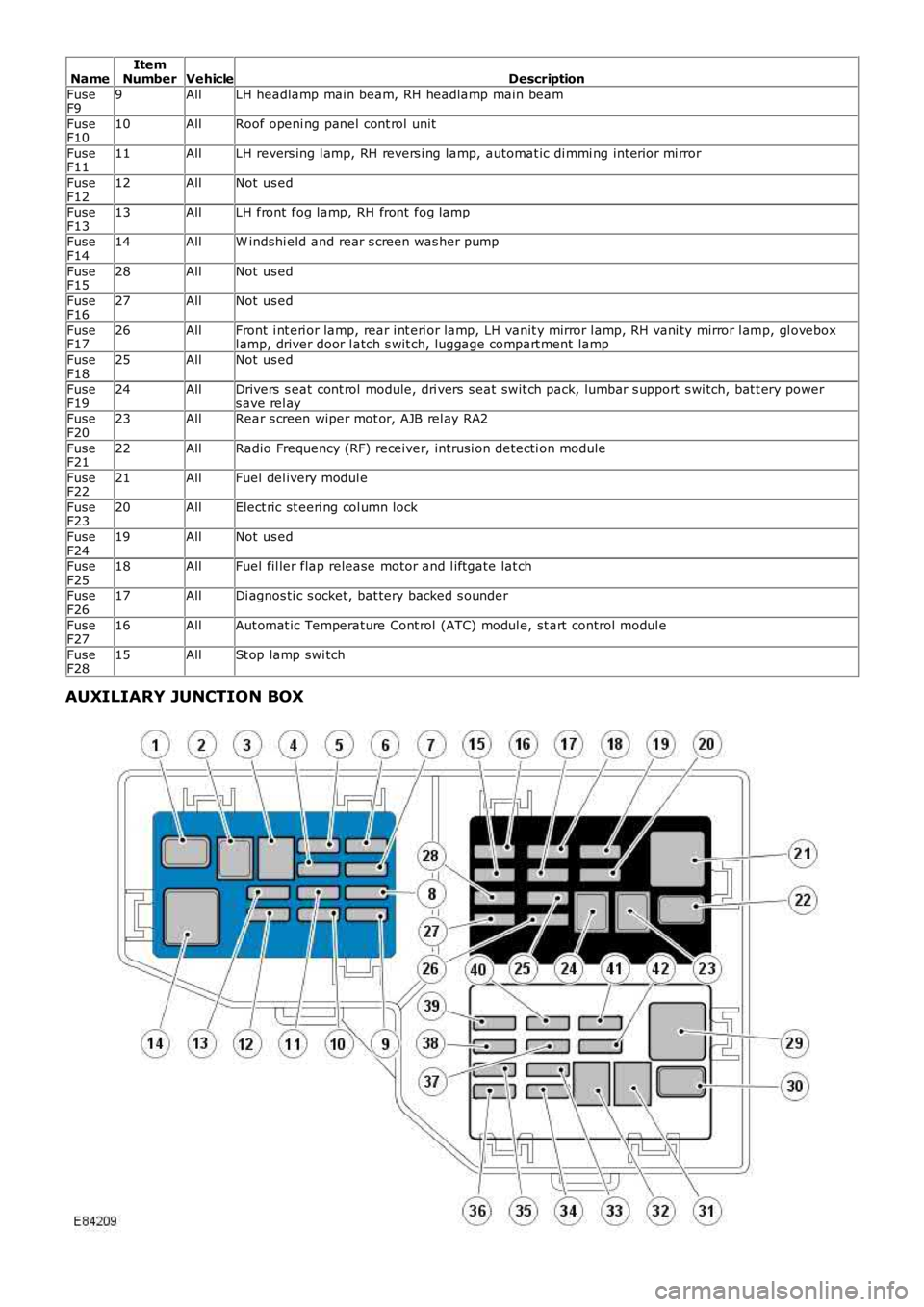
NameItemNumberVehicleDescription
FuseF99AllLH headlamp main beam, RH headlamp main beam
FuseF1010AllRoof openi ng panel cont rol unit
FuseF1111AllLH revers ing l amp, RH revers i ng lamp, automat ic di mmi ng int erior mi rror
FuseF1212AllNot us ed
FuseF1313AllLH front fog lamp, RH front fog lamp
FuseF1414AllW indshi eld and rear s creen was her pump
FuseF1528AllNot us ed
FuseF1627AllNot us ed
FuseF1726AllFront i nt eri or lamp, rear i nt eri or lamp, LH vanit y mirror l amp, RH vani ty mirror l amp, gl oveboxl amp, driver door l atch s wit ch, luggage compart ment lamp
FuseF1825AllNot us ed
FuseF1924AllDrivers s eat cont rol module, dri vers s eat swit ch pack, lumbar s upport s wi tch, bat t ery powers ave rel ayFuseF2023AllRear s creen wiper mot or, AJB rel ay RA2
FuseF2122AllRadio Frequency (RF) receiver, intrusi on detecti on module
FuseF2221AllFuel del ivery modul e
FuseF2320AllElect ric st eeri ng col umn lock
FuseF2419AllNot us ed
FuseF2518AllFuel fil ler flap release motor and l iftgate lat ch
FuseF2617AllDi agnos ti c s ocket, bat tery backed s ounder
FuseF2716AllAut omat ic Temperature Cont rol (ATC) modul e, st art control modul e
FuseF2815AllSt op lamp swi tch
AUXILIARY JUNCTION BOX
Page 1853 of 3229
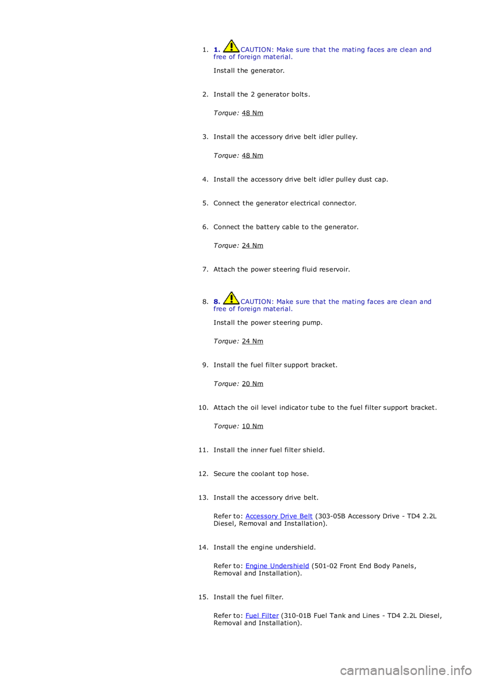
1. CAUTION: Make s ure that the mati ng faces are cl ean and
free of foreign mat eri al.
Inst all t he generat or.
1.
Inst all t he 2 generator bolt s .
T orque: 48 Nm 2.
Inst all t he acces sory dri ve bel t idl er pull ey.
T orque: 48 Nm 3.
Inst all t he acces sory dri ve bel t idl er pull ey dust cap.
4.
Connect t he generator electrical connect or.
5.
Connect t he batt ery cable t o t he generator.
T orque: 24 Nm 6.
At tach t he power s t eering flui d res ervoir.
7.
8. CAUTION: Make s ure that the mati ng faces are cl ean and
free of foreign mat eri al.
Inst all t he power s t eering pump.
T orque: 24 Nm 8.
Inst all t he fuel fi lt er support bracket.
T orque: 20 Nm 9.
At tach t he oil level indicator t ube to the fuel fil ter s upport bracket .
T orque: 10 Nm 10.
Inst all t he inner fuel fi lt er shi el d.
11.
Secure t he cool ant t op hos e.
12.
Inst all t he acces sory dri ve bel t.
Refer t o: Acces sory Dri ve Belt (303-05B Acces sory Drive - TD4 2.2L
Di es el, Removal and Ins tal lat ion).
13.
Inst all t he engi ne undershi eld.
Refer t o: Engi ne Unders hi eld (501-02 Front End Body Panel s ,
Removal and Ins tall ati on).
14.
Inst all t he fuel fi lt er.
Refer t o: Fuel Fil ter (310-01B Fuel Tank and Lines - TD4 2.2L Dies el ,
Removal and Ins tall ati on).
15.
Page 2061 of 3229
opened. The remot e handset i s removed from the st art control modul e by gentl y pushi ng the remote hands et int o t he st artcont rol module and releas ing. The s tart cont rol module mot or wil l then drive t he remot e hands et out from t he s lot as l ongas t he ignit ion i s off.
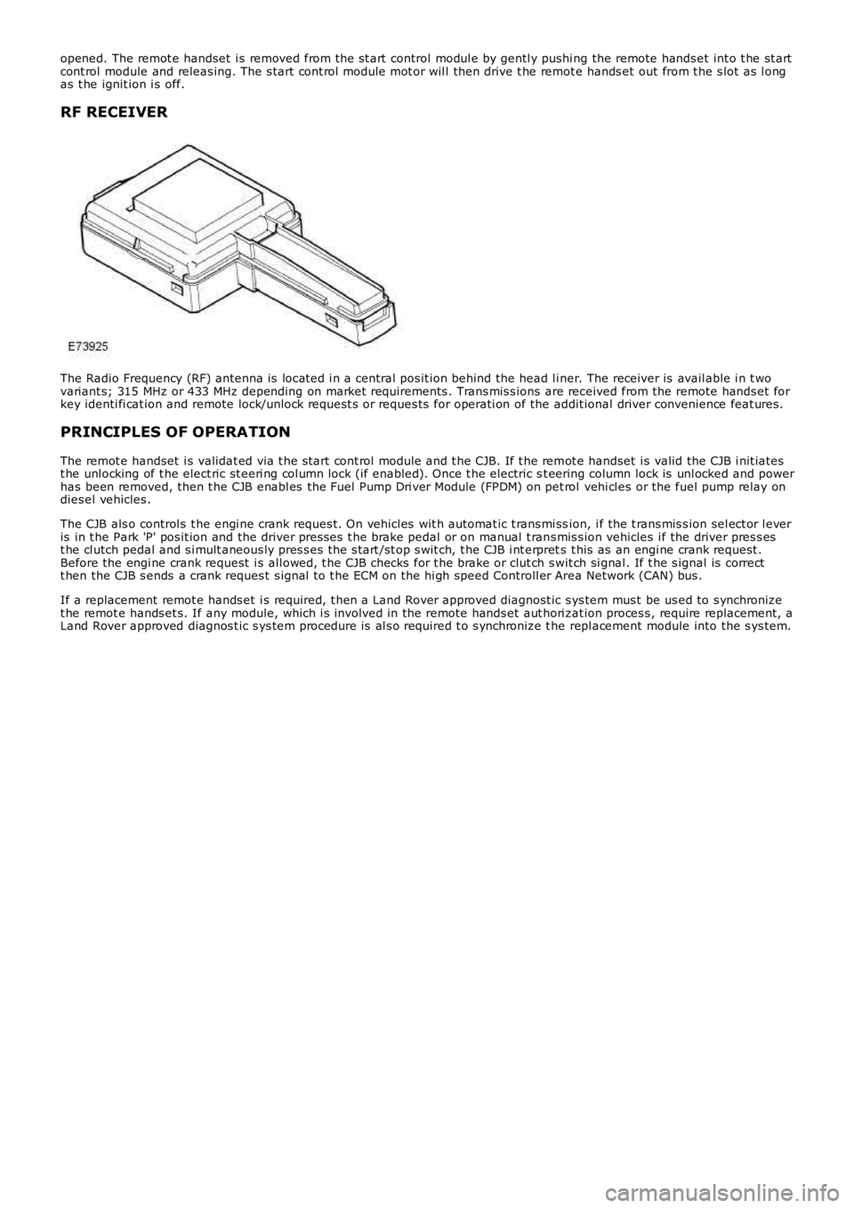
RF RECEIVER
The Radio Frequency (RF) antenna is locat ed i n a central pos it ion behind the head l iner. The receiver is avail able i n t wovariant s; 315 MHz or 433 MHz depending on market requirements . Trans mis s ions are received from the remote hands et forkey identi fi cat ion and remote lock/unlock request s or reques ts for operati on of the addit ional driver convenience feat ures.
PRINCIPLES OF OPERATION
The remot e handset i s validat ed via t he s tart cont rol module and t he CJB. If t he remot e handset i s valid the CJB i nit iatest he unl ocking of t he elect ric st eeri ng col umn lock (if enabled). Once t he electric st eering column lock is unl ocked and powerhas been removed, then t he CJB enabl es the Fuel Pump Dri ver Module (FPDM) on pet rol vehi cl es or the fuel pump relay ondies el vehicles .
The CJB als o control s t he engi ne crank reques t. On vehicl es wit h automat ic t rans mi ssion, i f the t rans mis s ion sel ect or l everis in t he Park 'P' pos it ion and the driver pres ses t he brake pedal or on manual t rans mis s ion vehicles i f the driver pres s est he cl utch pedal and s i mult aneous ly pres s es t he s tart /st op s wit ch, t he CJB i nt erprets t his as an engi ne crank request .Before the engi ne crank request i s all owed, t he CJB checks for t he brake or clut ch swit ch si gnal . If t he s ignal is correctt hen the CJB s ends a crank reques t s ignal t o t he ECM on the hi gh speed Controll er Area Network (CAN) bus .
If a replacement remot e hands et i s required, t hen a Land Rover approved diagnost ic sys tem mus t be us ed to s ynchronizet he remot e hands et s. If any module, which i s involved in the remote hands et aut hori zat ion proces s , require replacement, aLand Rover approved diagnos t ic s ys tem procedure is al s o required t o s ynchronize t he repl acement module into the s ys tem.