2006 LAND ROVER FRELANDER 2 fuel pump
[x] Cancel search: fuel pumpPage 1743 of 3229
FFBH antenna mat chi ng uni t and a remote hands et for operati on of the s ys tem. The FFBH unit remains as previ ous l y fi tt edbut has upgraded s oftware. The Engine Cont rol Modul e (ECM) als o has a s oft ware cal ibrat ion upgrade. The ins trumentclus ter mes s age cent er di spl ays FFBH mes s ages when required.
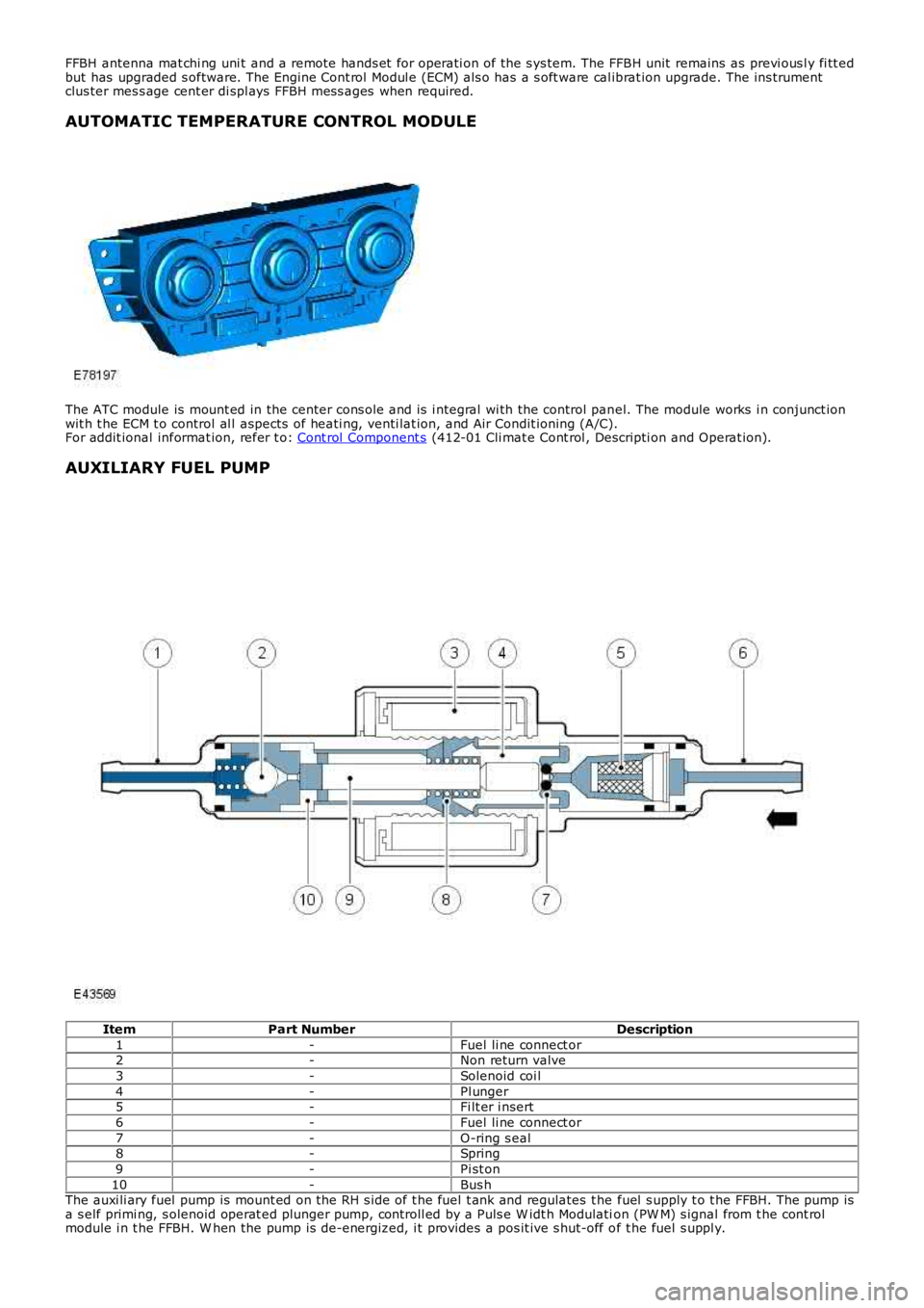
AUTOMATIC TEMPERATURE CONTROL MODULE
The ATC module is mount ed in the center cons ole and is i ntegral wi th the control panel. The module works i n conjunct ionwit h t he ECM t o control al l aspects of heati ng, venti lat ion, and Air Condit ioning (A/C).For addit ional informat ion, refer t o: Cont rol Component s (412-01 Cli mat e Cont rol , Descripti on and Operat ion).
AUXILIARY FUEL PUMP
ItemPart NumberDescription
1-Fuel li ne connect or2-Non return valve
3-Solenoid coi l
4-Pl unger5-Fi lt er i nsert
6-Fuel li ne connect or
7-O-ring s eal8-Spring
9-Pi st on
10-Bus hThe auxi li ary fuel pump is mount ed on the RH s ide of t he fuel t ank and regulates t he fuel s upply t o t he FFBH. The pump isa s elf primi ng, s olenoid operat ed plunger pump, controll ed by a Puls e W idt h Modulation (PW M) s ignal from t he cont rolmodule i n t he FFBH. W hen the pump is de-energized, i t provides a pos it ive s hut-off of t he fuel s uppl y.
Page 1744 of 3229
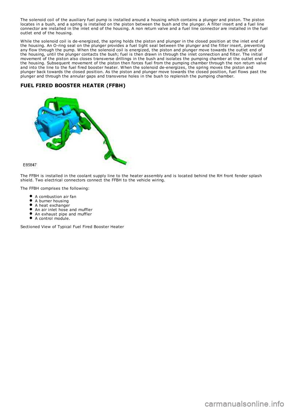
The s olenoi d coil of the auxil iary fuel pump i s ins tal led around a hous ing which cont ains a pl unger and pis t on. The pi st onlocates i n a bus h, and a s pri ng is i nst all ed on t he pis ton bet ween the bus h and t he plunger. A fil ter i nsert and a fuel l ineconnector are ins tal led i n the inlet end of t he hous ing. A non return valve and a fuel line connect or are i nst all ed in the fueloutl et end of t he housi ng.
W hi le t he s olenoid coil i s de-energized, the spring holds t he pis t on and plunger i n t he clos ed pos i ti on at the i nlet end oft he hous ing. An O-ri ng s eal on the pl unger provides a fuel ti ght s eal bet ween t he plunger and t he filt er ins ert , prevent ingany fl ow t hrough t he pump. W hen the sol enoi d coi l is energi zed, t he pis ton and pl unger move t owards t he outl et end oft he hous ing, unti l the pl unger cont act s t he bush; fuel i s t hen drawn i n t hrough the i nlet connecti on and fi lt er. The i ni ti almovement of t he pis t on als o clos es t rans verse dril li ngs in t he bus h and is olat es the pumpi ng chamber at t he out let end oft he hous ing. Subsequent movement of t he pis ton then forces fuel from t he pumping chamber through t he non return val veand int o t he li ne to the fuel fi red boost er heat er. W hen the s olenoid de-energizes , the s pri ng moves the pi s ton andplunger back t owards t he cl osed pos it ion. As t he pis t on and plunger move towards t he clos ed posi ti on, fuel fl ows pas t t heplunger and through t he annul ar gaps and t rans vers e holes i n t he bus h t o replenis h the pumping chamber.
FUEL FIRED BOOSTER HEATER (FFBH)
The FFBH is ins tall ed in the coolant s uppl y li ne to the heat er as s embly and i s located behind the RH front fender s plas hs hield. Two el ect ri cal connectors connect the FFBH t o t he vehi cl e wi ri ng.
The FFBH compris es t he fol lowing:
A combus ti on air fanA burner housi ngA heat exchangerAn air i nlet hose and mufflerAn exhaus t pipe and mufflerA control modul e.
Sect ioned View of Typi cal Fuel Fired Boost er Heater
Page 1745 of 3229
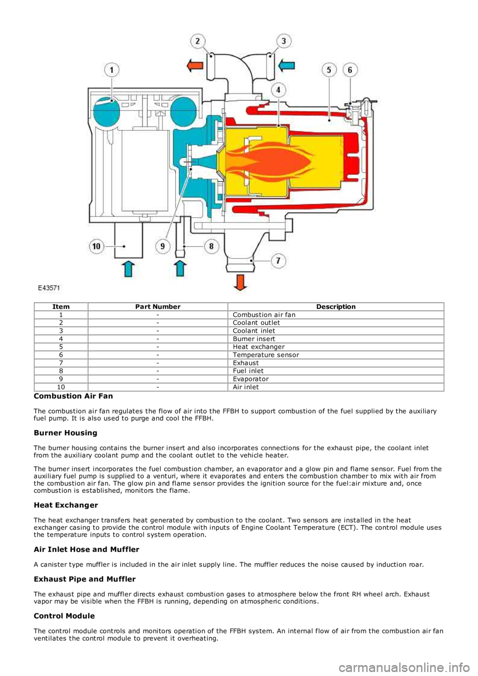
ItemPart NumberDescription
1-Combus t ion ai r fan2-Cool ant out let
3-Cool ant inlet
4-Burner ins ert5-Heat exchanger
6-Temperature s ens or
7-Exhaus t8-Fuel i nl et
9-Evaporat or
10-Air i nl et
Combustion Air Fan
The combus t ion ai r fan regul at es t he fl ow of air i nto t he FFBH t o s upport combus ti on of the fuel suppli ed by t he auxi liaryfuel pump. It i s als o us ed t o purge and cool the FFBH.
Burner Housing
The burner hous ing cont ai ns the burner i nsert and als o i ncorporat es connecti ons for t he exhaus t pipe, the coolant inl etfrom the auxil iary coolant pump and t he cool ant out let t o t he vehi cl e heater.
The burner ins ert i ncorporat es t he fuel combus t ion chamber, an evaporator and a gl ow pin and fl ame s ens or. Fuel from t heauxi li ary fuel pump is s uppl ied t o a vent uri, where it evaporat es and ent ers t he combust ion chamber to mix wit h air fromt he combus ti on air fan. The gl ow pin and fl ame s ens or provides t he igni ti on source for t he fuel:air mi xture and, oncecombus t ion i s es tabli shed, monit ors t he flame.
Heat Exchang er
The heat exchanger t ransfers heat generated by combus ti on t o the coolant . Two s ens ors are i nst all ed in t he heatexchanger cas ing t o provide the control modul e wi th i nput s of Engine Coolant Temperature (ECT). The cont rol module us est he temperat ure inputs t o control s ys tem operati on.
Air Inlet Hose and Muffler
A canis ter t ype muffler i s included in the ai r inlet s upply l ine. The muffler reduces the noi se caus ed by inducti on roar.
Exhaust Pipe and Muffler
The exhaus t pipe and muffl er di rects exhaus t combus ti on gases t o at mos phere below t he front RH wheel arch. Exhaus tvapor may be vi s ible when the FFBH i s running, dependi ng on atmos pheri c condit ions .
Control Module
The cont rol module cont rols and moni tors operati on of the FFBH sys tem. An int ernal flow of ai r from t he combust ion ai r fanvent il ates t he cont rol module to prevent i t overheat ing.
Page 1746 of 3229
The cont rol module is powered by a permanent feed from the Bat t ery Junct ion Box (BJB), and communi cat es wi th t he ATCmodule over the medium speed Controller Area Network (CAN) bus .
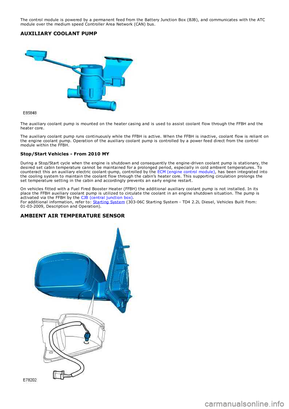
AUXILIARY COOLANT PUMP
The auxi li ary coolant pump is mount ed on t he heater cas i ng and is us ed t o as si s t coolant flow through t he FFBH and t heheat er core.
The auxi li ary coolant pump runs conti nuous ly whi le the FFBH i s act ive. W hen t he FFBH is inact ive, cool ant flow is reli ant ont he engi ne cool ant pump. Operat ion of t he auxi li ary cool ant pump is controll ed by a power feed di rect from t he cont rolmodule wit hi n t he FFBH.
Stop/Start Vehicles - From 2010 MY
Duri ng a St op/Start cycle when the engine i s s hutdown and consequent ly the engine-driven coolant pump is st ati onary, thedesi red s et cabi n t emperature cannot be mai ntai ned for a prol onged period, especially in col d ambient t emperatures . Tocount eract this an auxi li ary electric coolant -pump, cont rol led by t he ECM (engi ne cont rol module), has been i ntegrat ed int ot he cooli ng s yst em t o mai ntai n the coolant flow t hrough t he cabi n’s heater core. This s upporti ng circulat ion prolongs thes et temperat ure set ti ng in the cabin and accordingly prevent s an earl y engi ne res t art .
On vehicles fit ted wit h a Fuel Fi red Boos ter Heat er (FFBH) t he addit ional auxil iary cool ant pump is not ins t al led. In it splace t he FFBH auxi liary cool ant pump is ut il ized t o circulat e t he cool ant i n an engine s hutdown s i tuati on. The pump isact ivat ed via t he FFBH by t he CJB (central junct ion box).For addit ional informat ion, refer t o: Starti ng Sys t em (303-06C Starti ng Syst em - TD4 2.2L Di es el, Vehicles Bui lt From:01-03-2009, Descripti on and Operat ion).
AMBIENT AIR TEMPERATURE SENSOR
Page 1750 of 3229
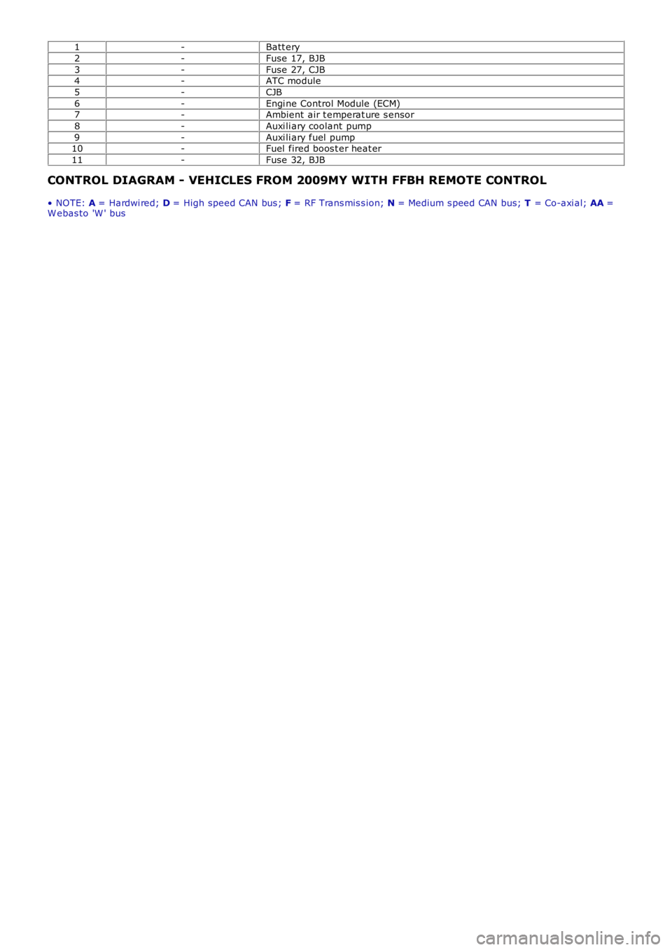
1-Batt ery
2-Fuse 17, BJB
3-Fuse 27, CJB4-ATC module
5-CJB
6-Engi ne Control Module (ECM)7-Ambient air t emperat ure s ensor
8-Auxi li ary coolant pump
9-Auxi li ary fuel pump10-Fuel fired boos t er heat er
11-Fuse 32, BJB
CONTROL DIAGRAM - VEHICLES FROM 2009MY WITH FFBH REMOTE CONTROL
• NOTE: A = Hardwi red; D = High speed CAN bus ; F = RF Trans mis s ion; N = Medium s peed CAN bus; T = Co-axi al; AA =W ebas to 'W ' bus
Page 1751 of 3229
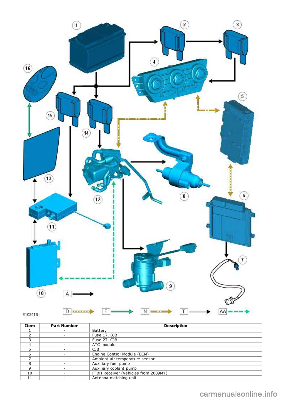
ItemPart NumberDescription
1-Bat tery2-Fus e 17, BJB
3-Fus e 27, CJB
4-ATC modul e5-CJB
6-Engine Cont rol Modul e (ECM)
7-Ambi ent ai r temperat ure sens or8-Auxil iary fuel pump
9-Auxil iary coolant pump
10-FFBH Receiver (Vehicles from 2009MY )11-Ant enna matching unit
Page 1752 of 3229
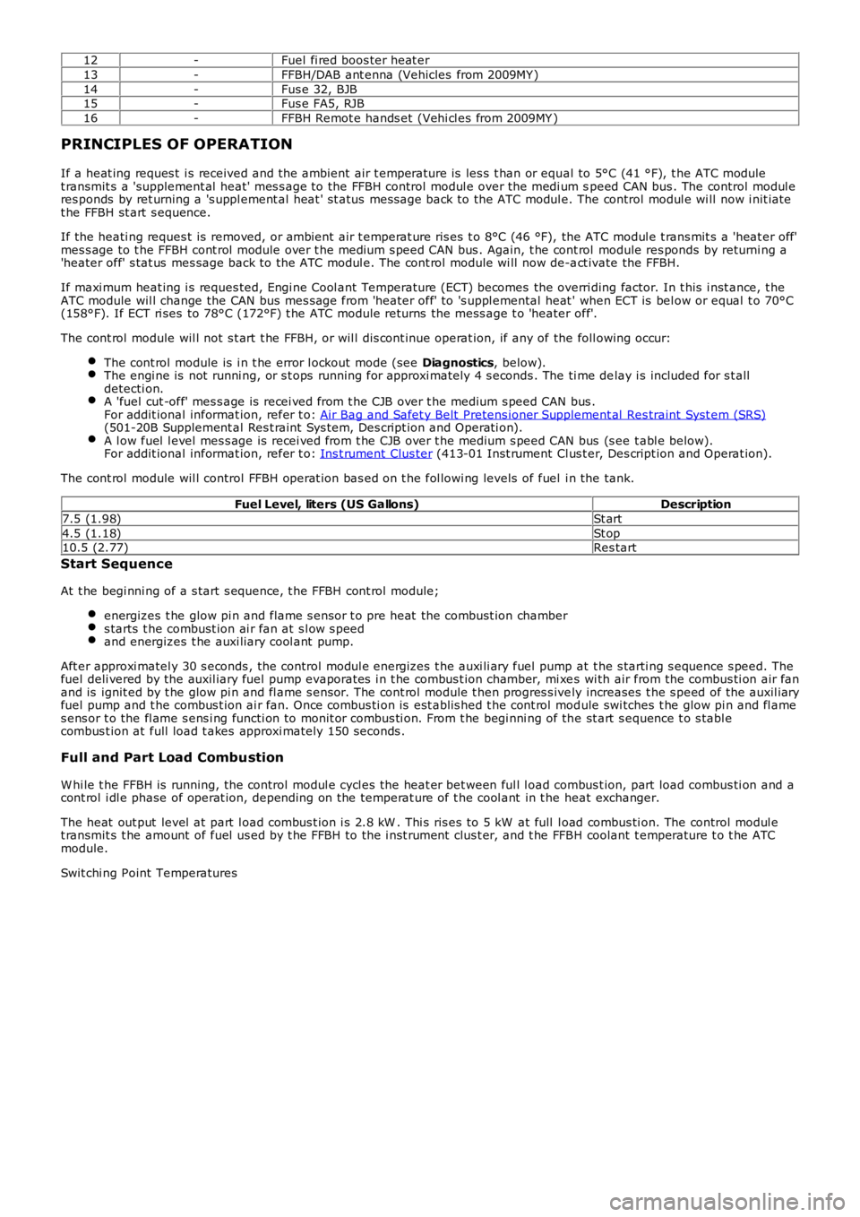
12-Fuel fi red boos ter heat er
13-FFBH/DAB ant enna (Vehicles from 2009MY )
14-Fus e 32, BJB15-Fus e FA5, RJB
16-FFBH Remot e hands et (Vehi cl es from 2009MY )
PRINCIPLES OF OPERATION
If a heat ing reques t i s received and t he ambient air t emperature is les s t han or equal to 5°C (41 °F), t he ATC modulet ransmit s a 'supplement al heat' mes s age to the FFBH control modul e over the medi um speed CAN bus . The control modul eres ponds by ret urning a 's uppl ement al heat ' st atus mess age back to the ATC modul e. The control modul e wi ll now i nit iatet he FFBH st art s equence.
If the heati ng reques t is removed, or ambient air t emperat ure ris es t o 8°C (46 °F), the ATC modul e t rans mit s a 'heat er off'mes s age to t he FFBH cont rol module over t he medium s peed CAN bus . Again, t he cont rol module res ponds by returni ng a'heater off' s tat us mes sage back to the ATC modul e. The cont rol module wi ll now de-act ivate the FFBH.
If maxi mum heat ing i s reques ted, Engi ne Cool ant Temperature (ECT) becomes the overriding factor. In t his i nst ance, t heATC module wil l change the CAN bus mes sage from 'heater off' to 's uppl emental heat ' when ECT is bel ow or equal t o 70°C(158°F). If ECT ri ses to 78°C (172°F) t he ATC module returns the mess age t o 'heater off'.
The cont rol module wil l not s t art t he FFBH, or wil l dis cont inue operat ion, if any of the foll owing occur:
The cont rol module is i n t he error l ockout mode (see Diagnostics, below).The engi ne is not runni ng, or s t ops running for approxi mately 4 s econds . The ti me delay i s included for s t alldetecti on.A 'fuel cut -off' mes s age is recei ved from t he CJB over t he medium s peed CAN bus .For addit ional informat ion, refer t o: Air Bag and Safet y Belt Pretens ioner Supplement al Res traint Syst em (SRS)(501-20B Supplement al Res t raint Sys tem, Des cript ion and O perati on).A l ow fuel l evel mes s age is recei ved from t he CJB over t he medium s peed CAN bus (s ee t abl e below).For addit ional informat ion, refer t o: Ins t rument Clus ter (413-01 Inst rument Cl us t er, Des cript ion and Operat ion).
The cont rol module wil l control FFBH operat ion bas ed on t he fol lowi ng levels of fuel i n the tank.
Fuel Level, liters (US Gallons)Description
7.5 (1.98)St art
4.5 (1.18)St op10.5 (2.77)Res tart
Start Sequence
At t he begi nni ng of a s tart s equence, t he FFBH cont rol module;
energizes t he glow pi n and flame s ens or t o pre heat the combust ion chambers tarts t he combust ion ai r fan at s l ow s peedand energizes t he auxi liary cool ant pump.
Aft er approxi matel y 30 s econds , the control modul e energizes t he auxi li ary fuel pump at t he s tarti ng s equence s peed. Thefuel deli vered by the auxil iary fuel pump evaporates i n t he combus t ion chamber, mi xes wi th air from the combus ti on air fanand is ignit ed by t he glow pi n and fl ame s ensor. The cont rol module t hen progres s ively increases t he s peed of the auxil iaryfuel pump and t he combus t ion ai r fan. Once combus ti on is est ablis hed t he cont rol module swi tches t he glow pi n and fl ames ens or t o the fl ame s ens i ng functi on to monit or combus ti on. From t he begi nni ng of the st art s equence t o s tabl ecombus t ion at full load t akes approxi mately 150 seconds .
Full and Part Load Combustion
W hi le t he FFBH is running, the control modul e cycl es the heat er bet ween ful l l oad combus t ion, part load combus ti on and acont rol i dl e phase of operat ion, depending on the temperat ure of t he cool ant in t he heat exchanger.
The heat out put level at part l oad combus t ion i s 2.8 kW . Thi s ris es to 5 kW at full l oad combus ti on. The control modul et ransmit s t he amount of fuel us ed by t he FFBH to the i nst rument clus t er, and t he FFBH coolant t emperature t o t he ATCmodule.
Swit chi ng Point Temperatures
Page 1753 of 3229
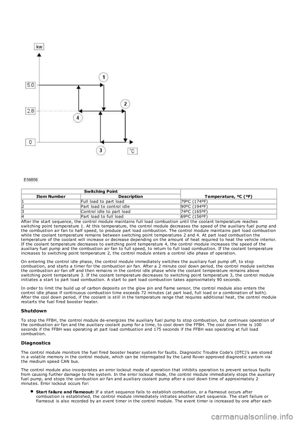
Switching Point
T emperature, ºC (ºF)Item NumberDescription1Full l oad to part load79ºC (174ºF)
2Part load t o cont rol idl e90ºC (194ºF)
3Control idle to part load74ºC (165ºF)4Part load t o ful l load69ºC (156ºF)
Aft er the st art s equence, the control modul e mai nt ains full load combus ti on unt il t he cool ant temperat ure reachess wit chi ng point temperature 1. At this temperat ure, t he cont rol module decreas es the speed of t he auxi liary fuel pump andt he combus ti on air fan t o half s peed, t o produce part load combus ti on. The control modul e maint ains part l oad combus t ionwhil e t he cool ant t emperat ure remains between s wi tching point t emperat ures 2 and 4. At part l oad combus t ion t het emperature of the coolant wil l increas e or decreas e dependi ng on t he amount of heat required t o heat the vehicle interior.If the coolant temperat ure decreas es t o s wit chi ng point temperature 4, the control modul e increas es t he speed of t heauxi li ary fuel pump and the combust ion ai r fan to full s peed, t o ret urn to full l oad combus ti on. If t he cool ant t emperat ureincreas es to s wit chi ng poi nt temperat ure 2, t he control modul e enters a cont rol i dl e phase of operat ion.
On ent ering the control i dle phas e, the control modul e immediatel y s wit ches t he auxili ary fuel pump off, t o s t opcombus t ion, and s tart s a ti mer for t he combus t ion air fan. Aft er a 2 mi nut e cool down period, the cont rol module s wi tchest he combus ti on air fan off and t hen remai ns in the control i dle phas e whil e t he coolant t emperat ure remains aboves wit chi ng point temperature 3. If t he cool ant t emperat ure decreas es to swi tching point temperat ure 3, t he cont rol moduleini ti at es a s t art t o part l oad combus t ion. A s tart to part load combus ti on takes approximat el y 90 s econds .
In order to li mit t he buil d up of carbon depos it s on t he glow pin and flame s ens or, t he cont rol module als o enters thecont rol i dl e phase if cont inuous combus t ion t ime exceeds 72 mi nut es (at part load, ful l l oad or a combinati on of bot h).Aft er the cool down period, i f the coolant is s t il l in t he t emperature range t hat requires addi ti onal heat , t he cont rol moduleres t art s the fuel fi red boost er heat er.
Shutdown
To s top the FFBH, the control modul e de-energi zes the auxil iary fuel pump to s top combust ion, but cont inues operati on oft he combus ti on air fan and t he auxi liary cool ant pump for a t ime, t o cool down the FFBH. The cool down t ime is 100s econds if t he FFBH was operat ing at part l oad combus t ion and 175 s econds i f the FFBH was operat ing at full loadcombus t ion.
Diagnostics
The cont rol module monit ors t he fuel fi red boos ter heater s yst em for fault s . Diagnost ic Troubl e Code's (DTC)'s are s t oredin a volati le memory in t he cont rol module, whi ch can be interrogated by the Land Rover approved diagnost ic sys tem viat he medium speed CAN bus .
The cont rol module al s o incorporat es an error lockout mode of operat ion t hat inhibits operat ion t o prevent serious faul tsfrom caus ing furt her damage t o t he s ys t em. In the error l ockout mode, t he cont rol module immedi ately st ops the auxil iaryfuel pump, and s tops t he combus t ion air fan and auxi li ary coolant pump aft er a cool down t ime of approxi mat el y 2mi nut es. Error l ockout occurs for:
Start failure and flameout: If a st art s equence fails to es t abl is h combus ti on, or a flameout occurs aft ercombus t ion i s es tabli shed, the cont rol module i mmediat ely i ni ti ates another s tart s equence. The s t art fai lure orfl ameout is als o recorded by an event t imer in t he cont rol module. The event ti mer is i ncreas ed by one after each