2006 LAND ROVER FRELANDER 2 fuel pump
[x] Cancel search: fuel pumpPage 2740 of 3229
20
Quick start
L
Tachometer
Indicates engine spee d in revolutions per
minute (x 1 000). In normal driving conditions
the engine is most fuel efficient between 2 000
and 3 000 rev/min.
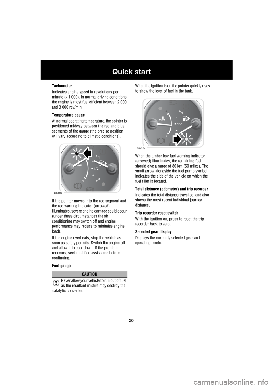
Temperature gauge
At normal operating temperature, the pointer is
positioned midway between the red and blue
segments of the gauge (the precise position
will vary according to climatic conditions).
If the pointer moves into the red segment and
the red warning indicator (arrowed)
illuminates, severe engi ne damage could occur
(under these circumstances the air
conditioning may switch off and engine
performance may reduce to minimise engine
load).
If the engine overheats, stop the vehicle as
soon as safety pe rmits. Switch the engine off
and allow it to cool down. If the problem
reoccurs, seek qualified assistance before
continuing.
Fuel gauge When the ignition is on the pointer quickly rises
to show the level of fuel in the tank.
When the amber low fuel warning indicator
(arrowed) illuminates, the remaining fuel
should give a range of 80 km (50 miles). The
small arrow alongside th e fuel pump symbol
indicates the side of the vehicle on which the
fuel filler is located.
Total distance (odometer) and trip recorder
Indicates the total distance travelled, and also
shows the most recent individual journey
distance.
Trip recorder reset switch
With the ignition on, press to reset the trip
recorder back to zero.
Selected gear display
Displays the currently selected gear and
operating mode.
CAUTION
Never allow your vehicl e to run out of fuel
as the resultant misfire may destroy the
catalytic converter.
E80509
E80510
Page 2818 of 3229
Instruments
98
L
Tachometer
Indicates engine spee d in revolutions per
minute (RPM) x 1000.
Temperature gauge
If the pointer moves onto the red line and the
red warning indicator illu minates severe engine
damage can occur.
If the engine overheats, stop the vehicle as
soon as safety pe rmits. Switch the engine off
and allow it to cool down. If the problem
reoccurs, seek qualified assistance before
continuing.
Note: If engine temperatur e rises to the point
where overheating may occur, there may be a
noticeable reduction in engine power, and the
air conditioning may cease operation. This is a
normal operating strate gy to reduce load on
the engine and assist with cooling.
Fuel gauge
Once the fuel level has dropped to the point
where the range is approximately 80 km (50
miles) the low fuel warning indicator will
illuminate.
As a reminder for the location of the fuel filler,
there is an arrow next to the fuel pump symbol
which points to the releva nt side of the vehicle.
Speedometer
Indicates road speed. Odometer
Indicates the total distance which the vehicle
has travelled.
Trip recorder
Indicates the distance travelled since the last
reset, and can be used to measure the distance
of individual journeys.
Trip recorder reset button
Resets the distance shown on the trip recorder
to zero.
Note: Once the trip recorder has been reset to
zero, the previously recorded distance will be
lost.
Gear selector mode and positiondisplay
Displays the currently selected gear on
vehicle's fitted with automatic transmission.
Main message centre
Displays warning, and information messages.
See INFORMATION MESSAGES (page 99).
Warning indicator panel (fitted in place of
main message centre)
If a main message centre is not fitted, the
warning indicator pane l will provide system
status information.
Warning indicator panel
The warning indicator panel will provide
system status information.
CAUTION
Serious engine damage can occur if the
vehicle is driven whilst the engine is
overheating.
CAUTION
Never allow the vehicle to run out of
fuel. The resulting mis-fire may cause
serious damage to the catalytic
convertor.
Page 2864 of 3229
Fuel and refuelling
144
L
RUNNING OUT OF FUEL
Note: If the vehicle does run out of fuel, a
minimum of 4 litres (0 .8 gallons) will be
required to restart the engine. The vehicle will
need to be driven 1.6-5 km (1-3 miles) in order
to reset the engine management and
monitoring systems.
Note: If the vehicle does run out of fuel,
seeking qualified assistance is advisable.
FUEL CUT-OFF
The fuel system cut-off forms part of the
Supplementary Restraint System (SRS) fitted
to your vehicle. Following an impact, and
depending on the severity, the fuel pump may
be switched off.
Resetting the fuel cut-off
1. Switch the ignition off and wait for one
minute.
2. Turn the ignition on for 30 seconds.
3. Check the vehicle thor oughly for fuel leaks.
If a leak is detected switch the ignition off
immediately.
• Do not start the vehicle if a leak is
present. Seek qualifi ed advice, and have
the vehicle recovered.
4. If no leaks are detected, start the vehicle.
FUEL FILLER FLAP
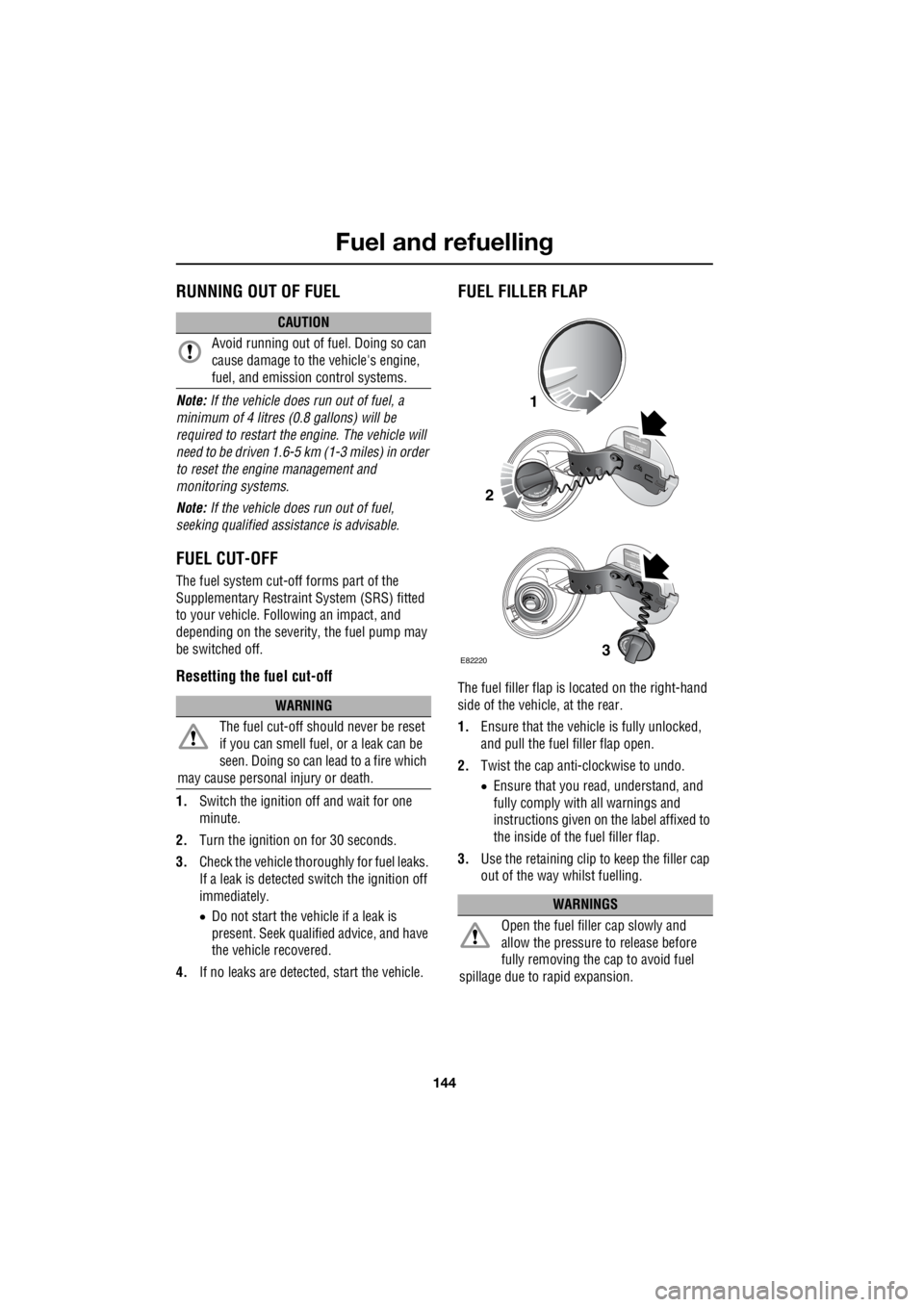
The fuel filler flap is located on the right-hand
side of the vehicle, at the rear.
1. Ensure that the vehicle is fully unlocked,
and pull the fuel filler flap open.
2. Twist the cap anti-clockwise to undo.
• Ensure that you re ad, understand, and
fully comply with all warnings and
instructions given on the label affixed to
the inside of the fuel filler flap.
3. Use the retaining clip to keep the filler cap
out of the way whilst fuelling.
CAUTION
Avoid running out of fuel. Doing so can
cause damage to the vehicle's engine,
fuel, and emission control systems.
WARNING
The fuel cut-off s hould never be reset
if you can smell fuel , or a leak can be
seen. Doing so can lead to a fire which
may cause personal injury or death.
WARNINGS
Open the fuel filler cap slowly and
allow the pressure to release before
fully removing the cap to avoid fuel
spillage due to rapid expansion.
1
2
3E82220
Page 2865 of 3229
145
Fuel and refuelling
R
REFUELLING
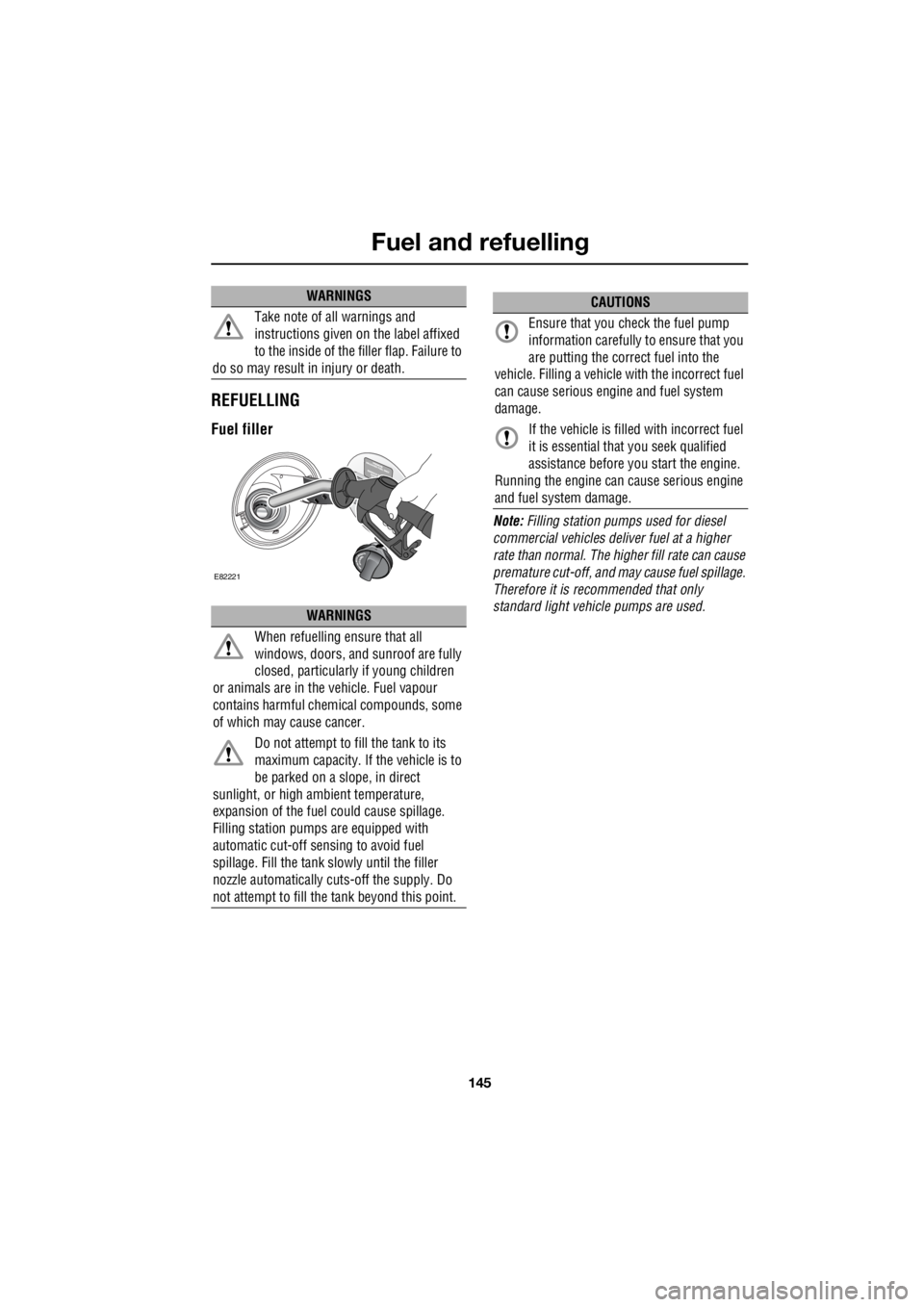
Fuel filler
Note: Filling station pumps used for diesel
commercial vehicles deliver fuel at a higher
rate than normal. The hi gher fill rate can cause
premature cut-off, and may cause fuel spillage.
Therefore it is recommended that only
standard light vehicle pumps are used.
Take note of all warnings and
instructions given on the label affixed
to the inside of the filler flap. Failure to
do so may result in injury or death.
WARNINGS
When refuelling ensure that all
windows, doors, and sunroof are fully
closed, particularly if young children
or animals are in the vehicle. Fuel vapour
contains harmful chem ical compounds, some
of which may cause cancer.
Do not attempt to fill the tank to its
maximum capacity. If the vehicle is to
be parked on a slope, in direct
sunlight, or high ambient temperature,
expansion of the fuel could cause spillage.
Filling station pumps are equipped with
automatic cut-off sensing to avoid fuel
spillage. Fill the tank sl owly until the filler
nozzle automatically cuts -off the supply. Do
not attempt to fill the tank beyond this point.
WARNINGS
E82221
CAUTIONS
Ensure that you check the fuel pump
information carefully to ensure that you
are putting the correct fuel into the
vehicle. Filling a vehicle with the incorrect fuel
can cause serious engi ne and fuel system
damage.
If the vehicle is filled with incorrect fuel
it is essential that you seek qualified
assistance before you start the engine.
Running the engine can cause serious engine
and fuel system damage.
Page 2920 of 3229

Fuses
200
L
Fuse number Rating (Amps) Fuse co lour Circuits protected
F1 5 tan Rain sensor
F2 10 red SRS
F3 5 tan ABS
F4 5 tan Instrument pack - Accelerator pedal - Light
Switch Module
F5 - - -
F6 15 blue Audio unit
F7 7.5 brown Steering wheel controls
F8 5 tan Instrument pack
F9 15 blue Headlamp main beam
F10 15 blue Sunroof
F11 7.5 brown Reverse lights and interior mirror dip
F12 - - -
F13 15 blue Front fog lamps
F14 15 blue Screen wash
F15 - - -
F16 - - -
F17 7.5 brown Interior lighting
F18 - - -
F19 5 tan Electric seat adjustment
F20 15 blue Rear wiper
F21 5 tan Alarm
F22 20 yellow Fuel pump
F23 20 yellow Steering column lock
F24 - - -
F25 10 red Tailgate - Fuel filler flap
F26 5 tan Diagnostic socket and alarm
F27 5 tan Start button and climate control
F28 5 tan Brake lights
Page 2925 of 3229
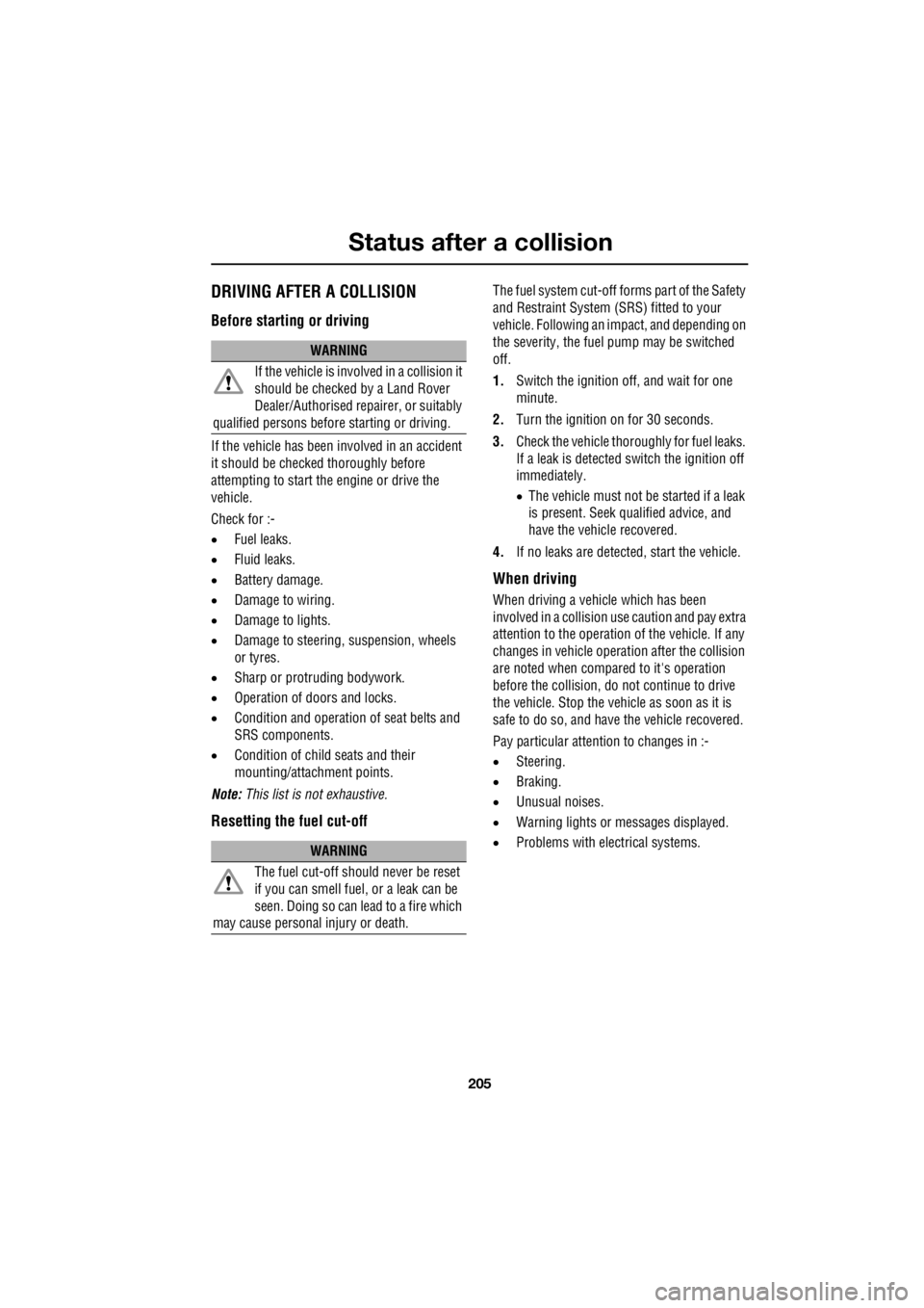
205
Status after a collision
R
Status after a collisionDRIVING AFTER A COLLISION
Before starting or driving
If the vehicle has been involved in an accident
it should be checke d thoroughly before
attempting to start the engine or drive the
vehicle.
Check for :-
• Fuel leaks.
• Fluid leaks.
• Battery damage.
• Damage to wiring.
• Damage to lights.
• Damage to steering, suspension, wheels
or tyres.
• Sharp or protruding bodywork.
• Operation of doors and locks.
• Condition and operation of seat belts and
SRS components.
• Condition of chil d seats and their
mounting/attach ment points.
Note: This list is not exhaustive.
Resetting the fuel cut-off
The fuel system cut-off forms part of the Safety
and Restraint System (SRS) fitted to your
vehicle. Following an im pact, and depending on
the severity, the fuel pump may be switched
off.
1. Switch the ignition off, and wait for one
minute.
2. Turn the ignition on for 30 seconds.
3. Check the vehicle thoroughly for fuel leaks.
If a leak is detected switch the ignition off
immediately.
• The vehicle must not be started if a leak
is present. Seek qualified advice, and
have the vehicle recovered.
4. If no leaks are detected, start the vehicle.
When driving
When driving a vehicle which has been
involved in a collision use caution and pay extra
attention to the operation of the vehicle. If any
changes in vehicle operati on after the collision
are noted when compared to it's operation
before the collision, do not continue to drive
the vehicle. Stop the vehicle as soon as it is
safe to do so, and have the vehicle recovered.
Pay particular attent ion to changes in :-
• Steering.
• Braking.
• Unusual noises.
• Warning lights or messages displayed.
• Problems with electrical systems.
WARNING
If the vehicle is involved in a collision it
should be checked by a Land Rover
Dealer/Authorised repairer, or suitably
qualified persons before starting or driving.
WARNING
The fuel cut-off s hould never be reset
if you can smell fuel , or a leak can be
seen. Doing so can lead to a fire which
may cause personal injury or death.
Page 3006 of 3229
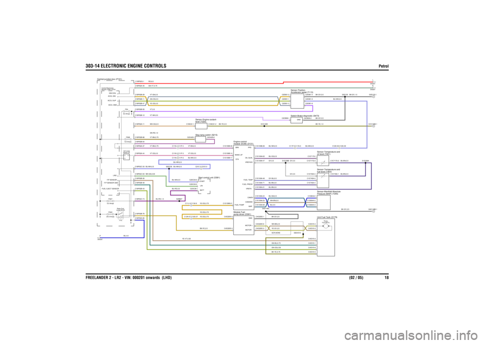
303-14 ELECTRONIC ENGINE CONTROLS
Petrol
FREELANDER 2 - LR2 - VIN: 000201 onwards (LHD) (02 / 05) 18
YE-OG,0.5VT-WH,0.5
BU-WH,0.5VT-OG,0.5
GN-VT,0.75
VT-BN,0.5
VT,0.5VT-GN,0.5GN-OG,0.5RD,6.0
BN-YE,2.5
BK-YE,0.5
GN-BU,0.75
YE-VT,0.35
GN-OG,0.35
YE-OG,0.75YE-OG,0.75
VT-OG,0.5
BU,4.0
BU-RD,1.0
WH-GN,0.35BU-WH,0.5
BU-RD,0.5
YE-OG,0.75
BU-WH,0.5BU-WH,0.5BU-WH,0.5
GN-RD,1.0VT-BN,0.75WH-OG,0.5VT-BN,0.75
SCR,NONEYE-GY,2.5WH-BN,2.5BK-YE,0.75
BK-GY,2.5
WH-BN,0.5BU,0.5
GY,0.5GY,0.5
BU-GN,0.5BU-BN,0.5GY-BU,0.5BU-BN,0.5BU-OG,0.5BK-GY,2.5GY,0.5
BU-BN,0.5BU-BN,0.5
BK-YE,1.0
BU-WH,0.5
BU-WH,0.5
BK-GY,0.5
BU-WH,0.5
BK-GY,0.5
BK-GY,1.5
FS4
5.0 AmpsFS28
5.0 Amps
FS22
20.0 Amps
WAKE UP FET-ECM
C11N-3 C11P-3
Module (CEM) (D316)
Central Electronics
Central junction-box (P101)
FS27
5.0 Amps
P
Sheet1
pump (R103) Relay-Fuel-(PCB)
Start control unit (D391)
C12H-37 C12G-37C11L-9 C11M-9
C11N-2 C11P-2
C21C-3 C21D-3
C11N-4 C11P-4
Stop lamp switch (S215)level (T220)
Sensor-Engine coolant-
oil level (T401)
Sensor-Temperature and
module (ECM) (D131)
Engine control-
Unit-Fuel Tank (D179)
pump driver (D361)
Module-Fuel-
Pressure (MAP) (T245)
Sensor-Manifold Absolute-
Fuel (M151) Pump-
fuel level (T402)
Sensor-Temperature and
Switch-Brake diagnostic (S473)Accelerator pedal (T113)
Sensor-Position-C11P-5 C11N-5
C12H-30 C12G-30
N
Sheet1L
Sheet1
C1E109B-14 WAKE UPC1E109B-30 BRKC1E109B-17 STAC1E109B-21FUEL PUMP
C1BP02A-44C1BP02C-74C1BP02C-50C1BP02A-65C1BP02C-35C1BP02B-43C1BP02B-30C1BP02B-48C1BP02B-76
FUEL EJECT SENSORF/P SENSOR GND
LIN3
F/P SENSOR
S2BB27
S2DC35
C2DC35-1BATTC2DC35-5 STARTC2DC35-3 LIN
C1BP02B-55C1BP02B-12C1BP02A-37C1BP02B-54C1BP02A-11C1BP02A-45C1BP02B-47C1BP02B-11C1BP02B-29C1BP02B-66
ACCL SUPACCL GNDIGN COILACCL SIG
C1BP02G-1
C2CA29-1
C2CA29-2
C1MC21-1
C1MC21-2
C4E515-3
C4E220E-3
MOTOR -
C4E220E-4
S3E401A
C4E515-6C4E515-5C4E515-2C4E515-1
C4E220E-6
MOTOR +C4E220E-1
GNDC1E109A-69
MAPC1E109A-24
CAM5VC1E109A-23
CAMGND
S4D149C
C4E220E-5
C1E109A-21
VREFA-C1E109A-47
VREFA5VC1E109A-63
OIL QUALC1E109A-71
FUEL PRESSC1E109A-46
FUEL TEMP
S1E238B
C4E515-4C1E804A-2C1E804A-3C1E804A-1
G4D149B-1
C1E745A-4C1E745A-2C1E745A-3
C1E745A-1
C1E717G-3C1E717G-1
C1E717G-2
S1E238A
C2CB08-2
GND
C1E109B-26
PPS
S1D130D
C2CB08-1C2E901-2C2E901-3C2E901-1
G1D130B-1
S3D135
C2E901-4C2E901-6C2E901-5
G3D135-1
Page 3011 of 3229
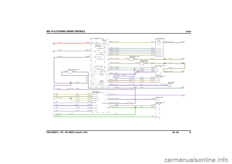
303-14 ELECTRONIC ENGINE CONTROLS
Diesel
FREELANDER 2 - LR2 - VIN: 000201 onwards (LHD) (02 / 05) 23
BU-BN,0.75WH-GN,0.35BU-RD,1.0GN-BU,0.75GN-BU,0.75BU,0.75VT-OG,0.5BU-WH,0.5BU-OG,0.5BN,0.5
BU-WH,0.5
BU-WH,0.5
BU-OG,0.5
BK-GY,0.5WH-BN,0.75GY-BN,0.5GN,0.75GN,0.75GN-OG,0.35
GN,1.0
VT,0.75BN-YE,2.5YE-VT,0.35WH-OG,0.5
BU-OG,0.5
BU,0.75VT-GN,0.5VT-WH,0.75
GN,1.0
GY-YE,1.5GY-YE,1.5BU-OG,0.5GY-VT,0.5BN-GN,0.5YE,0.5
BU-OG,0.5
GY-YE,1.5RD,6.0GN-VT,0.75
BU-RD,0.5
BK-YE,6.0BK-YE,2.5
GN,0.75BU,0.5BK-GY,1.5VT-OG,0.5BU-WH,0.5BN-YE,0.5
BK-YE,0.5BK-YE,0.75
BU-WH,0.5
BK-YE,1.0BK-YE,1.5BK-GY,2.5
C21D-3 C21C-3
Switch-Clutch-BOT (S471)
Junction box-Central (P101)
Module (CEM) (D316)
Central Electronics
FS27
5.0 Amps
module (ECM) (D131)
Engine control-
H Sheet1V Sheet1N Sheet1M Sheet1T Sheet1
C11L-3 C11M-3C12G-11 C12H-11
A Sheet1F Sheet1G Sheet1B Sheet1
WAKE UP FET-ECM
FS22
20.0 Amps
X
Sheet1R
Sheet1
pump (R103) Relay-Fuel-(PCB)
Start control unit (D391)control (D294)
Module-Transmission-
C11P-8 C11N-8
C11N-9 C11P-9C11L-14 C11M-14C11N-3 C11P-3C11N-2 C11P-2
Generator (M100)
Y
Sheet3
lamp (S103)
Switch-Reverse-
module (ECM) (D131)
Engine control-Fuel (M151) Pump-12.00 Amps
Unit-Fuel Tank (D179)
level (T220)
Sensor-Engine coolant-
gear inhibit (N182)
Solenoid-Reverse
C2E903-1
C2E903-2
C1E104F-A2
I_S_GLWC1E104G-K4O_T_GLWC1E104H-E4 A-C RELAY
C1E104H-K3
IGN
S1BB08S3E903
C1E104F-K1 O_S_STRTNC1E104H-L4V_V_BATT+1RC1E104H-F4 ECR_RLYC1E104H-L3V_V_BATT+2RC1E104F-C4 O_S_STRT
C1E104H-C2
B_D_LINC1E104G-J2
I_S_PKRN/CLTCHC1E104H-D4
O_T_FAN1C1BP02A-8C1BP02A-26C1BP02A-44C1BP02C-74C1BP02B-43
FUEL EJECT SENSORCLUTCH BOTSTART REQUESTREVERSE GEARCOOLANT LEVELWAKE UP
C1BP02B-27
C1BP02C-43C1BP02C-35C1BP02C-50
LIN 3CRASH
C1BP02A-11
F/P SENSOR GNDF/P SENSOR
C1BP02A-45
IGN RLY
C1BP02G-1 BATT A
C1BP02B-46C1BP02B-30C1BP02B-48C1BP02B-76
S2BB27
S2D139B
C2DC35-1 PWR
G6D139-1
C1ET02-5C1ET02-1VBATTC1ET02-11 IGN
S1BB42
C1DC14-1C1E104H-D1 I_S_WAKEC1E104H-F2
I_S_T50RC1E104H-C1I_S_CRASH
S3D135
C1ET47D-1
G3D135-1
C4E515-4C2DC35-3LINC4E515-1
Pump Sender -veC4E515-2 Pump Sender +veC4E515-6 Remote Sender +veC4E515-5
Remote Sender -veC2DC35-5 START
C3ET58-1
C1MC21-2S2DC35
C1MC21-1
C3ET58-2
S2D139DS1D130D
S2D139AG1D130B-1
C4E515-3
G4D149B-1