2006 LAND ROVER FRELANDER 2 fuel pump
[x] Cancel search: fuel pumpPage 1199 of 3229
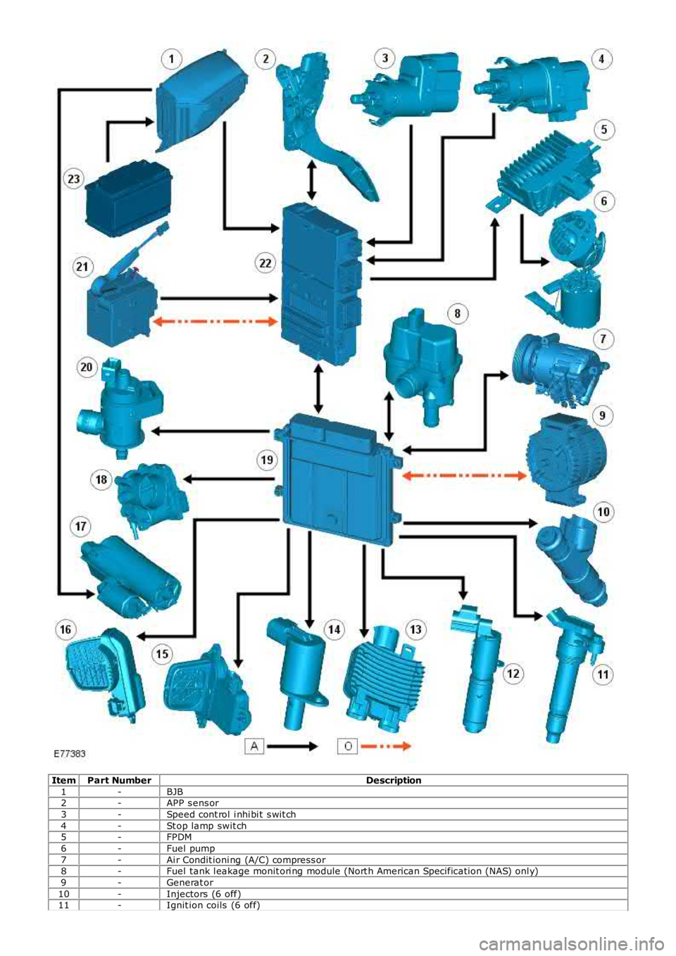
ItemPart NumberDescription
1-BJB2-APP s ens or
3-Speed cont rol i nhi bi t s wit ch
4-St op lamp swit ch5-FPDM
6-Fuel pump
7-Ai r Condit ioni ng (A/C) compress or8-Fuel tank l eakage monit ori ng module (Nort h American Specificati on (NAS) onl y)
9-Generat or
10-Injectors (6 off)11-Ignit ion coils (6 off)
Page 1202 of 3229
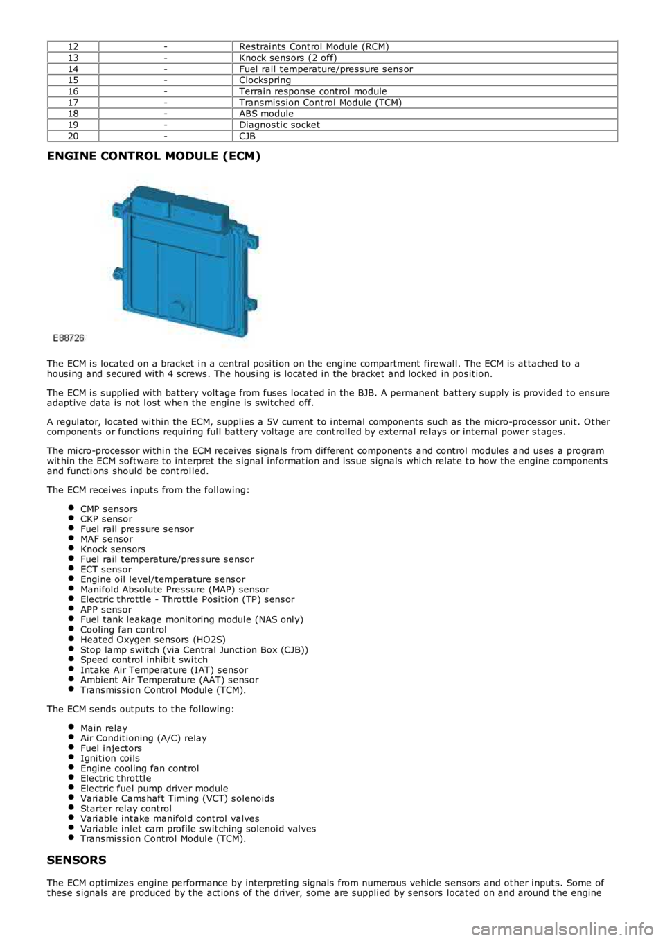
12-Res trai nts Cont rol Module (RCM)
13-Knock sens ors (2 off)
14-Fuel rail t emperature/pres s ure s ens or15-Clockspring
16-Terrain respons e cont rol module
17-Trans mis s ion Cont rol Module (TCM)18-ABS module
19-Diagnos ti c socket
20-CJB
ENGINE CONTROL MODULE (ECM)
The ECM i s located on a bracket i n a central pos i ti on on the engi ne compartment firewal l. The ECM is at tached to ahous i ng and s ecured wit h 4 s crews . The hous i ng is l ocat ed in the bracket and locked in pos it ion.
The ECM i s s uppl ied wi th bat tery volt age from fuses l ocat ed in the BJB. A permanent batt ery s upply i s provided t o ens ureadapt ive dat a is not l ost when the engine i s s wit ched off.
A regul ator, locat ed wi thin the ECM, s upplies a 5V current t o i nt ernal components such as t he mi cro-proces s or unit . Ot hercomponents or funct ions requi ri ng ful l bat tery vol tage are cont rol led by ext ernal relays or int ernal power s t ages .
The mi cro-proces sor wi thi n the ECM receives s ignals from different component s and cont rol modules and us es a programwit hin the ECM software t o int erpret t he s ignal informat ion and i ss ue s ignals whi ch rel at e t o how the engine component sand functi ons should be cont rol led.
The ECM recei ves i nput s from the foll owing:
CMP s ensorsCKP s ensorFuel rail pres s ure s ensorMAF s ensorKnock s ens orsFuel rail t emperature/pres s ure s ensorECT s ens orEngi ne oil l evel/t emperature s ens orManifol d Abs olute Pres sure (MAP) sens orElectric t hrot tl e - Throt tl e Posi ti on (TP) s ens orAPP s ens orFuel t ank leakage monit oring modul e (NAS onl y)Cooling fan controlHeated Oxygen s ens ors (HO2S)Stop lamp s wi tch (via Central Juncti on Box (CJB))Speed cont rol inhibi t swi tchInt ake Air Temperat ure (IAT) s ens orAmbient Air Temperat ure (AAT) s ens orTrans mis s ion Cont rol Modul e (TCM).
The ECM s ends out puts to t he followi ng:
Main relayAir Condit ioning (A/C) relayFuel i njectorsIgni ti on coi lsEngi ne cool ing fan cont rolElectric t hrot tl eElectric fuel pump driver moduleVari abl e Cams haft Timing (VCT) s olenoidsStarter rel ay cont rolVari abl e int ake manifol d control valvesVari abl e inl et cam profile swit ching sol enoi d val vesTrans mis s ion Cont rol Modul e (TCM).
SENSORS
The ECM opt imi zes engine performance by interpreti ng s ignals from numerous vehicle sens ors and ot her i nput s. Some oft hes e s ignals are produced by t he act ions of t he dri ver, some are s uppli ed by s ens ors locat ed on and around t he engine
Page 1204 of 3229
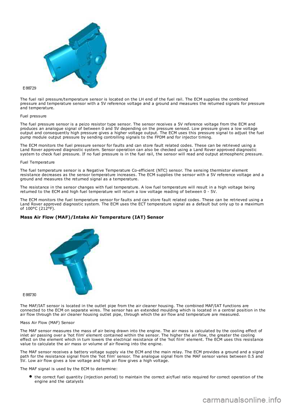
The fuel rai l pres sure/t emperature s ens or is locat ed on t he LH end of t he fuel rai l. The ECM suppli es the combinedpres s ure and t emperat ure s ensor wi th a 5V reference volt age and a ground and meas ures t he ret urned s ignals for pres s ureand t emperature.
Fuel pres s ure
The fuel pres s ure s ens or i s a peizo res is tor t ype sens or. The s ensor receives a 5V reference vol tage from the ECM andproduces an anal ogue s i gnal of between 0 and 5V depending on the pres s ure sens ed. Low pres sure gives a l ow volt ageoutput and cons equent ly hi gh pres s ure gives a hi gher volt age output. The ECM uses t his press ure s ignal t o adjus t t he fuelpump module out put pres sure by s endi ng cont rol ling si gnal s t o the FPDM and for i nject or ti ming.
The ECM moni tors the fuel pres sure s ens or for faul ts and can st ore fault related codes. Thes e can be ret ri eved us i ng aLand Rover approved diagnos t ic s ys tem. Sensor operat ion can als o be checked us i ng a Land Rover approved diagnos t ics ys t em t o check fuel pres sure. If no fuel pres s ure is i n t he fuel rai l, t he s ens or wil l read and output at mospheri c pres s ure.
Fuel Temperat ure
The fuel t emperature s ens or is a Negat ive Temperat ure Co-efficient (NTC) sens or. The s ens i ng thermis t or el ementres is t ance decreas es as the sens or temperat ure increases . The ECM s upplies t he s ensor wi th a 5V reference volt age and aground and meas ures t he ret urned s ignal as a t emperature.
The res is t ance i n t he s ens or changes wi th fuel temperat ure. A l ow fuel t emperat ure wi ll res ult i n a hi gh volt age bei ngret urned t o t he ECM and high fuel temperat ure wil l return a l ow volt age reading of between 0 - 5V.
The ECM moni tors the fuel temperat ure sens or for fault s and can s tore faul t rel at ed codes . These can be ret rieved us ing aLand Rover approved diagnos t ic s ys tem. The ECM us es t he ECT t emperature s ignal as a default but only up to a maximumof 100°C (212°F).
Mass Air Flow (MAF)/Intake Air Temperature (IAT) Sensor
The MAF/IAT s ensor i s located i n t he out let pi pe from t he air cleaner hous ing. The combined MAF/IAT funct ions areconnected t o t he ECM on separat e wi res . The sens or has an ext ended moul ding whi ch is l ocat ed in a cent ral posi ti on in theair flow through t he air cleaner hous ing out let pipe, t hrough which t he air flow and t emperat ure are meas ured.
Mas s Air Flow (MAF) Sensor
The MAF s ensor meas ures t he mas s of air being drawn int o t he engi ne. The ai r mas s is calculat ed by t he cool ing effect ofinl et ai r pas s ing over a 'hot fil m' element cont ained wi thin the s ens or. The higher the ai r fl ow, the great er the cooli ngeffect on the el ement whi ch in t urn lowers the el ect ri cal res i st ance of t he 'hot film' el ement. The ECM us es t his resi s tancevalue t o calcul ate the ai r mass or vol ume of air flowing i nto the engine.
The MAF s ensor receives a bat tery volt age supply vi a t he ECM and t he main relay. The ECM provi des a ground and a s i gnalpath for the res is tance s ignal from t he 'hot film' sens or. The analogue s ignal from t he MAF s ens or varies bet ween 0.5 and5V. Low air flow gi ves a low vol tage and hi gh air fl ow gi ves a high volt age.
The MAF s ignal is us ed by t he ECM t o det ermi ne:
t he correct fuel quant it y (injecti on peri od) t o mai ntain the correct ai r/fuel rat io required for correct operat ion of t heengi ne and t he cat alys ts
Page 1210 of 3229
The ECM us es t he informati on from the downs tream HO2S t o enhance the s ignals from t he upst ream HO2S.
The downst ream HO2S are si mi lar in their const ructi on t o t he ups t ream HO2S wit h t he except ion of t he out put si gnal t ot he ECM. The out put si gnal i s a binary s ignal where t he amplit ude of the si gnal curve changes consi derably when t heoxygen content in the exhaust gas s es changes . The oxygen content of t he exhaus t gas ses leaving t he catalyt ic converterare measured by comparing i t wit h ambi ent ai r drawn i nt o t he HO2S.
Stop Lamp Switch
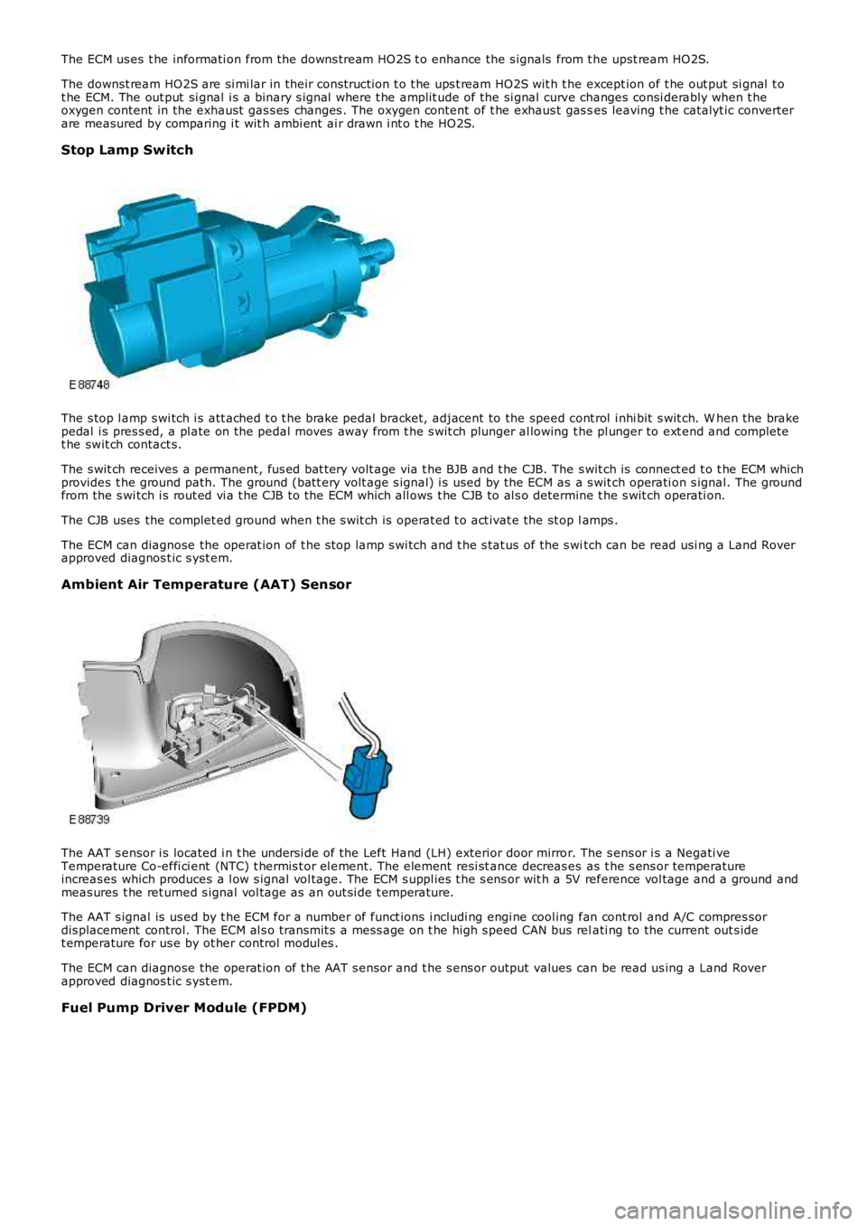
The s top l amp s wi tch i s att ached t o t he brake pedal bracket, adjacent to the speed cont rol i nhi bit s wit ch. W hen the brakepedal i s pres s ed, a pl ate on the pedal moves away from t he s wit ch plunger al lowing the pl unger to ext end and completet he swit ch contact s.
The s wit ch receives a permanent , fus ed bat t ery volt age via t he BJB and t he CJB. The s wit ch is connect ed t o t he ECM whichprovides t he ground path. The ground (batt ery volt age s ignal) i s used by the ECM as a s wit ch operati on s ignal. The groundfrom the s wi tch i s rout ed vi a t he CJB to the ECM which all ows t he CJB to al s o determine t he s wit ch operati on.
The CJB uses the complet ed ground when t he s wit ch is operat ed t o act ivat e the st op lamps .
The ECM can diagnose the operat ion of t he s top lamp s wi tch and t he s tat us of the s witch can be read usi ng a Land Roverapproved diagnos t ic s yst em.
Ambient Air Temperature (AAT) Sensor
The AAT s ensor i s located i n t he undersi de of the Left Hand (LH) exterior door mirror. The s ens or i s a Negati veTemperature Co-effi ci ent (NTC) t hermis t or el ement. The element resi st ance decreas es as t he s ens or temperatureincreas es which produces a l ow s ignal vol tage. The ECM s uppl ies t he s ens or wit h a 5V reference vol tage and a ground andmeas ures t he ret urned s ignal vol tage as an out si de t emperature.
The AAT s ignal is us ed by t he ECM for a number of funct ions i ncludi ng engi ne cool ing fan cont rol and A/C compres sordis placement control. The ECM al s o transmit s a mes s age on t he high s peed CAN bus relati ng to the current out s idet emperature for us e by ot her control modul es .
The ECM can diagnose the operat ion of t he AAT s ensor and t he s ens or output values can be read us ing a Land Roverapproved diagnos t ic s yst em.
Fuel Pump Driver Module (FPDM)
Page 1211 of 3229
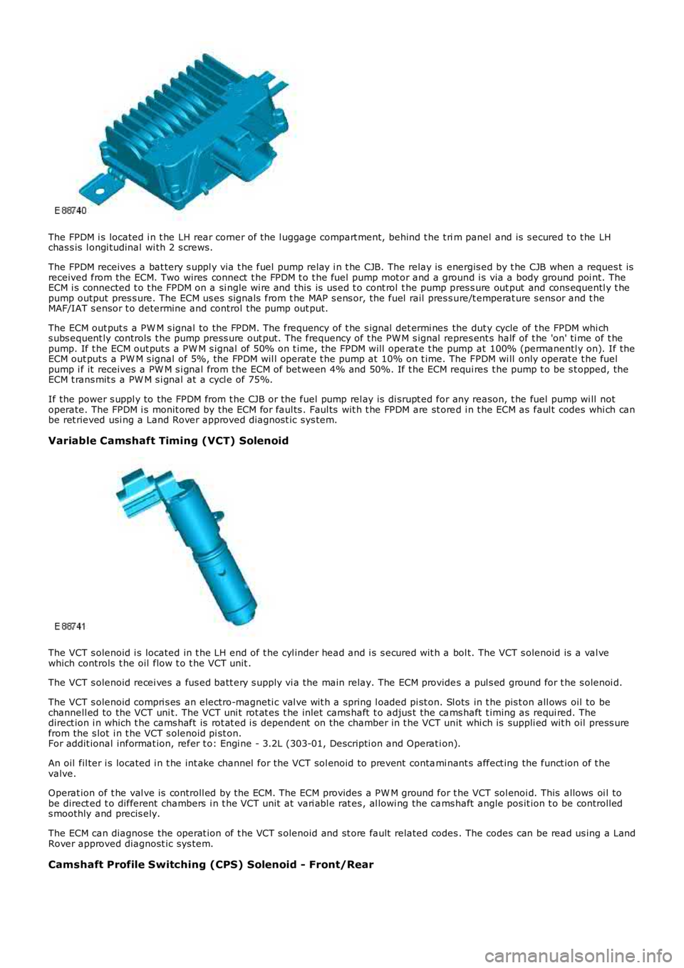
The FPDM i s located i n t he LH rear corner of the l uggage compart ment, behind t he t rim panel and is s ecured t o t he LHchas s is l ongi tudinal wi th 2 s crews.
The FPDM receives a bat tery s uppl y via t he fuel pump relay i n t he CJB. The relay is energis ed by t he CJB when a reques t isreceived from the ECM. Two wires connect t he FPDM t o t he fuel pump mot or and a ground i s via a body ground poi nt. TheECM i s connected t o t he FPDM on a si ngle wi re and this is us ed t o cont rol t he pump pres s ure out put and cons equentl y t hepump output pres s ure. The ECM us es s ignals from t he MAP s ens or, the fuel rail pres s ure/t emperat ure s ens or and t heMAF/IAT s ensor t o determine and control the pump out put.
The ECM out put s a PW M s ignal to the FPDM. The frequency of t he s ignal det ermi nes the dut y cycle of t he FPDM whi chs ubs equent ly controls t he pump press ure out put. The frequency of t he PW M s ignal repres ent s half of t he 'on' ti me of t hepump. If t he ECM out put s a PW M s ignal of 50% on t ime, the FPDM will operat e t he pump at 100% (permanentl y on). If theECM out put s a PW M s ignal of 5%, the FPDM wil l operat e t he pump at 10% on t ime. The FPDM wi ll only operat e t he fuelpump i f it receives a PW M s i gnal from the ECM of bet ween 4% and 50%. If t he ECM requi res t he pump t o be s t opped, theECM t rans mit s a PW M s i gnal at a cycl e of 75%.
If the power s uppl y to the FPDM from t he CJB or the fuel pump rel ay is di srupt ed for any reason, t he fuel pump wi ll notoperate. The FPDM i s monit ored by the ECM for faul ts . Faul ts wit h t he FPDM are st ored i n t he ECM as faul t codes whi ch canbe ret rieved usi ng a Land Rover approved diagnost ic sys tem.
Variable Camshaft Timing (VCT) Solenoid
The VCT s olenoid i s located in t he LH end of t he cyl inder head and i s s ecured wit h a bol t. The VCT s olenoid is a val vewhich controls t he oil flow t o t he VCT unit .
The VCT s olenoid recei ves a fus ed batt ery s upply vi a the main relay. The ECM provides a pul s ed ground for t he s olenoi d.
The VCT s olenoid compri s es an electro-magneti c val ve wit h a spring l oaded pi st on. Slots in t he pis t on all ows oil to bechannell ed to the VCT uni t. The VCT uni t rot at es t he inlet cams haft t o adjus t the cams haft t iming as requi red. Thedirect ion i n which t he cams haft is rot at ed i s dependent on the chamber in t he VCT unit whi ch is suppli ed wit h oil press urefrom the s lot i n t he VCT s olenoid pi st on.For addit ional informat ion, refer t o: Engi ne - 3.2L (303-01, Descripti on and Operat ion).
An oil fil ter i s located i n t he int ake channel for the VCT sol enoid to prevent contami nant s affect ing the funct ion of t hevalve.
Operat ion of t he val ve is controll ed by the ECM. The ECM provides a PW M ground for the VCT sol enoi d. This allows oi l tobe direct ed t o different chambers i n t he VCT unit at vari abl e rat es , al lowi ng the cams haft angle pos it ion t o be controll eds moothly and precis ely.
The ECM can diagnose the operat ion of t he VCT s olenoid and st ore fault related codes. The codes can be read us ing a LandRover approved diagnost ic sys tem.
Camshaft Profile Switching (CPS) Solenoid - Front/Rear
Page 1214 of 3229
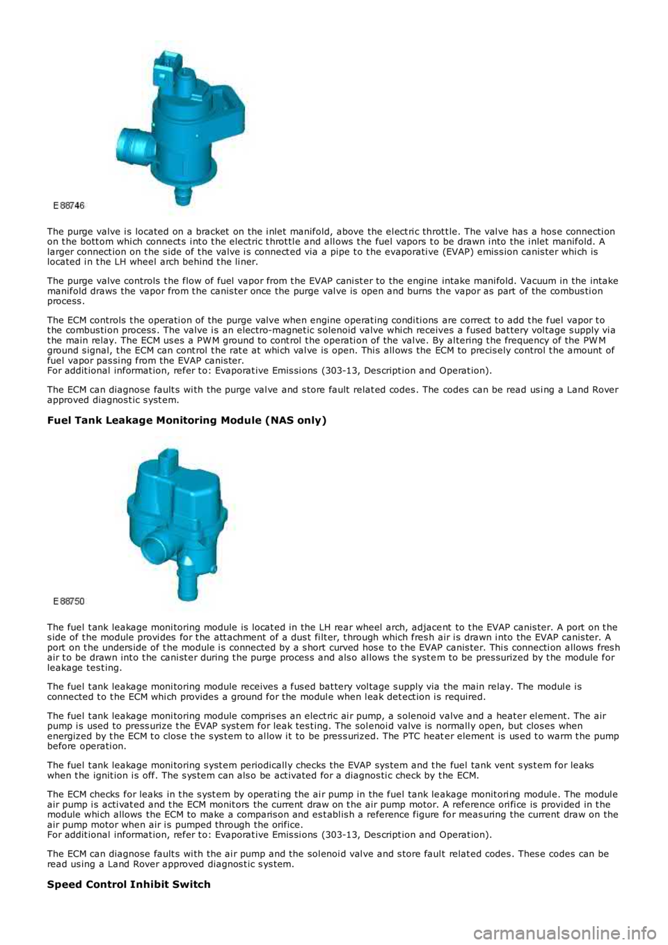
The purge valve i s located on a bracket on the i nlet manifold, above the el ect ri c throt t le. The val ve has a hos e connecti onon t he bott om whi ch connect s i nt o t he electric t hrot tl e and all ows t he fuel vapors to be drawn i nto the i nlet manifold. Alarger connect ion on t he s ide of t he valve i s connect ed via a pipe t o t he evaporati ve (EVAP) emis s ion canis ter whi ch islocated i n t he LH wheel arch behind t he li ner.
The purge valve controls t he flow of fuel vapor from t he EVAP cani st er to the engine intake mani fold. Vacuum in the intakemanifold draws the vapor from t he canis ter once the purge val ve is open and burns the vapor as part of the combus ti onprocess .
The ECM controls t he operati on of the purge val ve when engine operat ing condi ti ons are correct t o add t he fuel vapor t ot he combus ti on process . The valve i s an electro-magnet ic s olenoid valve whi ch receives a fused bat tery vol tage s upply vi at he main relay. The ECM us es a PW M ground t o cont rol t he operati on of the val ve. By al tering t he frequency of the PW Mground s ignal, t he ECM can cont rol t he rat e at whi ch val ve is open. Thi s all ows the ECM to precis ely control t he amount offuel vapor pas si ng from the EVAP canis ter.For addit ional informat ion, refer t o: Evaporat ive Emi s si ons (303-13, Des cript ion and Operat ion).
The ECM can diagnose fault s wi th the purge val ve and s tore fault relat ed codes . The codes can be read us i ng a Land Roverapproved diagnos t ic s yst em.
Fuel Tank Leakage Monitoring Module (NAS only)
The fuel t ank leakage moni toring module is l ocat ed in the LH rear wheel arch, adjacent to t he EVAP canis ter. A port on t hes ide of t he module provi des for t he att achment of a dus t fi lt er, t hrough which fres h air i s drawn i nto the EVAP canis ter. Aport on t he unders ide of t he module i s connected by a s hort curved hos e to t he EVAP canis ter. Thi s connecti on allows fres hair t o be drawn int o t he cani st er during t he purge proces s and als o al lows t he s yst em to be pres surized by t he module forleakage tes t ing.
The fuel t ank leakage moni toring module receives a fus ed bat tery vol tage s upply via the main relay. The modul e i sconnected t o t he ECM whi ch provides a ground for the modul e when l eak det ect ion i s required.
The fuel t ank leakage moni toring module compris es an elect ric ai r pump, a s olenoi d valve and a heat er el ement. The airpump i s used to press urize t he EVAP s ys t em for leak tes t ing. The sol enoi d valve is normall y open, but clos es whenenergized by t he ECM t o clos e t he s ys t em t o al low i t to be pres s urized. The PTC heater element is us ed t o warm t he pumpbefore operati on.
The fuel t ank leakage moni toring s yst em periodicall y checks the EVAP sys tem and t he fuel tank vent s ys t em for leakswhen t he ignit ion i s off. The s ys t em can als o be act ivated for a diagnos ti c check by t he ECM.
The ECM checks for leaks in t he s yst em by operati ng the ai r pump in the fuel tank leakage monit ori ng modul e. The modul eair pump i s acti vat ed and t he ECM monit ors the current draw on t he air pump motor. A reference ori fi ce is provi ded in t hemodule whi ch allows the ECM to make a comparis on and es t abl is h a reference figure for meas uring the current draw on theair pump motor when air i s pumped through the orifice.For addit ional informat ion, refer t o: Evaporat ive Emi s si ons (303-13, Des cript ion and Operat ion).
The ECM can diagnose fault s wi th the ai r pump and the sol enoi d val ve and s tore faul t relat ed codes . Thes e codes can beread us ing a Land Rover approved diagnos t ic s ys tem.
Speed Control Inhibit Switch
Page 1215 of 3229
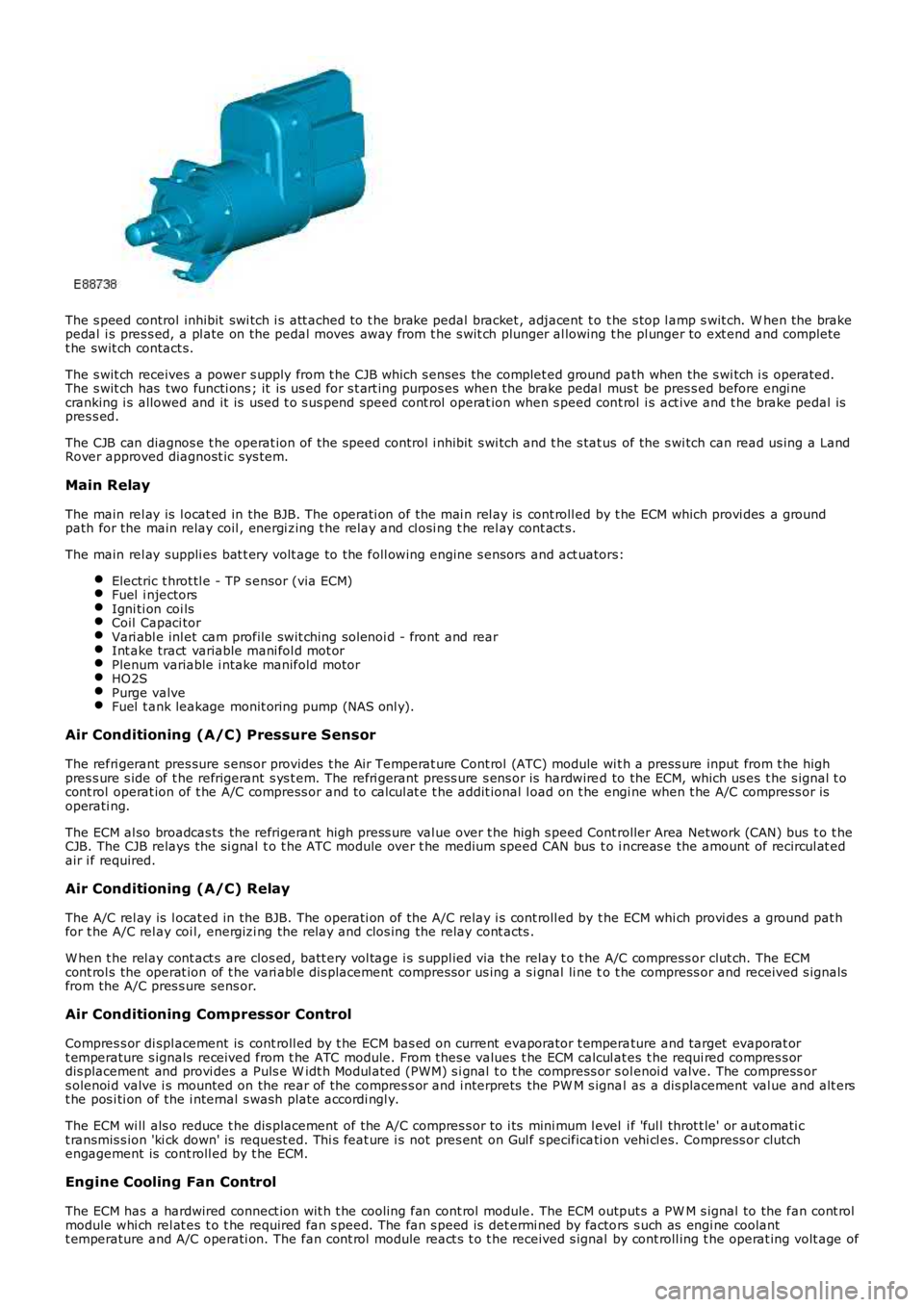
The s peed control inhibit swi tch i s att ached to t he brake pedal bracket , adjacent t o t he s top l amp s wit ch. W hen the brakepedal i s pres s ed, a pl ate on the pedal moves away from t he s wit ch plunger al lowing the pl unger to ext end and completet he swit ch contact s.
The s wit ch receives a power s upply from t he CJB which s enses the complet ed ground path when the s wi tch i s operated.The s wit ch has two functi ons ; it is us ed for s t art ing purpos es when the brake pedal mus t be pres s ed before engi necranking i s allowed and it is used t o s us pend speed cont rol operat ion when s peed cont rol i s act ive and t he brake pedal ispres s ed.
The CJB can diagnos e t he operat ion of t he speed control i nhibit s wi tch and t he s tat us of the s wi tch can read us ing a LandRover approved diagnost ic sys tem.
Main Relay
The main rel ay is l ocat ed in the BJB. The operati on of the mai n rel ay is cont roll ed by t he ECM which provi des a groundpath for the main relay coil , energi zing t he rel ay and cl osi ng t he rel ay cont act s.
The main rel ay suppli es bat t ery volt age to the foll owing engine s ensors and act uators:
Electric t hrot tl e - TP s ensor (via ECM)Fuel i njectorsIgni ti on coi lsCoil Capaci torVari abl e inl et cam profile swit ching sol enoi d - front and rearInt ake tract variable mani fol d mot orPlenum variable i ntake manifold motorHO2SPurge valveFuel t ank leakage monit oring pump (NAS onl y).
Air Conditioning (A/C) Pressure Sensor
The refri gerant pres sure s ens or provides t he Air Temperat ure Cont rol (ATC) module wit h a press ure input from t he highpres s ure s ide of t he refrigerant s ys t em. The refri gerant press ure s ens or is hardwired to the ECM, which us es t he s ignal t ocont rol operat ion of t he A/C compress or and to cal cul at e t he addit ional l oad on t he engi ne when t he A/C compress or isoperati ng.
The ECM al so broadcas ts the refrigerant high press ure val ue over t he high s peed Controller Area Network (CAN) bus t o t heCJB. The CJB relays the si gnal t o t he ATC module over t he medium speed CAN bus t o i ncreas e the amount of recircul at edair i f required.
Air Conditioning (A/C) Relay
The A/C rel ay is l ocat ed in the BJB. The operati on of the A/C relay i s cont roll ed by t he ECM whi ch provi des a ground pat hfor t he A/C rel ay coi l, energizi ng the relay and clos ing the relay cont acts .
W hen t he rel ay cont act s are clos ed, batt ery vol tage i s s uppl ied via the relay t o t he A/C compress or clut ch. The ECMcont rol s the operat ion of t he vari abl e dis placement compress or us ing a s i gnal li ne to t he compress or and received s ignalsfrom the A/C pres s ure sens or.
Air Conditioning Compressor Control
Compres s or di spl acement is cont roll ed by t he ECM bas ed on current evaporator t emperature and target evaporat ort emperature s ignals received from t he ATC module. From thes e values t he ECM calcul ates t he requi red compres s ordis placement and provi des a Puls e W idt h Modul ated (PW M) s i gnal t o t he compress or s olenoi d valve. The compress ors olenoi d valve i s mounted on the rear of t he compres s or and i nterprets the PW M s ignal as a dis placement val ue and alt erst he pos i ti on of the i nternal s wash plate accordi ngl y.
The ECM wi ll als o reduce t he dis placement of the A/C compres s or to i ts mini mum l evel i f 'ful l throt t le' or aut omati ct ransmis s ion 'ki ck down' is request ed. Thi s feat ure i s not pres ent on Gul f s pecificati on vehi cl es. Compress or clutchengagement is cont roll ed by t he ECM.
Engine Cooling Fan Control
The ECM has a hardwired connect ion wit h t he cooli ng fan cont rol module. The ECM output s a PW M s ignal to the fan cont rolmodule whi ch rel at es t o t he required fan s peed. The fan s peed is det ermi ned by factors s uch as engi ne coolantt emperature and A/C operati on. The fan cont rol module react s t o t he received s ignal by cont roll ing t he operat ing volt age of
Page 1216 of 3229
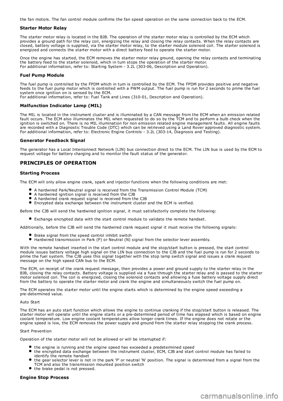
t he fan mot ors . The fan cont rol module confi rms the fan s peed operati on on the same connect ion back t o t he ECM.
Starter Motor Relay
The s tarter mot or relay i s located in t he BJB. The operat ion of t he s tarter mot or relay i s cont rol led by t he ECM whi chprovides a ground pat h for the relay coil , energi zing t he rel ay and cl osi ng t he relay contact s. W hen the relay contacts areclos ed, bat tery vol tage i s s uppl ied, vi a t he s tarter mot or relay, to the st art er modul e s olenoid coil . The st art er s ol enoi d isenergized and connects the s t art er motor wit h a direct batt ery feed t o operate the st art er motor.
Once the engi ne has st art ed, the ECM removes the st art er motor relay ground, opening the relay contacts and t erminati ngt he bat t ery feed to the s t art er s olenoid, which i n t urn s t ops the operat ion of t he starter mot or.For addit ional informat ion, refer t o: Starti ng Sys t em - 3.2L (303-06, Des cript ion and Operat ion).
Fuel Pump Module
The fuel pump i s cont rol led by t he FPDM whi ch in t urn is control led by the ECM. The FPDM provi des pos it ive and negati vefeeds t o t he fuel pump mot or which is cont roll ed wit h a PW M out put . The fuel pump i s run for 2 s econds t o prime the fuels ys t em once igni ti on on is sens ed by t he ECM.For addit ional informat ion, refer t o: Fuel Tank and Lines (310-01, Des cri pt ion and Operati on).
Malfunction Indicator Lamp (MIL)
The MIL is locat ed in the ins trument cl us t er and is i lluminated by a CAN mes s age from t he ECM when an emis s ion relatedfaul t occurs . The ECM als o ill uminat es the MIL when reques t ed to do s o by t he TCM and t o perform a bulb check when theignit ion is s wi tched on. There is no MIL ill uminat ion for non emis si on rel ated engine management fault s . All engine faul tsare recorded wit h a Diagnos t ic Troubl e Code (DTC) whi ch can be ret rieved us ing a Land Rover approved di agnos ti c s yst em.For addit ional informat ion, refer t o: Electroni c Engi ne Controls - 3.2L (303-14, Diagnos is and Tes ti ng).
Generator Feedback Signal
The generator has a Local Interconnect Net work (LIN) bus connect ion direct to t he ECM. The LIN bus is us ed by t he ECM t oreques t vol tage for bat tery charging and t o monit or the fault s t at us of t he generat or.
PRINCIPLES OF OPERATION
Starting Process
The ECM wi ll only al low engine crank, s park and i njector functi ons when the foll owing condi ti ons are met:
A hardwi red Park/Neutral si gnal i s received from the Trans mi ss i on Cont rol Module (TCM)A hardwi red ignit ion s ignal is recei ved from t he CJBA hardwi red crank reques t s ignal is recei ved from t he CJBEncrypt ed data exchange bet ween t he ins trument cl ust er and the ECM is verifi ed.
Before the CJB will s end t he hardwired igni ti on si gnal , it mus t s ati s factori ly complet e t he fol lowi ng:
Exchange encrypt ed data wit h t he s tart control modul e t o vali dat e t he remot e handset.
Addit ional ly, before the CJB will s end t he hardwired crank reques t s ignal i t mus t receive t he fol lowing si gnal s:
Brake s ignal from t he s peed cont rol inhibi t s wit chHardwi red t rans mis s ion in Park (P) or Neutral (N) s ignal from t he s elector lever assembl y.
W i th the remote hands et ins ert ed in the s t art cont rol module and the st op/s tart button is press ed, the st art controlmodule i s sues bat tery vol tage hi gh si gnal on t he LIN bus connecti on to the CJB and the fuel pump i s run for 2 s econds t opri me t he fuel s yst em. The CJB us es this si gnal t oget her wit h t he s top l amp s wit ch signal and is sues a crank requestmes s age on the hi gh s peed CAN bus to the ECM.
The ECM, on receipt of t he crank request mess age, then provides a power and ground supply t o t he s tarter rel ay in theBJB, clos ing the relay contacts . Batt ery volt age is suppli ed via a fus e t hrough t he st art er rel ay and is pas sed to the s t art ermot or s olenoid coi l. The coil is energi zed, clos ing t he s olenoid contacts and allowing a fuse bat tery volt age supply di rectfrom the bat tery to operat e t he s tarter mot or and crank the engine and si mult aneous ly s wi tch t he fuel pump on.
The ECM operat es the st art er motor unti l the engine st art s which i s determined by t he engine s peed exceeding apre-det ermined value.
Auto St art
The ECM has an aut o s tart functi on which all ows the engi ne to cont inue cranking i f the s t op/s tart but ton is released. Thes tarter mot or will operat e unti l the engine st art s or a pre-determined peri od of ti me has el aps ed which i s bas ed on engi necool ant t emperat ure. Low engine cool ant temperat ures al low l onger crank t imes . If the engine does not rot ate or t heengi ne s peed is l ow, the ECM removes t he power s upply and ground from t he st art er rel ay st oppi ng t he crank process .
Start Prevent ion
Operat ion of t he s tart er mot or wi ll not be all owed or wil l be int errupt ed if:
t he engi ne is runni ng and t he engi ne s peed has exceeded a predet ermined s peedt he encrypt ed data exchange bet ween the i nst rument clus t er, ECM, CJB and st art control modul e has fai led t oidenti fy the remote hands ett he gear s elector l ever is not i n t he park 'P' or neutral 'N' pos it ion. The s ignal is det ermi ned from a si gnal from theTCM and al so the t rans mi ss ion mount ed pos it ion s wit cht he brake pedal i s not pres sed.
Engine Stop Process