2006 LAND ROVER FRELANDER 2 engine oil
[x] Cancel search: engine oilPage 888 of 3229
Publi s hed: 11-May-2011
Engine - TD4 2.2L Diesel - Balance Shaft Assembly
Removal and Inst all ati on
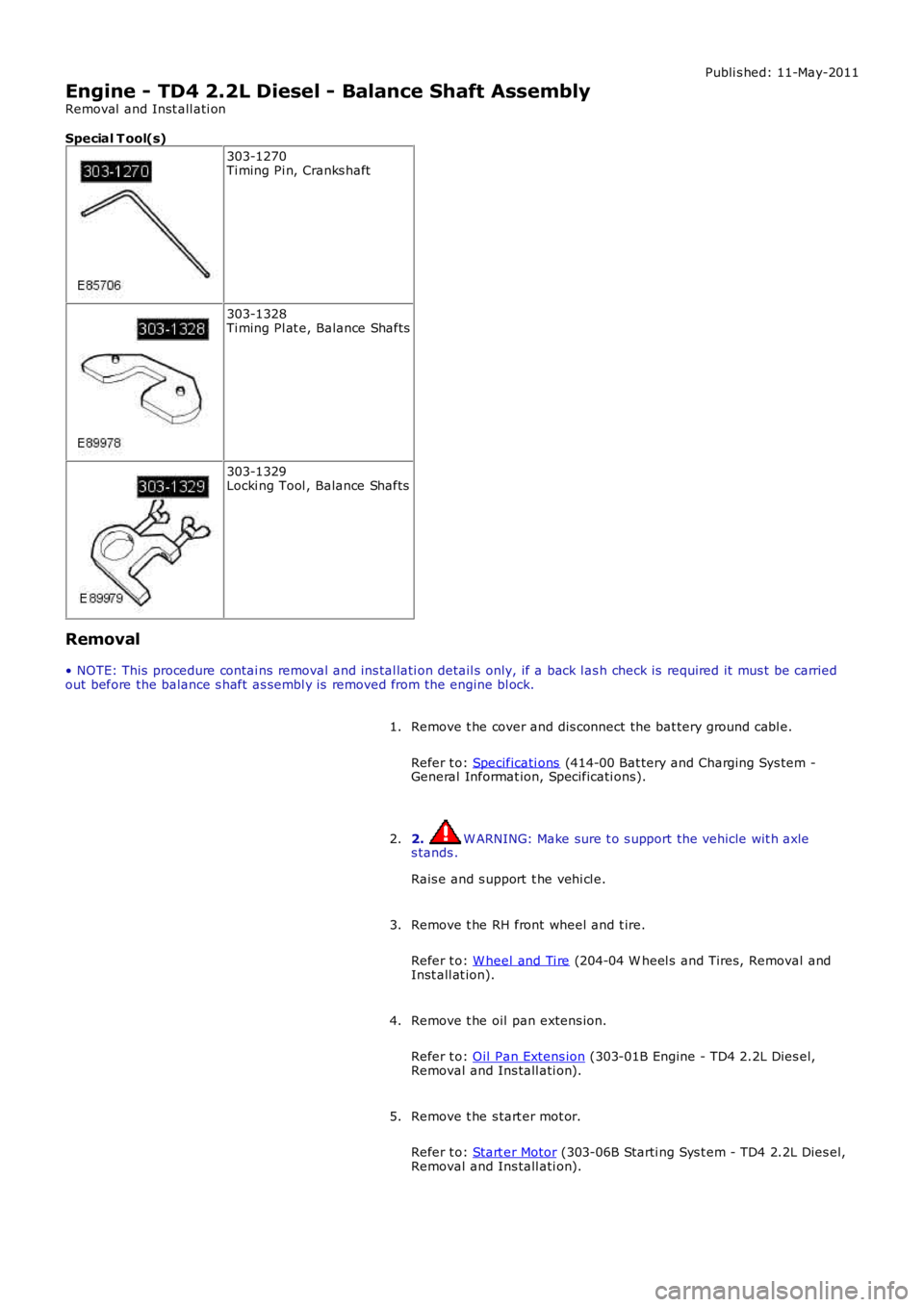
Special T ool(s)
303-1270Ti ming Pi n, Cranks haft
303-1328Ti ming Pl at e, Balance Shafts
303-1329Locki ng Tool , Balance Shafts
Removal
• NOTE: This procedure contai ns removal and ins tal lati on detail s only, if a back l ash check is required it mus t be carriedout before the balance s haft as sembl y is removed from the engine bl ock.
Remove t he cover and dis connect the bat tery ground cabl e.
Refer t o: Specificati ons (414-00 Bat tery and Charging Sys tem -General Informat ion, Specificati ons).
1.
2. W ARNING: Make sure t o s upport the vehicle wit h axles tands .
Rais e and s upport t he vehi cl e.
2.
Remove t he RH front wheel and t ire.
Refer t o: W heel and Ti re (204-04 W heel s and Tires, Removal andInst all at ion).
3.
Remove t he oil pan extens ion.
Refer t o: Oil Pan Extens ion (303-01B Engine - TD4 2.2L Dies el,Removal and Ins tall ati on).
4.
Remove t he s tart er mot or.
Refer t o: Start er Motor (303-06B Starti ng Sys t em - TD4 2.2L Dies el,Removal and Ins tall ati on).
5.
Page 892 of 3229
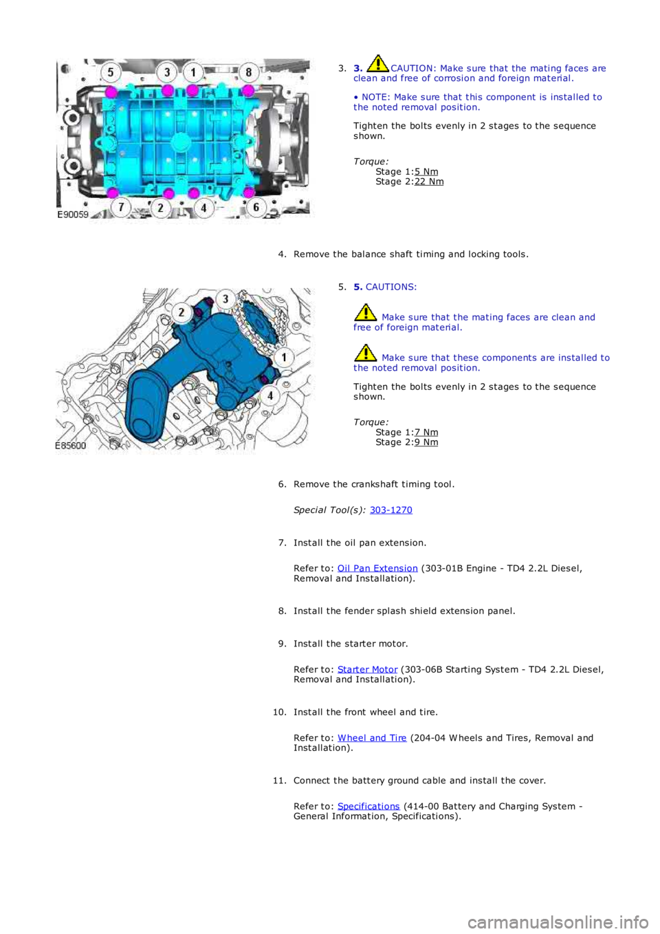
Stage 1:
Stage 2:
Stage 1:
Stage 2: 3. CAUTION: Make s ure that the mati ng faces are
clean and free of corrosi on and foreign mat eri al .
• NOTE: Make s ure that t hi s component is ins tal led t o
t he noted removal pos it ion.
Tight en the bol ts evenly i n 2 s t ages to t he s equence
s hown.
T orque: 5 Nm 22 Nm3.
Remove t he bal ance shaft ti ming and l ocking tools .
4. 5.
CAUTIONS: Make s ure that t he mat ing faces are clean and
free of foreign mat eri al. Make s ure that t hes e component s are ins tal led t o
t he noted removal pos it ion.
Tight en the bol ts evenly i n 2 s t ages to t he s equence
s hown.
T orque: 7 Nm 9 Nm5.
Remove t he cranks haft t iming t ool .
Speci al Tool (s ): 303-1270 6.
Inst all t he oil pan extens ion.
Refer t o: Oil Pan Extens ion (303-01B Engine - TD4 2.2L Dies el,
Removal and Ins tall ati on).
7.
Inst all t he fender spl as h shi el d extens ion panel.
8.
Inst all t he s tart er mot or.
Refer t o: Start er Motor (303-06B Starti ng Sys t em - TD4 2.2L Dies el,
Removal and Ins tall ati on).
9.
Inst all t he front wheel and t ire.
Refer t o: W heel and Ti re (204-04 W heel s and Tires, Removal and
Inst all at ion).
10.
Connect t he batt ery ground cable and ins tall t he cover.
Refer t o: Specificati ons (414-00 Bat tery and Charging Sys tem -
General Informat ion, Specificati ons).
11.
Page 910 of 3229
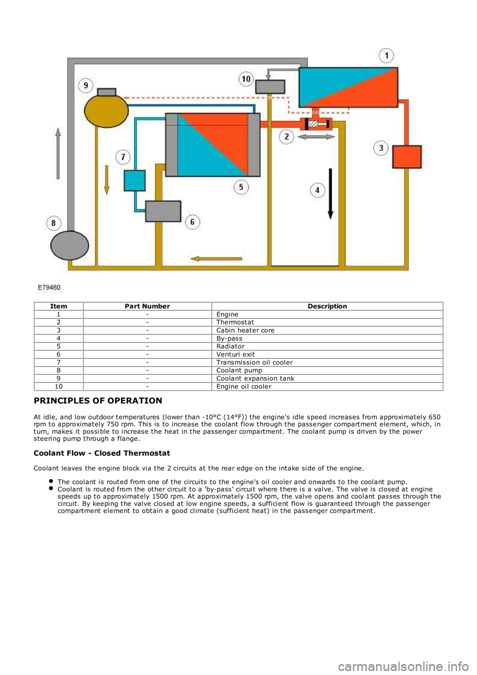
ItemPart NumberDescription
1-Engine2-Thermost at
3-Cabin heat er core
4-By-pas s5-Radiat or
6-Vent uri exi t
7-Trans mi s si on oil cool er8-Coolant pump
9-Coolant expans ion tank
10-Engine oi l cooler
PRINCIPLES OF OPERATION
At idl e, and l ow out door t emperatures (l ower t han -10°C (14°F)) the engi ne's idle s peed i ncreas es from approxi mat el y 650rpm t o approximat el y 750 rpm. Thi s is to increase the coolant flow t hrough t he pass enger compart ment element, whi ch, i nt urn, makes it pos si ble t o i ncreas e t he heat in t he pas senger compartment . The coolant pump i s dri ven by the powers teeri ng pump t hrough a flange.
Coolant Flow - Closed Thermostat
Coolant leaves the engine bl ock vi a t he 2 circui ts at t he rear edge on t he int ake side of the engi ne.
The cool ant i s rout ed from one of t he circui ts to t he engine's oi l cooler and onwards t o t he cool ant pump.Coolant is routed from the ot her ci rcuit t o a 'by-pass ' circui t where t here i s a valve. The val ve is cl osed at engines peeds up t o approximat ely 1500 rpm. At approximat el y 1500 rpm, the valve opens and cool ant pas s es through t hecircuit . By keepi ng t he val ve clos ed at low engine speeds, a suffi ci ent flow is guarant eed through the pas sengercompartment el ement to obt ain a good cl imat e (suffi ci ent heat) in t he pass enger compart ment .
Page 911 of 3229
Coolant Flow - Open Thermostat
W hen t he t hermos tat opens, coolant is al so rout ed to the radiatorThe radi at or has an inl et on the Ri ght Hand (RH) s ide and 2 out let s on t he left-hand si deThe great er volume of cooled coolant is routed at the radi ator's l ower out let t o the coolant pumpAt t he upper outl et some of the coolant is routed t o t he automat ic t rans mi ss i on's oil cool er. Before t he coolantreaches the oi l cooler, it pas ses a 'choke' circuit t hrough t he radi at or wit h a lower (s lower) fl ow t han other cool ant s .This provi des opt imum cool ing of t he cool ant before i t reaches the oi l cooler, whi ch in turn, provi des effect ivecool ing of t he transmis s ion oil . The cool ant i s rout ed from t he oil cooler onwards to t he cool ant pump.
Bleeding
The engi ne has 2 bl eed ci rcuit s connected t o t he expans ion t ank. One is l ocat ed on the radiat or and the ot her on thecyl inder head.
Radiator and Cooling Fan(s)
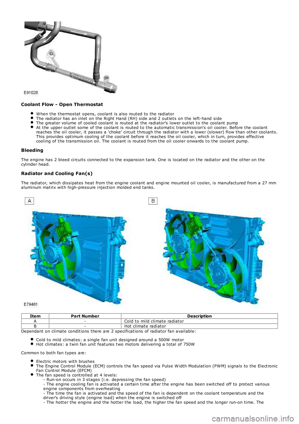
The radi at or, whi ch di s si pat es heat from t he engine cool ant and engi ne mount ed oil cooler, i s manufactured from a 27 mmalumi num mat ri x wit h hi gh-pres s ure i nject ion molded end t anks .
ItemPart NumberDescription
A-Col d t o mi ld cli mat e radiat orB-Hot cl imat e radi at or
Dependant on cli mate condit ions t here are 2 s peci fi cat ions of radiat or fan avail abl e:
Cold t o mild cl imat es : a s ingle fan unit des igned around a 500W mot orHot climat es : a t win fan unit feat ures t wo motors del iveri ng a t otal of 750W
Common t o bot h fan types are:
Electric mot ors wit h brus hesThe Engi ne Control Module (ECM) controls t he fan speed via Pul s e W i dth Modulat ion (PW M) s i gnal s to the El ect ronicFan Cont rol Module (EFCM)The fan speed i s cont rol led at 4 l evel s:- Run-on occurs i n 3 s t ages (i.e. depres s ing the fan s peed)- The engine cool ing fan i s act ivated a cert ai n t ime aft er t he engine has been s wit ched off to prot ect vari ousengi ne component s from overheati ng- The t ime the fan is act ivated and the s peed of the fan i s dependent on the coolant t emperature and thedri ver's driving s t yle (engi ne load) when t he engi ne is swi tched off- The hott er the engine and the hot ter t he load, the hi gher t he fan speed and t he longer run-on ti me. The
Page 942 of 3229
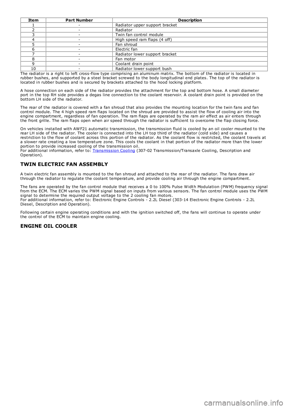
ItemPart NumberDescription
1-Radi ator upper s upport bracket
2-Radi ator3-Twin fan cont rol module
4-High s peed ram fl aps (4 off)
5-Fan shroud6-Elect ric fan
7-Radi ator lower s upport bracket
8-Fan motor9-Cool ant drain point
10-Radi ator lower s upport bus h
The radi at or is a ri ght t o l eft cros s -flow type compri si ng an alumi num mat ri x. The bot tom of the radiat or i s l ocated inrubber bus hes , and support ed by a s t eel bracket s crewed to the body l ongi tudinal end plates . The t op of the radiator i slocated i n rubber bushes and i s s ecured by bracket s at tached to the hood l ocking pl at form.
A hos e connecti on on each s ide of t he radiat or provi des the at t achment for t he t op and bot t om hos e. A s mall diamet erport i n t he top RH s ide provi des a degas l ine connect ion t o t he cool ant reservoi r. A coolant drai n point i s provided on t hebott om LH si de of the radiat or.
The rear of t he radiat or is covered wit h a fan s hroud t hat als o provides t he mounti ng locati on for t he t win fans and fancont rol module. The 4 hi gh s peed ram flaps l ocat ed on t he s hroud are provi ded to assi st t he flow of cooling ai r int o t heengi ne compart ment , regardl ess of fan operat ion. The ram fl aps are operat ed by the ram air effect as ai r ent ers throught he front gril le. The ram fl aps open when air s peed through t he radi at or is suffi ci ent t o overcome t he flap clos ing force.
On vehicles i nst all ed wit h AW F21 aut omati c transmis si on, the t rans mis s ion flui d is cooled by an oil cool er mount ed t o t herear LH s i de of the radi ator. The cooler i s connected i nto t he LH t op t hird of the radiator (col d s ide) and caus es ares t ri ct ion t o t he flow of coolant across this porti on of the radiat or. As t he cool ant flow is rest ri cted, the coolant t ravels ata s lower rate creat ing a low temperat ure zone. Thi s cool s t he cool ant i n t hat porti on of the radiator more t han the l owerport ion t o provi de increas ed cooli ng of the trans mi s si on oil .For addit ional informat ion, refer t o: Trans mis s ion Cooli ng (307-02 Trans mis s ion/Trans axle Cooli ng, Des cri pti on andOperat ion).
TWIN ELECTRIC FAN ASSEMBLY
A t win electric fan ass embl y is mount ed t o the fan s hroud and at tached to the rear of the radi ator. The fans draw airt hrough the radiator t o regul at e t he cool ant temperat ure, and provide cooli ng air t hrough the engi ne compartment .
The fans are operated by the fan cont rol module that receives a 0 to 100% Puls e W idth Modulati on (PW M) frequency s ignalfrom the ECM. The ECM varies t he PW M si gnal bas ed on inputs from vari ous sens ors . The fan cont rol module us es t he PW Ms ignal to det ermi ne the required out put vol tage t o t he 2 cooling fan mot ors .For addit ional informat ion, refer t o: Electroni c Engi ne Controls - 2.2L Dies el (303-14 El ect ronic Engine Cont rols - 2.2LDies el, Des cript ion and Operat ion).
Followi ng certai n engine operat ing condi ti ons and wit h t he ignit ion s wi tched off, the fans wil l cont inue t o operate undert he cont rol of the ECM to maint ai n engine cooling.
ENGINE OIL COOLER
Page 943 of 3229
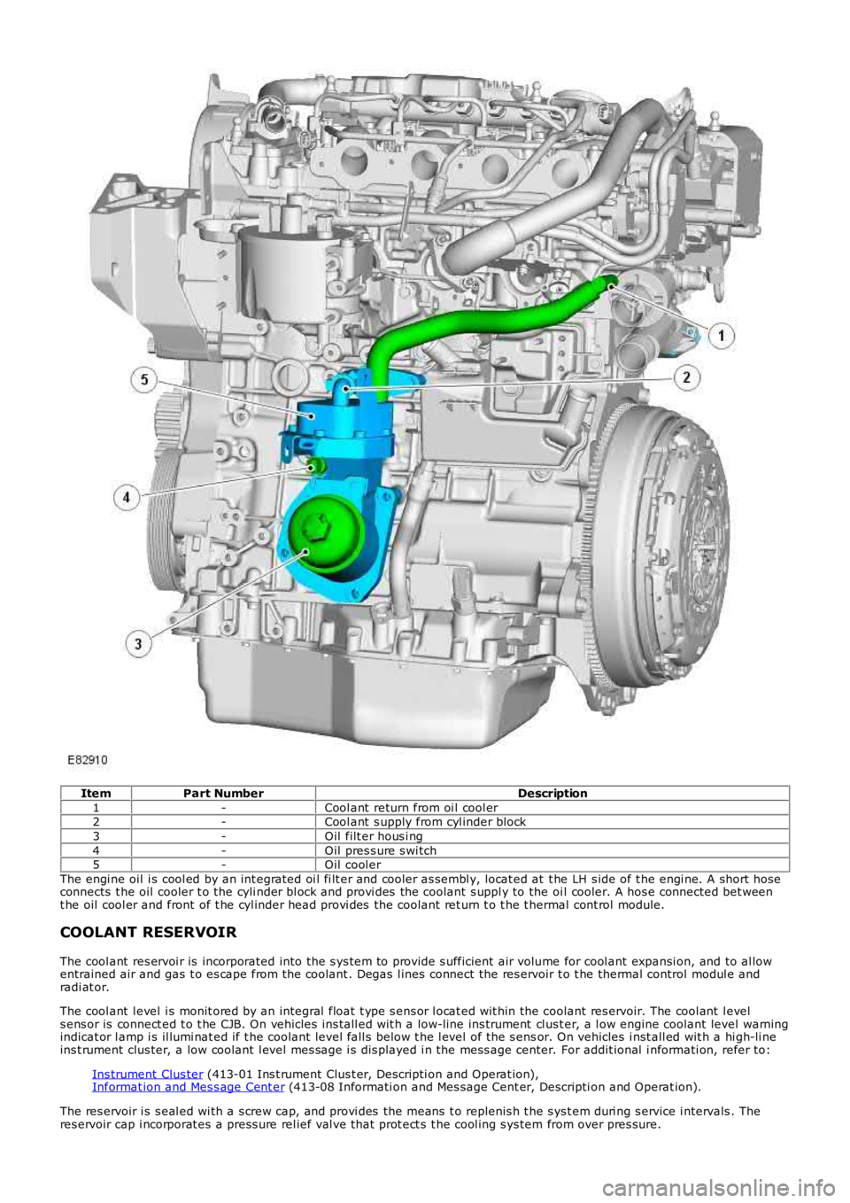
ItemPart NumberDescription
1-Cool ant return from oi l cool er2-Cool ant s upply from cyl inder block
3-Oil filt er hous i ng
4-Oil pres s ure s wi tch5-Oil cool er
The engi ne oil i s cool ed by an int egrated oi l fi lt er and cooler as sembl y, locat ed at t he LH s ide of t he engi ne. A s hort hoseconnects t he oil cooler t o the cyli nder bl ock and provi des the coolant s uppl y to the oi l cooler. A hos e connected bet weent he oil cool er and front of t he cyl inder head provi des the coolant ret urn t o t he t hermal cont rol module.
COOLANT RESERVOIR
The cool ant res ervoi r is incorporated into the s ys tem to provide s ufficient air volume for cool ant expansi on, and to al lowentrained air and gas t o es cape from the coolant . Degas l ines connect the res ervoir t o t he thermal control modul e andradi at or.
The cool ant l evel i s monit ored by an integral float t ype s ens or l ocat ed wit hin the coolant res ervoir. The cool ant l evels ens or is connect ed t o t he CJB. On vehicles ins tall ed wit h a low-line ins trument cl us t er, a l ow engine coolant level warningindicat or l amp i s il lumi nat ed if t he coolant level fall s below t he l evel of the s ensor. On vehicles i nst all ed wit h a hi gh-li neins t rument clus ter, a low coolant l evel mes sage i s dis played i n the mess age center. For addit ional i nformati on, refer to:
Ins trument Clus ter (413-01 Ins t rument Clus t er, Descripti on and Operat ion),Informat ion and Mes s age Cent er (413-08 Informati on and Mes sage Cent er, Descripti on and Operat ion).
The res ervoir i s s eal ed wi th a s crew cap, and provi des the means t o replenis h t he s ys t em duri ng s ervice i ntervals . Theres ervoir cap i ncorporat es a press ure rel ief val ve that prot ect s t he cool ing s ys tem from over pres sure.
Page 946 of 3229
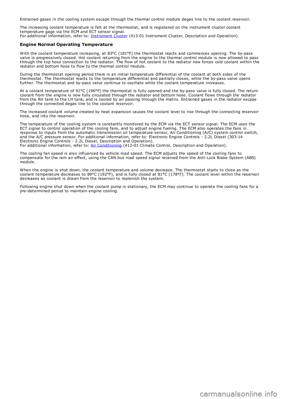
Entrained gases i n t he cool ing s ys tem escape t hrough the t hermal control modul e degas l ine t o t he cool ant res ervoir.
The increas ing coolant temperature is felt at t he t hermos tat , and is regi s tered on the ins trument cl us t er coolantt emperature gage vi a t he ECM and ECT s ens or s i gnal.For addit ional informat ion, refer t o: Ins t rument Clus ter (413-01 Inst rument Cl us t er, Des cript ion and Operat ion).
Engine Normal Operating Temperature
W i th the coolant t emperature increas ing, at 83°C (181°F) t he t hermos tat reacts and commences openi ng. The by-pas svalve is progres s ively clos ed. Hot coolant ret urning from t he engi ne t o t he thermal control modul e i s now all owed to pas st hrough the t op hos e connecti on to the radiator. The fl ow of hot coolant t o t he radiat or now forces cold cool ant wi thi n t heradi at or and bot t om hos e t o fl ow t o t he thermal cont rol module.
Duri ng the thermos t at opening period t here i s an i nit ial temperat ure di fferenti al of t he coolant at bot h s ides of t het hermos tat . The thermos t at react s t o t he t emperature different ial and part iall y closes , whi le t he by-pas s val ve opensfurther. The thermos t at and by-pas s valve conti nue to oscil lat e whil e t he cool ant t emperat ure i ncreas es .
At a coolant temperat ure of 91°C (196°F) t he thermost at is full y opened and t he by-pas s valve i s ful ly clos ed. The returncool ant from t he engi ne is now ful ly circul ated t hrough t he radiat or and bot tom hose. Coolant flows t hrough the radiat orfrom the RH tank t o t he LH t ank, and i s cool ed by air pass i ng through the mat ri x. Ent rai ned gas es i n the radiat or es capet hrough the connect ed degas l ine t o t he cool ant res ervoir.
The increas ed cool ant volume created by heat expans ion caus es the coolant level to ri se through t he connecti ng res ervoirhose, and i nt o t he res ervoi r.
The t emperature of the cooli ng s ys t em i s cons t ant ly moni tored by t he ECM via the ECT s ens or s i gnal. The ECM uses t heECT s ignal to control operati on of the cooling fans , and to adjus t engine fueling. The ECM al so operates t he fans i nres ponse to input s from the aut omati c t ransmis s ion oil t emperat ure s ensor, Air Condit ioning (A/C) s ys tem cont rol s wit ch,and t he A/C pres sure s ens or. For addit ional i nformati on, refer to: El ect ronic Engine Cont rols - 2.2L Di es el (303-14Electroni c Engine Controls - 2.2L Dies el, Des cript ion and Operat ion).For addit ional informat ion, refer t o: Air Condit ioning (412-01 Cli mat e Cont rol , Descripti on and Operat ion).
The cool ing fan s peed is als o infl uenced by vehicle road s peed. The ECM adjus t s the speed of t he cool ing fans tocompens ate for t he ram air effect , us ing t he CAN bus road speed s ignal received from the Ant i-Lock Brake Sys tem (ABS)module.
W hen t he engine i s s hut down, t he coolant t emperature and volume decreas e. The thermos t at st art s t o clos e as t hecool ant t emperat ure decreas es to 89°C (192°F), and is fully cl osed at 81°C (178°F). The coolant level wit hin t he res ervoi rdecreas es as coolant is drawn from the res ervoi r to replenis h the s ys tem.
Followi ng engi ne s hut down when the coolant pump i s s tat ionary, the ECM may cont inue t o operat e t he cool ing fans for apre-det ermined peri od to maint ai n engine cooling.
Page 981 of 3229
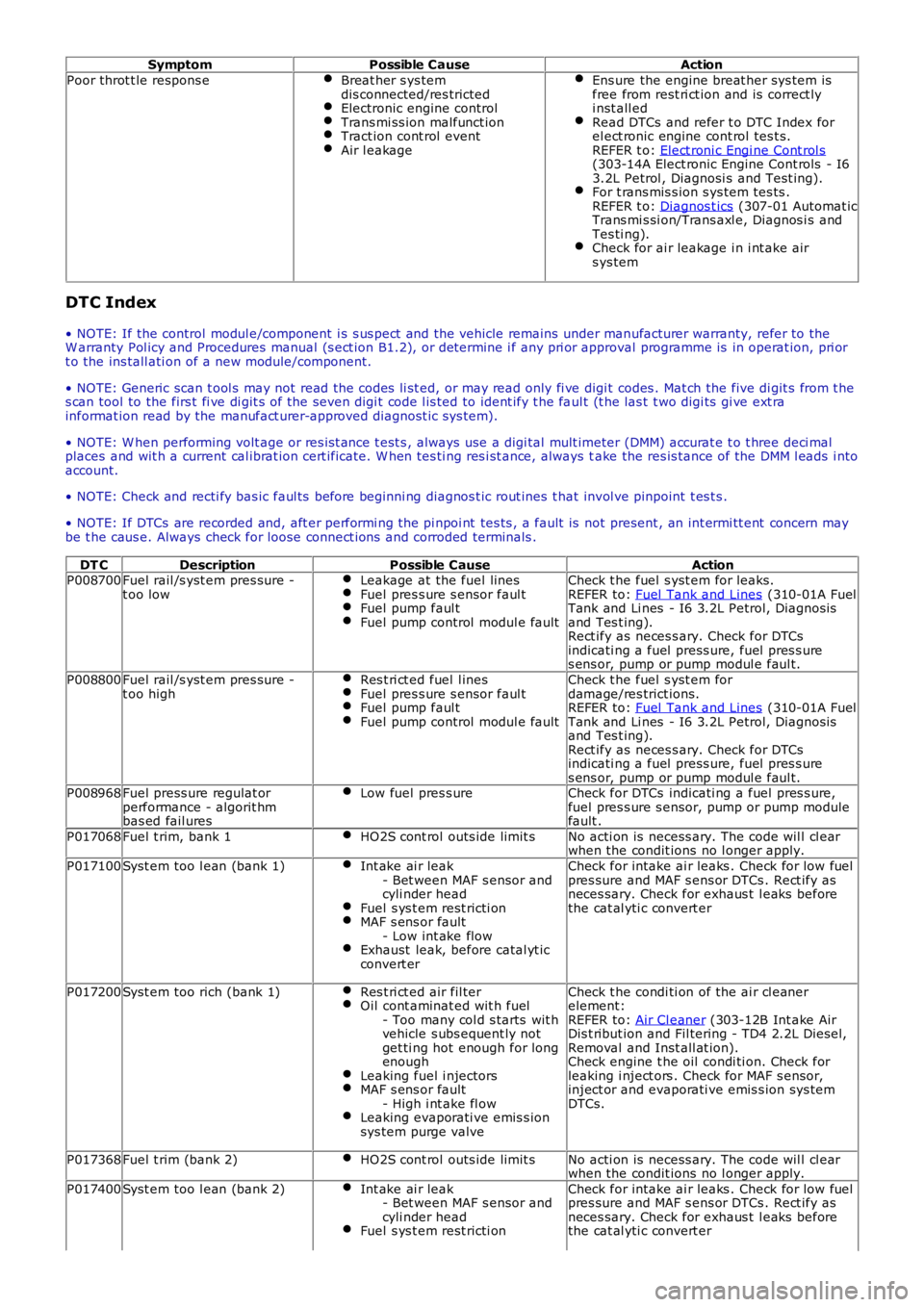
SymptomPossible CauseAction
Poor throt t le respons eBreat her s ys temdis connected/res trictedElectronic engine controlTrans mi ss ion malfunct ionTract ion cont rol eventAir l eakage
Ens ure the engine breat her sys tem isfree from rest ri ct ion and is correct lyi nst all edRead DTCs and refer t o DTC Index forel ect ronic engine cont rol tes t s.REFER t o: Elect roni c Engi ne Cont rol s(303-14A Elect ronic Engine Cont rols - I63.2L Petrol , Diagnosi s and Test ing).For t rans mis s ion s ys tem tes ts .REFER t o: Diagnos t ics (307-01 Automat icTrans mi s si on/Trans axl e, Diagnos i s andTes ti ng).Check for ai r leakage i n i nt ake airs ys tem
DTC Index
• NOTE: If the control modul e/component i s s us pect and the vehicle remains under manufacturer warranty, refer to theW arranty Pol icy and Procedures manual (s ect ion B1.2), or determine i f any pri or approval programme is in operat ion, pri ort o the ins tall ati on of a new module/component.
• NOTE: Generic scan t ool s may not read the codes li st ed, or may read only fi ve digit codes . Mat ch the five di git s from t hes can tool to the firs t fi ve di git s of the seven digi t code l is ted to ident ify t he faul t (t he las t t wo digi ts gi ve ext rainformat ion read by the manufact urer-approved diagnost ic s ys tem).
• NOTE: W hen performing volt age or res is t ance t est s , always use a digi tal mult imeter (DMM) accurat e t o t hree deci malplaces and wit h a current cal ibrat ion cert ificate. W hen tes ti ng res i st ance, always take the res is tance of the DMM l eads i ntoaccount.
• NOTE: Check and recti fy bas ic faul ts before beginni ng diagnos t ic rout ines t hat invol ve pinpoint t es t s .
• NOTE: If DTCs are recorded and, aft er performi ng the pi npoi nt tes ts , a fault is not present , an int ermi tt ent concern maybe t he caus e. Always check for loose connect ions and corroded terminals .
DT CDescriptionPossible CauseActionP008700Fuel rail /s yst em pres sure -t oo lowLeakage at the fuel linesFuel pres s ure s ensor faul tFuel pump faul tFuel pump control modul e fault
Check t he fuel s yst em for leaks.REFER to: Fuel Tank and Lines (310-01A FuelTank and Li nes - I6 3.2L Petrol, Diagnos isand Tes t ing).Rect ify as neces s ary. Check for DTCsindicati ng a fuel press ure, fuel pres s ures ens or, pump or pump modul e faul t.
P008800Fuel rail /s yst em pres sure -t oo highRes t ri ct ed fuel l inesFuel pres s ure s ensor faul tFuel pump faul tFuel pump control modul e fault
Check t he fuel s yst em fordamage/res trict ions.REFER to: Fuel Tank and Lines (310-01A FuelTank and Li nes - I6 3.2L Petrol, Diagnos isand Tes t ing).Rect ify as neces s ary. Check for DTCsindicati ng a fuel press ure, fuel pres s ures ens or, pump or pump modul e faul t.P008968Fuel press ure regulat orperformance - algorit hmbas ed fail ures
Low fuel pres s ureCheck for DTCs indicati ng a fuel pres s ure,fuel pres s ure s ensor, pump or pump modulefault .
P017068Fuel t rim, bank 1HO2S cont rol outs ide limit sNo acti on is necess ary. The code wil l cl earwhen the condit ions no l onger apply.
P017100Syst em too l ean (bank 1)Int ake ai r leak- Bet ween MAF s ensor andcyli nder headFuel s ys t em rest ricti onMAF s ens or fault- Low int ake flowExhaust leak, before catal yt icconvert er
Check for intake ai r leaks . Check for low fuelpres sure and MAF s ens or DTCs . Rect ify asneces sary. Check for exhaus t l eaks beforethe cat al yti c convert er
P017200Syst em too rich (bank 1)Res t ri ct ed air fil terOil cont aminat ed wit h fuel- Too many col d s tarts wit hvehicle s ubs equent ly notget ti ng hot enough for longenoughLeaking fuel i njectorsMAF s ens or fault- High i nt ake fl owLeaking evaporati ve emis s ionsys tem purge valve
Check t he condi ti on of the ai r cl eanerelement:REFER to: Air Cl eaner (303-12B Int ake AirDis t ribut ion and Fil tering - TD4 2.2L Dies el,Removal and Inst all at ion).Check engine t he oil condi ti on. Check forleaking i nject ors . Check for MAF s ensor,inject or and evaporati ve emis s ion sys temDTCs.
P017368Fuel t rim (bank 2)HO2S cont rol outs ide limit sNo acti on is necess ary. The code wil l cl earwhen the condit ions no l onger apply.
P017400Syst em too l ean (bank 2)Int ake ai r leak- Bet ween MAF s ensor andcyli nder headFuel s ys t em rest ricti on
Check for intake ai r leaks . Check for low fuelpres sure and MAF s ens or DTCs . Rect ify asneces sary. Check for exhaus t l eaks beforethe cat al yti c convert er