2006 LAND ROVER FRELANDER 2 engine oil
[x] Cancel search: engine oilPage 982 of 3229
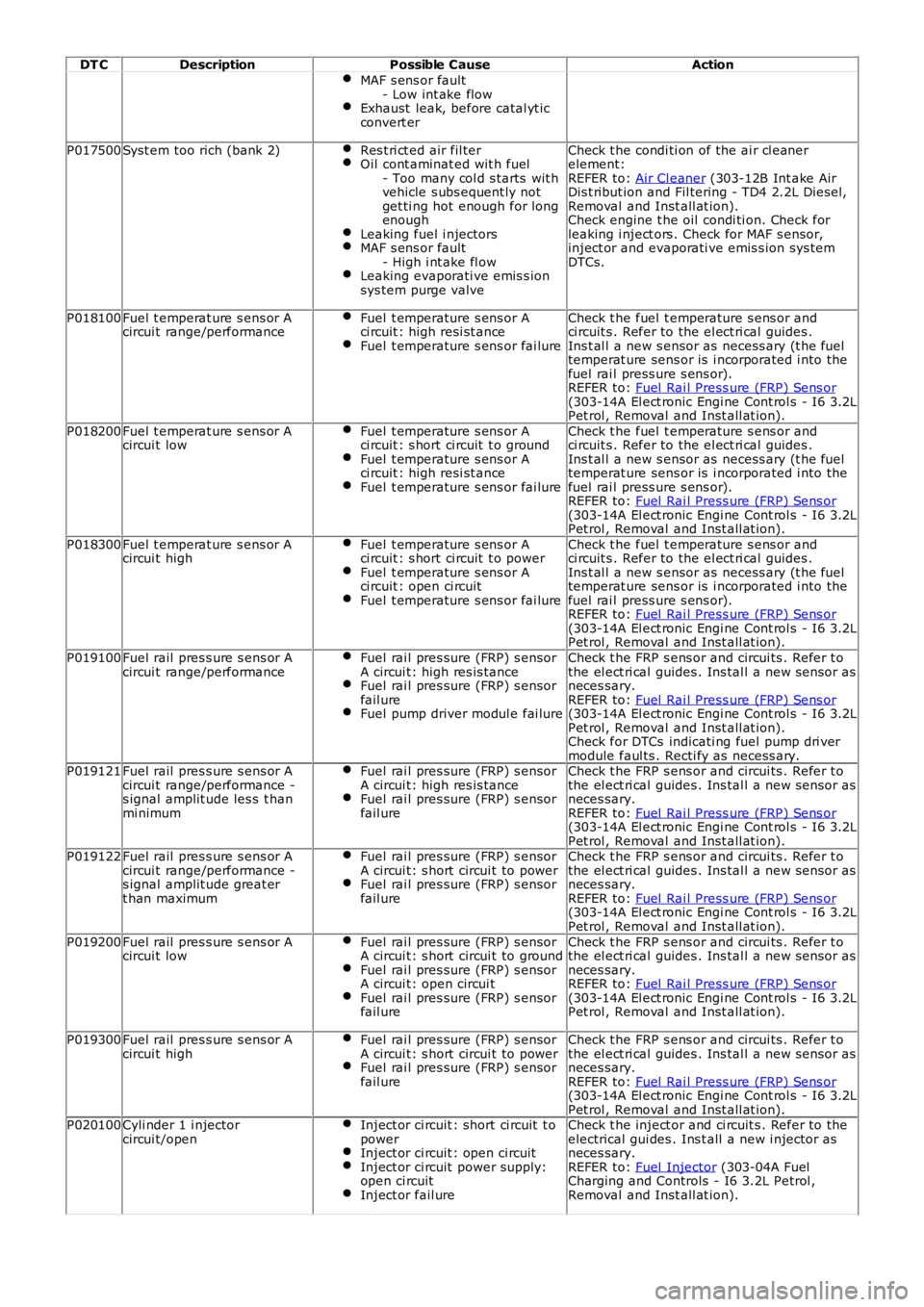
DT CDescriptionPossible CauseAction
MAF s ens or fault- Low int ake flowExhaust leak, before catal yt icconvert er
P017500Syst em too rich (bank 2)Res t ri ct ed air fil terOil cont aminat ed wit h fuel- Too many col d s tarts wit hvehicle s ubs equent ly notget ti ng hot enough for longenoughLeaking fuel i njectorsMAF s ens or fault- High i nt ake fl owLeaking evaporati ve emis s ionsys tem purge valve
Check t he condi ti on of the ai r cl eanerelement:REFER to: Air Cl eaner (303-12B Int ake AirDis t ribut ion and Fil tering - TD4 2.2L Dies el,Removal and Inst all at ion).Check engine t he oil condi ti on. Check forleaking i nject ors . Check for MAF s ensor,inject or and evaporati ve emis s ion sys temDTCs.
P018100Fuel t emperat ure s ens or Acircui t range/performanceFuel t emperature s ens or Aci rcuit : high resi st anceFuel t emperature s ens or fai lure
Check t he fuel t emperature s ens or andci rcuit s . Refer to the el ect ri cal guides .Ins t al l a new s ensor as necess ary (t he fueltemperat ure sens or is i ncorporated i nto thefuel rai l press ure s ens or).REFER to: Fuel Rai l Press ure (FRP) Sens or(303-14A El ect ronic Engi ne Cont rol s - I6 3.2LPet rol , Removal and Inst all at ion).
P018200Fuel t emperat ure s ens or Acircui t lowFuel t emperature s ens or Aci rcuit : s hort ci rcuit t o groundFuel t emperature s ens or Aci rcuit : high resi st anceFuel t emperature s ens or fai lure
Check t he fuel t emperature s ens or andci rcuit s . Refer to the el ect ri cal guides .Ins t al l a new s ensor as necess ary (t he fueltemperat ure sens or is i ncorporated i nto thefuel rai l press ure s ens or).REFER to: Fuel Rai l Press ure (FRP) Sens or(303-14A El ect ronic Engi ne Cont rol s - I6 3.2LPet rol , Removal and Inst all at ion).
P018300Fuel t emperat ure s ens or Acircui t highFuel t emperature s ens or Aci rcuit : s hort ci rcuit t o powerFuel t emperature s ens or Aci rcuit : open ci rcuitFuel t emperature s ens or fai lure
Check t he fuel t emperature s ens or andci rcuit s . Refer to the el ect ri cal guides .Ins t al l a new s ensor as necess ary (t he fueltemperat ure sens or is i ncorporated i nto thefuel rai l press ure s ens or).REFER to: Fuel Rai l Press ure (FRP) Sens or(303-14A El ect ronic Engi ne Cont rol s - I6 3.2LPet rol , Removal and Inst all at ion).
P019100Fuel rail pres s ure s ens or Acircui t range/performanceFuel rai l pres sure (FRP) s ensorA circui t: high res is tanceFuel rai l pres sure (FRP) s ensorfail ureFuel pump driver modul e fai lure
Check t he FRP s ens or and circui ts . Refer t othe el ect ri cal guides . Ins tal l a new s ensor asneces sary.REFER to: Fuel Rai l Press ure (FRP) Sens or(303-14A El ect ronic Engi ne Cont rol s - I6 3.2LPet rol , Removal and Inst all at ion).Check for DTCs indicati ng fuel pump dri vermodule faul ts . Recti fy as necess ary.P019121Fuel rail pres s ure s ens or Acircui t range/performance -s ignal amplit ude les s t hanmi nimum
Fuel rai l pres sure (FRP) s ensorA circui t: high res is tanceFuel rai l pres sure (FRP) s ensorfail ure
Check t he FRP s ens or and circui ts . Refer t othe el ect ri cal guides . Ins tal l a new s ensor asneces sary.REFER to: Fuel Rai l Press ure (FRP) Sens or(303-14A El ect ronic Engi ne Cont rol s - I6 3.2LPet rol , Removal and Inst all at ion).P019122Fuel rail pres s ure s ens or Acircui t range/performance -s ignal amplit ude great ert han maximum
Fuel rai l pres sure (FRP) s ensorA circui t: s hort circui t to powerFuel rai l pres sure (FRP) s ensorfail ure
Check t he FRP s ens or and circui ts . Refer t othe el ect ri cal guides . Ins tal l a new s ensor asneces sary.REFER to: Fuel Rai l Press ure (FRP) Sens or(303-14A El ect ronic Engi ne Cont rol s - I6 3.2LPet rol , Removal and Inst all at ion).
P019200Fuel rail pres s ure s ens or Acircui t lowFuel rai l pres sure (FRP) s ensorA circui t: s hort circui t to groundFuel rai l pres sure (FRP) s ensorA circui t: open circui tFuel rai l pres sure (FRP) s ensorfail ure
Check t he FRP s ens or and circui ts . Refer t othe el ect ri cal guides . Ins tal l a new s ensor asneces sary.REFER to: Fuel Rai l Press ure (FRP) Sens or(303-14A El ect ronic Engi ne Cont rol s - I6 3.2LPet rol , Removal and Inst all at ion).
P019300Fuel rail pres s ure s ens or Acircui t highFuel rai l pres sure (FRP) s ensorA circui t: s hort circui t to powerFuel rai l pres sure (FRP) s ensorfail ure
Check t he FRP s ens or and circui ts . Refer t othe el ect ri cal guides . Ins tal l a new s ensor asneces sary.REFER to: Fuel Rai l Press ure (FRP) Sens or(303-14A El ect ronic Engi ne Cont rol s - I6 3.2LPet rol , Removal and Inst all at ion).P020100Cyli nder 1 i njectorcircui t/openInject or ci rcuit : short ci rcuit t opowerInject or ci rcuit : open ci rcuitInject or ci rcuit power supply:open ci rcuitInject or fail ure
Check t he inject or and ci rcuit s . Refer to theelectrical gui des . Ins t all a new i njector asneces sary.REFER to: Fuel Injector (303-04A FuelCharging and Controls - I6 3.2L Petrol ,Removal and Inst all at ion).
Page 997 of 3229
(23,206 psi ).
The fuel s yst em HP pump compri ses t he fol lowi ng components :
3 HP pumpi ng element sInt egral li ft pumpVolume Cont rol Valve (VCV).
The HP pump and integral l ift pump mus t not be s eparat ed. The HP pump i s not ti med to t he engi ne.
A controlled amount of fuel i s all owed to leak-off t hrough t he HP pump, and ret urned t hrough a l eak-off pipe t o t he fuelfi lt er. The l eak-off fuel provides cooling and lubri cat ion for the HP pump int ernal components .
Lift Pump
A fuel l ift pump i s mounted t o t he rear of t he fuel pump, and forms an int egral ass embly wit h t he HP pump. The fuel li ftpump i s a gear type pump and connect ed to the fuel fi lt er s upply l ine. The li ft pump creat es a vacuum (negati ve pres s ure)in the s upply l ine t o t he fuel t ank, and draws the fuel from t he tank. The fuel passes t hrough the fuel fi lt er and i s t hendelivered at lift pump pres s ure to the HP pump inl et port.
The li ft pump normal operati ng, negati ve pres sure values are shown for the foll owing engine condi ti ons:
Engine ConditionLift Pump Negative PressureCranking-133 ± 7 mbar (-10 ± 0.5 cmHg)
Full load-267 ± 133 mbar (-20 ± 10 cmHg)
Volume Control Valve (VCV)
The VCV i s mounted on the HP pump, and l ocat ed in the feed port between t he HP pump elements and the fuel l ift pump.The VCV i s a vari abl e pos it ion s olenoid-operat ed valve t hat i s cont rol led by t he ECM wit h a 12V Puls e W idt h Modulat ed(PW M) s ignal. The VCV controls t he quant it y of fuel deli vered by the lift pump t o t he HP pump el ements .
W hen t he HP fuel pump rot ates , pres sure is created when t he VCV i s open and the fuel rail mount ed PCV is cl osed. TheVCV and PCV are vari abl e posi ti on valves, and us ed by t he ECM t o cont rol fuel deli very and fuel s ys tem pres sure.
Duri ng the fuel heat ing period when t he s uppl y fuel t emperature is les s than 40°C (104°F), t he ECM will fully open theVCV. Fuel volume and press ure is t hen cont rol led di rectl y by the PCV under t he cont rol of the ECM.
The VCV i s normal ly open when t he s ol enoi d i s not energi zed by the ECM. The resi s tance val ue of the VCV s ol enoi d coil is2.8 ohms at 20°C (68°F).For addit ional informat ion, refer t o: Electroni c Engi ne Controls - 2.2L Dies el (303-14 El ect ronic Engine Cont rols - 2.2LDies el, Des cript ion and Operat ion).
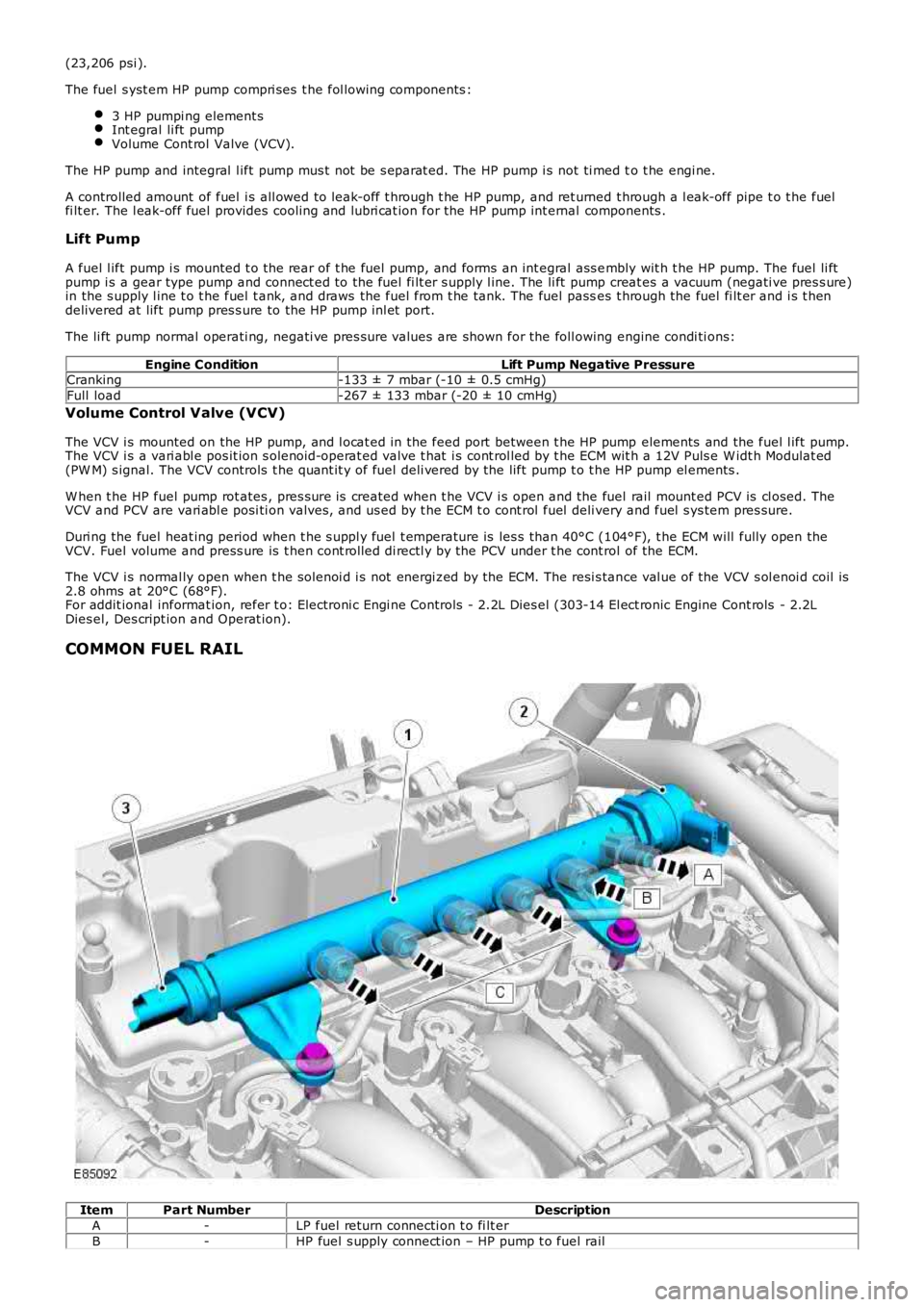
COMMON FUEL RAIL
ItemPart NumberDescription
A-LP fuel return connecti on t o fi lt er
B-HP fuel s upply connect ion – HP pump t o fuel rail
Page 1024 of 3229
Publi s hed: 11-May-2011
Fuel Charging and Controls - Turbocharger - TD4 2.2L Diesel -
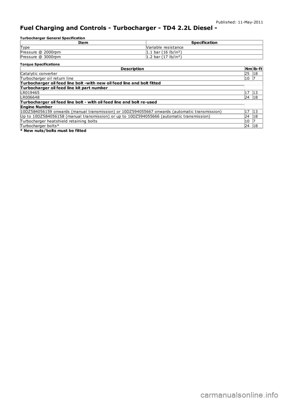
Turbocharger General SpecificationItemSpecification
TypeVariable res is t ance
Pres s ure @ 2000rpm1.1 bar (16 lb/in²)Pres s ure @ 3000rpm1.2 bar (17 lb/in²)
Torque SpecificationsDescriptionNmlb-ft
Catal yt ic convert er2518
Turbocharger oi l ret urn l ine107T urbocharger oil feed line bolt -w ith new oil feed line and bolt fitted
T urbocharger oil feed line kit part number
LR0194651713LR0066482418
T urbocharger oil feed line bolt - with oil feed line and bolt re-used
Engine Number10DZ584056159 onwards (manual t ransmis s ion) or 10DZ594055667 onwards (automat ic t rans mis s ion)1713
Up t o 10DZ584056158 (manual t rans mis s ion) or up to 10DZ594055666 (automat ic t rans miss ion)2418
Turbocharger heat shi el d ret aini ng bol ts107Turbocharger bol ts *2418
* New nuts/bolts must be fitted
Page 1025 of 3229
Publi s hed: 11-May-2011
Fuel Charging and Controls - Turbocharger - TD4 2.2L Diesel - Turbocharger
Des cript ion and Operat ion
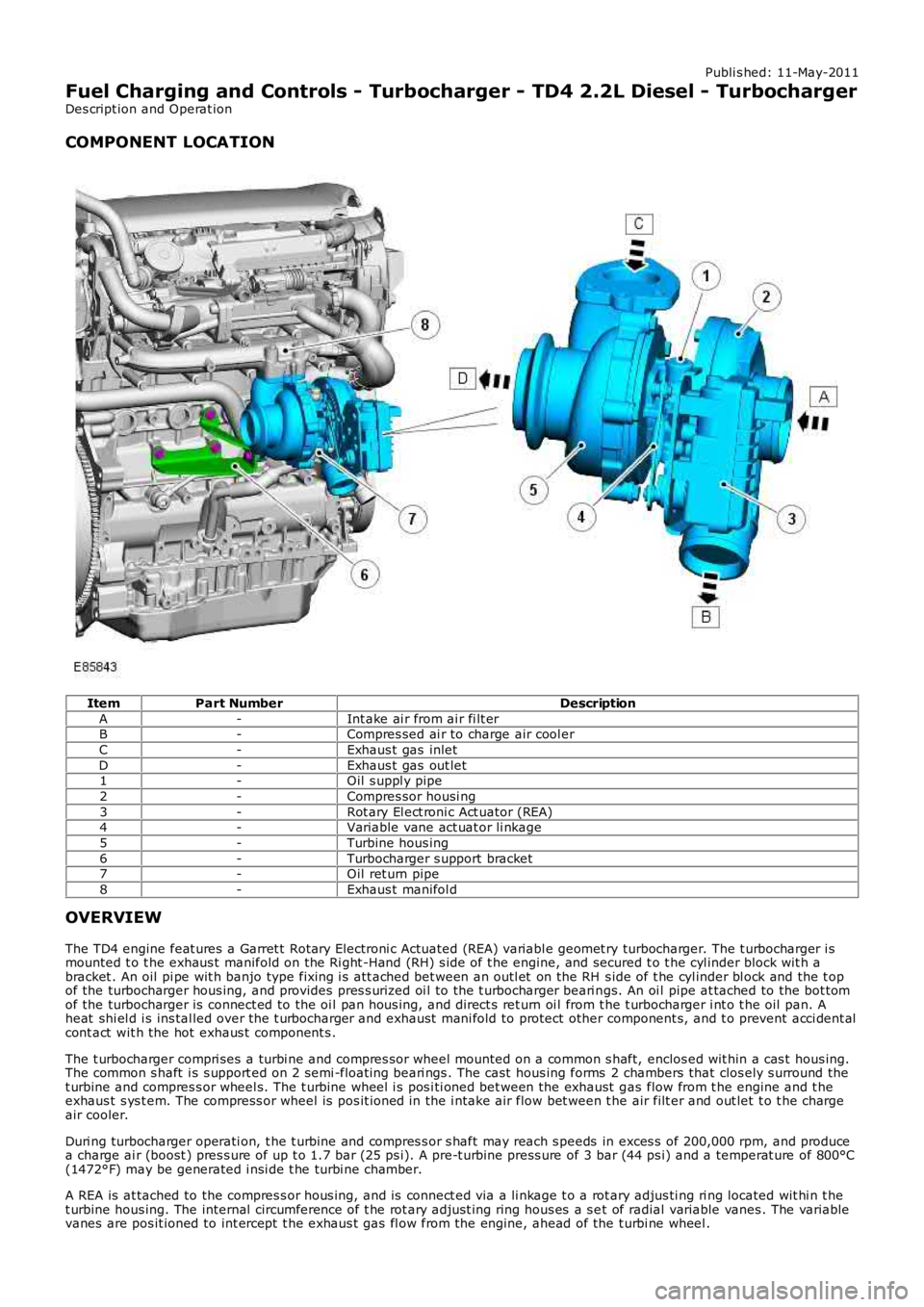
COMPONENT LOCATION
ItemPart NumberDescription
A-Int ake ai r from ai r fi lt erB-Compres sed ai r to charge air cool er
C-Exhaus t gas inlet
D-Exhaus t gas out let1-Oil s uppl y pipe
2-Compres sor housi ng
3-Rot ary El ect roni c Act uator (REA)4-Variable vane act uat or li nkage
5-Turbine hous ing
6-Turbocharger s upport bracket7-Oil ret urn pipe
8-Exhaus t manifol d
OVERVIEW
The TD4 engine feat ures a Garret t Rotary Electroni c Actuated (REA) variabl e geomet ry turbocharger. The t urbocharger i smounted t o t he exhaus t manifold on the Ri ght -Hand (RH) s ide of t he engine, and secured t o t he cyl inder block wit h abracket . An oil pi pe wit h banjo type fixing i s att ached bet ween an outl et on the RH s ide of t he cyl inder bl ock and the t opof the turbocharger hous ing, and provides pres s uri zed oi l to the t urbocharger beari ngs. An oi l pipe at tached to the bot tomof the turbocharger is connect ed to the oi l pan hous ing, and direct s ret urn oi l from t he t urbocharger i nt o t he oil pan. Aheat shi el d i s ins tal led over the t urbocharger and exhaust mani fold to protect other component s, and t o prevent acci dent alcont act wit h the hot exhaus t component s .
The t urbocharger compri ses a turbi ne and compres sor wheel mounted on a common s haft, enclos ed wit hin a cas t hous ing.The common s haft i s s upport ed on 2 semi -float ing beari ngs . The cast hous ing forms 2 chambers that clos ely s urround thet urbine and compres s or wheel s. The t urbine wheel i s pos i ti oned bet ween the exhaust gas flow from t he engine and t heexhaus t s ys t em. The compress or wheel is pos it ioned in the i ntake air flow bet ween t he air filt er and out let t o t he chargeair cooler.
Duri ng turbocharger operati on, t he t urbine and compres s or s haft may reach s peeds in exces s of 200,000 rpm, and producea charge ai r (boost ) pres s ure of up t o 1.7 bar (25 ps i). A pre-t urbine press ure of 3 bar (44 ps i) and a temperat ure of 800°C(1472°F) may be generated i nsi de t he turbi ne chamber.
A REA is at tached to the compres s or hous ing, and is connect ed via a li nkage t o a rotary adjus ti ng ri ng located wit hi n t het urbine hous ing. The internal circumference of t he rot ary adjus t ing ring hous es a s et of radial variable vanes . The variablevanes are pos it ioned to int ercept t he exhaus t gas fl ow from the engine, ahead of the t urbi ne wheel .
Page 1027 of 3229
At low engi ne s peed t he volume of exhaust gas l eavi ng the engine is l ow. The vanes are moved toward the cl osed pos it iont o direct t he exhaus t gas fl ow t o t he out s ide edge of t he turbine wheel. The clos ed posi ti on of the vanes creates ares t ri ct ion t o t he gas fl ow and i ncreas es t he gas vel oci ty to the t urbine wheel . The turbi ne wheel s peed is increas ed,cons equent ly producing more charge ai r (boos t pres sure) from t he compres sor.
B - Moderate Engine Speed
As engine s peed and exhaus t gas vol ume increas e, the vanes are moved to the open posit ion t o direct t he exhaus t gasfl ow t oward t he center of the turbi ne wheel . The vanes do not rest ri ct the exhaus t gas flow and therefore exhaus t gasveloci ty is dependant on engine s peed. The t urbi ne wheel s peed is maintai ned due to the i ncreas ed velocit y of t he gas esleaving t he engine and being di rected t oward the center area of t he t urbine wheel .
C - Maximum Engine Speed
At maximum engine s peed the volume of exhaus t gas leavi ng t he engi ne is hi gh. The vanes are moved toward the full yopen pos i ti on and do not affect t he gas vel oci ty. The exhaus t gas fl ow contacts t he center area of t he t urbine wheel tomaint ain t he t urbine wheel s peed and boos t pres s ure from the compress or.
Over-Boost Pressure
Duri ng periods of medi um t o hard accelerat ion, the turbocharger is requi red t o produce a l imit ed period of over-boos tpres s ure from the compress or to meet the current engi ne fueli ng requirement. The ECM wil l reques t and all ow t he REA t omove t he variable vanes t oward t he clos ed posi ti on t o increas e t he vel oci ty of t he already high-s peed turbine wheel. Theover-boos t condit ion is all owed by t he ECM for t he l imi ted period.
Barometric Pressure Sensor
At high al ti tude t he t urbocharger wi ll functi on normal ly, but due t o t he l ower ambi ent ai r pres sure t he turbi ne andcompres sor may tend t o over-speed. A baromet ri c pres sure s ensor i s located i n t he ECM t o prevent over-boost andposs i bl e engine damage occurri ng under t hes e condit ions. The ECM opens t he vari abl e vanes earlier duri ng t he openi ngphas e to s uit the al ti tude of t he vehi cl e.
T urbocharger Lubrication
The rapi d accelerat ion and decelerat ion demands of t he turbocharger rel y on a s t eady flow of cl ean oil. The oi l suppli ed byt he engi ne lubri cat ion s ys tem provides l ubricati on to the t urbocharger shaft and bearings, whi le al so act ing as a cool antfor t he t urbocharger cent er hous i ng.
To mai nt ain the l ife expect ancy of t he turbocharger, t he engine oil mus t be replenished at regular s ervice i nt ervals wit ht he recommended qual it y and quant it y of oil . The oi l mus t have a free-fl ow t hrough the turbocharger and an unres trict edret urn to t he engine oi l pan.
Page 1077 of 3229
Publi s hed: 11-May-2011
Starting System - I6 3.2L Petrol - Starting System
Diagnosi s and Tes ti ng
Principles of Operation
For a detail ed descripti on of the st art ing s ys tem, refer t o the relevant Descri pti on and Operat ion s ect ion in t he works hopmanual.REFER to: St art ing Syst em (303-06A St art ing Sys tem - I6 3.2L Petrol, Des cript ion and Operat ion) /Starti ng Sys t em (303-06B St arti ng Syst em - TD4 2.2L Di es el, Des cri pt ion and Operati on).
Inspection and Verification
CAUTION: Di agnos is by s ubs ti tut ion from a donor vehicle is NO T acceptabl e. Subs ti tut ion of cont rol modules doesnot guarant ee confirmat ion of a faul t, and may als o caus e addit ional fault s i n t he vehi cl e being t est ed and/or t he donorvehi cl e.
1. Verify t he cus t omer concern.1.
2. Vis ually ins pect for obvious s igns of mechani cal or electrical damage.2.
Visual Inspection
MechanicalElectrical
Gear s el ect or lever cable adjust mentSt arter Mot orBatt ery
Bat teryFus esW iring harnes sDamaged, loos e or corroded connectorsSt art er relayEngine Cont rol Module (ECM)
3. If an obvious cause for an obs erved or report ed concern is found, correct t he caus e (if pos s ible) beforeproceeding t o t he next s t ep3.
4. If t he caus e is not vis ually evi dent , verify t he sympt om and refer t o t he Sympt om Chart, al ternat ively, check forDi agnos ti c Trouble Codes (DTCs) and refer t o t he DTC Index.4.
Symptom Chart
SymptomPossible CauseAction
The engine does notcrank (s tart er mot ordoes not t urn)
Gear s el ect or not i n Por N pos it ionBatt eryHarnes s /Connect orsSt arter mot orSt arter relaySt art s wit chTrans mi ss ion cont rolmodule (TCM)Engine control modul e(ECM)Engine s eized
Make s ure the gear s elector is in t he P or N posi ti on and correct lyadjus t ed.REFER t o: Sel ect or Lever Cabl e Adjus t ment (307-05 Aut omati cTrans mi s si on/Trans axl e External Controls , General Procedures ).Check the bat tery condi ti on and s tat e of charge.REFER t o: Bat t ery (414-01 Batt ery, Mounti ng and Cabl es, Di agnos isand Tes ti ng).Check the st art er motor and harnes s . Check for DTCs and refer t orelevant DTC Index
The engine does notcrank (s tart er mot ordoes t urn)
St arter mot ori ns t allat ionSt arter mot orRing gear
Check the st art er motor i ns t allat ion (fas t eners t ight, s t arter mot ors quare t o engine, etc). Check t he ri ng gear t eeth for damage,foreign object s , et c.
Engine cranks t oos lowl yBatt eryHarnes s /Connect orsSt arter mot orEngine oil i ncorrectgrade
Check the bat tery condi ti on and s tat e of charge.REFER t o: Bat t ery (414-01 Batt ery, Mounti ng and Cabl es, Di agnos isand Tes ti ng).Refer t o t he electrical ci rcuit di agrams and t est t he s tarter mot orand s t art er motor circuit s
Engine cranks t oo fas tLow enginecompres s ionCheck the engi ne compress i ons .REFER t o: Engi ne (303-00 Engine Sys t em - General Informat ion,Di agnos is and Tes t ing).Exces s ive s t artermot or noi seSt arter mot orSt arter mot ori ns t allat ion/cas ingRing gear
Check the st art er motor i ns t allat ion (fas t eners t ight, mot or squaret o engine, etc). Check t he s tart er mot or cas ing condi ti on. Check t hering gear t eet h for damage, foreign objects , et c.
DTC Index
• NOTE: If the control modul e or a component i s s us pect and the vehicle remains under manufacturer warrant y, refer t o theW arranty Pol icy and Procedures manual (s ect ion B1.2), or determine i f any pri or approval programme is in operat ion, pri ort o the ins tall ati on of a new module/component.
• NOTE: Generic scan t ool s may not read the codes li st ed, or may read only fi ve digit codes . Mat ch the five di git s from t hes can tool to the firs t fi ve di git s of the seven digi t code l is ted to ident ify t he faul t (t he las t t wo digi ts gi ve addi ti onal
Page 1099 of 3229
The TD4_e int roduces t he first i ntell igent ‘St op/Start’ s yst em i nto a Land Rover vehi cle. The s ys t em automat icall y s hut sdown and res t art s the vehicl e’s engi ne when t he appropriat e condi ti ons are s at is fi ed. This reduces t he amount of ti me t heengi ne s pends i dling, t hereby improvi ng fuel economy and reduci ng emis s ions . Thi s is advantageous for vehi cles whichs pend si gni fi cant amounts of t ime in congest ed t raffi c, for example:
wait ing at t raffi c li ght s ,frequent ly comi ng to a halt i n traffic jams .
Gains from thi s t echnology in comparis on to a previous TD4 vehicle wit hout St op/St art, and bas ed on a legal ly defined‘European Drive Cycl e’ are t ypi cal ly i n t he range of:
CO2 emi ss i ons , reduced by almos t 8 percent over t he s t andard EU4 dri ve cycle, t hi s equat es t o a reduct ion of
15g/km.Fuel consumpt ion, improved by 3.8 mil es per gall on; or 0.6 li ters for every 62 mil es / 100 kil omet ers .
• NOTE: Fuel economy and emis s ion reduct ion wi ll vary on drivi ng st yle and traffi c conges ti on.
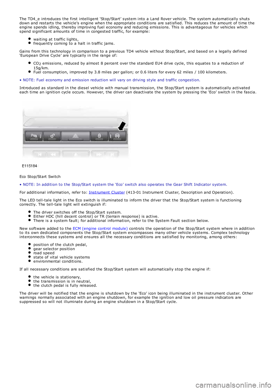
Int roduced as s tandard i n t he dies el vehicle wit h manual trans mi s si on, t he St op/Start sys tem is aut omati cal ly act ivatedeach ti me an i gni ti on cycl e occurs . However, t he driver can deact ivate the s ys tem by pres si ng t he ‘Eco’ s wi tch i n the fas ci a.
Eco Stop/St art Swi tch
• NOTE: In addi ti on t o t he Stop/St art s yst em the ‘Eco’ s wit ch als o operates the Gear Shift Indicator s yst em.
For addit ional informat ion, refer t o: Ins t rument Clus ter (413-01 Inst rument Cl us t er, Des cript ion and Operat ion).
The LED t el l-tal e li ght in t he Eco s wit ch is i ll uminated to inform t he dri ver t hat the St op/St art s yst em i s funct ioningcorrect ly. The tel l-tale li ght wi ll exti ngui sh if:
The dri ver s wi tches off t he Stop/St art s ys tem.Eit her HDC (hi ll decent cont rol ) or TR (terrain res pons e) is act ive.There i s a s ys tem fault ; for addit ional informati on, refer t o t he Sys t em Fault s ect ion bel ow.
New s oft ware added t o t he ECM (engine cont rol module) controls t he operati on of the St op/St art s yst em where i n addi ti ont o it s own dedicated component s t he Stop/Start sys tem encompas s es many other vehi cl e s yst ems . Complex t echnologyint erconnects thes e s ys t ems and ens ures all t he neces s ary condi ti ons are s ati s fi ed by monit oring, among ot hers :
posi ti on of the cl ut ch pedal ,gear s elect or pos it ionroad s peeds tat e of vit al vehicle sys temsenvi ronmental condi ti ons .
If al l neces sary condi ti ons are s ati sfied the St op/Start s ys t em wi ll automat icall y stop t he engine i f:
t he vehi cl e is st ati onary,t he trans mi s si on is in neutral,t he cl utch pedal i s ful ly releas ed.
The dri ver wi ll be not ifi ed t hat t he engine i s s hut down by t he ‘Eco’ i con bei ng il lumi nat ed in the i nst rument clus t er. Ot herwarni ngs normall y ass ociat ed wit h an engine s hutdown, for example the i gni ti on and low oil pres s ure i ndi cat ors ares uppress ed s o wi ll not il lumi nat e duri ng an engine s hutdown i n a St op/Start cycle.
Page 1107 of 3229
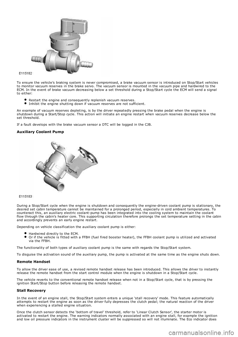
To ens ure t he vehi cl e’s braki ng s ys t em i s never compromi sed, a brake vacuum s ens or is int roduced on Stop/St art vehiclest o monit or vacuum reserves in t he brake s ervo. The vacuum sens or is mount ed in the vacuum pipe and hardwi red to t heECM. In the event of brake vacuum decreas ing below a s et threshold during a Stop/St art cycl e t he ECM wi ll s end a s ignalt o eit her:
Rest art t he engine and consequentl y replenis h vacuum reserves .Inhi bi t t he engi ne s hut ti ng down if vacuum res erves are not s uffi ci ent.
An example of vacuum res erves deplet ing, is by t he dri ver repeat edly pres s ing t he brake pedal when the engine iss hut down duri ng a St art/Stop cycle. This acti on wil l init iat e an engine res tart when vacuum reserves decreas e below thes et thres hold.
If a fault develops wi th the brake vacuum s ensor a DTC wil l be logged in the CJB.
Auxiliary Coolant Pump
Duri ng a St op/Start cycle when the engine i s s hutdown and consequent ly the engine-driven coolant pump is st ati onary, thedesi red s et cabi n t emperature cannot be mai ntai ned for a prol onged period, especially in col d ambient t emperatures . Tocount eract this , an auxil iary el ect ri c cool ant -pump has been integrat ed i nt o t he cool ing s ys tem to maint ain t he cool antfl ow t hrough t he cabi n’s heat er core. Thi s s upporti ng ci rculat ion t herefore prol ongs t he s et temperat ure set ti ng in the cabinand accordi ngl y prevents an early engine res tart.
Dependi ng on vehi cl e clas s ifi cat ion the auxil iary coolant pump i s eit her:
Hardwi red di rectl y to the ECM.Or if t he vehicle i s fit ted wi th a FFBH (fuel fi red boos ter heat er), t he FFBH coolant pump i s uti li zed and act ivatedvia t he FFBH.
The functi onal it y of bot h t ypes of auxil iary coolant pump i s t he s ame wi th regards the Stop/St art s ys tem.
To dis guis e t he acti vat ion s ound of the auxil iary pump, t he pump i s acti vat ed at the same ti me as t he engine s huts down.
Remote Handset
To all ow t he dri ver eas e of use, a revis ed remot e handset releas e has been introduced. Thi s all ows t he driver t o ins t ant lyrel eas e t he remote hands et from t he s tart cont rol module when t he engine i s s hut down in a Stop/Start cycle.
The vehi cl e reverts t o t he conventi onal remote hands et releas e when not in a Stop/Start cycle, that i s by pres s ing t heignit ion St art /St op butt on before rel eas i ng the remote hands et.
Stall Recovery
In the event of an engi ne s tal l, t he Stop/St art s ys tem ent ers a unique ‘s t al l recovery’ mode. This feature aut omat ical lyatt empts to res tart the engine as soon as t he driver full y depres ses t he clut ch pedal; t he natural react ion of t he dri verwhen experiencing a s t alled engi ne si tuat ion.
Once the cl utch s ensor detects the ‘bot t om of t ravel’ threshold, refer to ‘Linear Clut ch Sens or’, t he s t arter mot or isact ivat ed to res tart the engine. The warni ng indicat ors normal ly as s oci ated wi th an engi ne s tal l, for example the i gni ti onand low oil pres s ure i ndi cat ors i n t he ins t rument clus ter wil l be s uppress ed s o wi ll not il lumi nat e. The Eco indicator does