2006 LAND ROVER FRELANDER 2 engine oil
[x] Cancel search: engine oilPage 1202 of 3229
12-Res trai nts Cont rol Module (RCM)
13-Knock sens ors (2 off)
14-Fuel rail t emperature/pres s ure s ens or15-Clockspring
16-Terrain respons e cont rol module
17-Trans mis s ion Cont rol Module (TCM)18-ABS module
19-Diagnos ti c socket
20-CJB
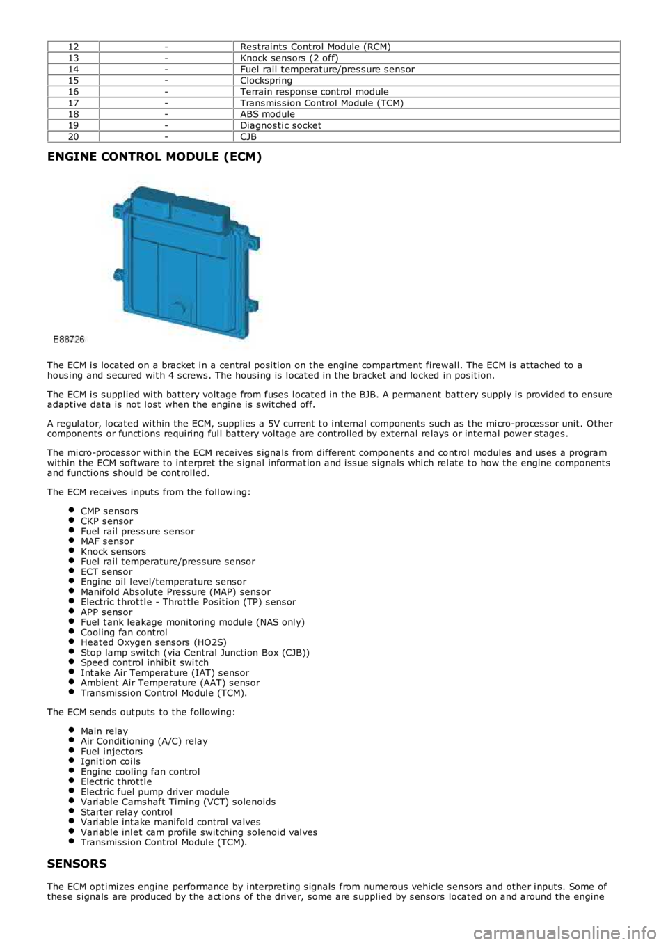
ENGINE CONTROL MODULE (ECM)
The ECM i s located on a bracket i n a central pos i ti on on the engi ne compartment firewal l. The ECM is at tached to ahous i ng and s ecured wit h 4 s crews . The hous i ng is l ocat ed in the bracket and locked in pos it ion.
The ECM i s s uppl ied wi th bat tery volt age from fuses l ocat ed in the BJB. A permanent batt ery s upply i s provided t o ens ureadapt ive dat a is not l ost when the engine i s s wit ched off.
A regul ator, locat ed wi thin the ECM, s upplies a 5V current t o i nt ernal components such as t he mi cro-proces s or unit . Ot hercomponents or funct ions requi ri ng ful l bat tery vol tage are cont rol led by ext ernal relays or int ernal power s t ages .
The mi cro-proces sor wi thi n the ECM receives s ignals from different component s and cont rol modules and us es a programwit hin the ECM software t o int erpret t he s ignal informat ion and i ss ue s ignals whi ch rel at e t o how the engine component sand functi ons should be cont rol led.
The ECM recei ves i nput s from the foll owing:
CMP s ensorsCKP s ensorFuel rail pres s ure s ensorMAF s ensorKnock s ens orsFuel rail t emperature/pres s ure s ensorECT s ens orEngi ne oil l evel/t emperature s ens orManifol d Abs olute Pres sure (MAP) sens orElectric t hrot tl e - Throt tl e Posi ti on (TP) s ens orAPP s ens orFuel t ank leakage monit oring modul e (NAS onl y)Cooling fan controlHeated Oxygen s ens ors (HO2S)Stop lamp s wi tch (via Central Juncti on Box (CJB))Speed cont rol inhibi t swi tchInt ake Air Temperat ure (IAT) s ens orAmbient Air Temperat ure (AAT) s ens orTrans mis s ion Cont rol Modul e (TCM).
The ECM s ends out puts to t he followi ng:
Main relayAir Condit ioning (A/C) relayFuel i njectorsIgni ti on coi lsEngi ne cool ing fan cont rolElectric t hrot tl eElectric fuel pump driver moduleVari abl e Cams haft Timing (VCT) s olenoidsStarter rel ay cont rolVari abl e int ake manifol d control valvesVari abl e inl et cam profile swit ching sol enoi d val vesTrans mis s ion Cont rol Modul e (TCM).
SENSORS
The ECM opt imi zes engine performance by interpreti ng s ignals from numerous vehicle sens ors and ot her i nput s. Some oft hes e s ignals are produced by t he act ions of t he dri ver, some are s uppli ed by s ens ors locat ed on and around t he engine
Page 1206 of 3229
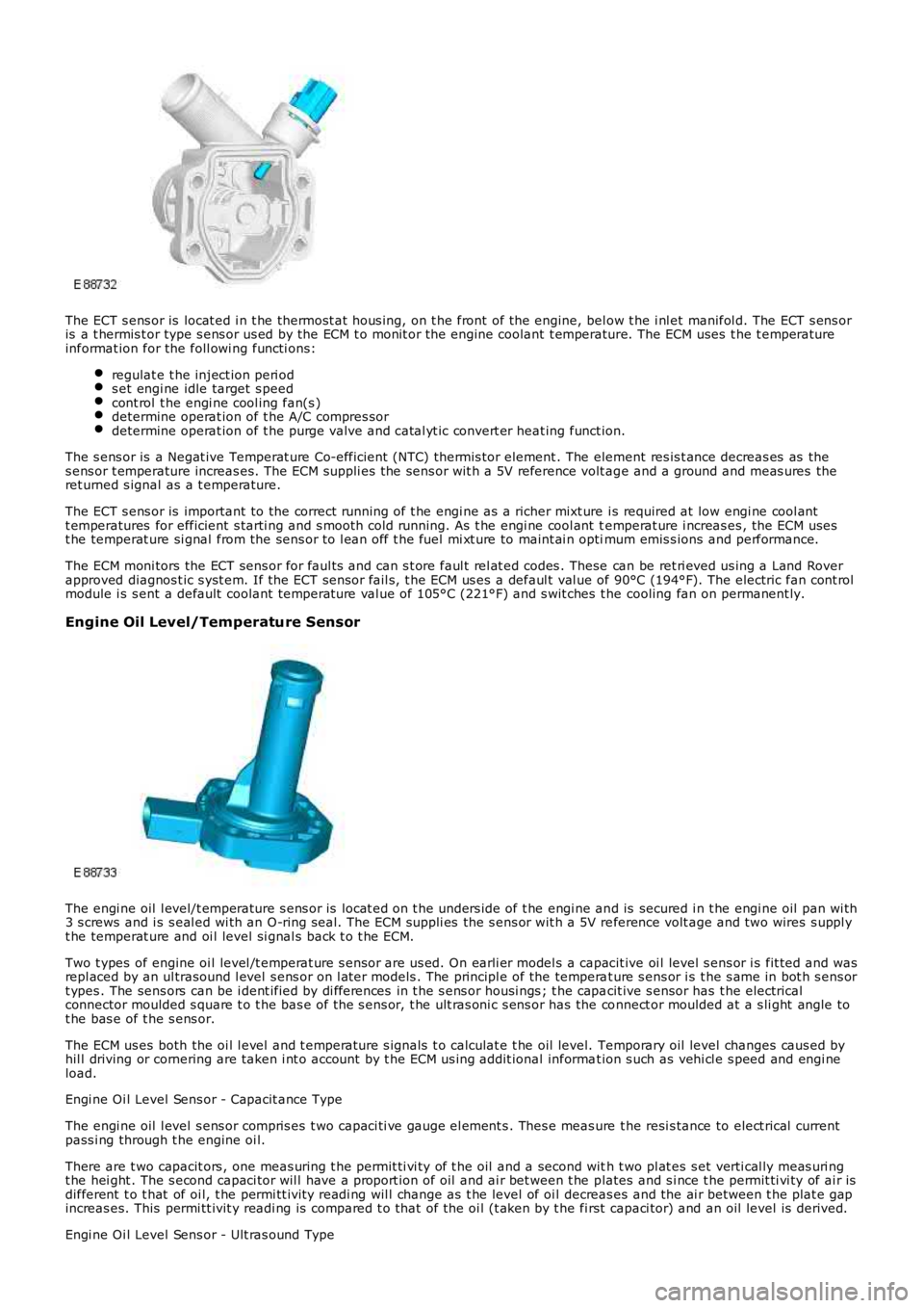
The ECT s ens or is locat ed i n t he thermost at hous ing, on t he front of the engine, below t he i nl et manifol d. The ECT s ens oris a t hermis t or type s ens or us ed by the ECM t o monit or the engine coolant t emperature. The ECM uses t he t emperatureinformat ion for the foll owi ng functi ons:
regulat e t he inject ion peri ods et engi ne idle target s peedcont rol t he engi ne cool ing fan(s )determine operat ion of t he A/C compres sordetermine operat ion of t he purge valve and catal yt ic convert er heat ing funct ion.
The s ens or is a Negat ive Temperat ure Co-efficient (NTC) thermis tor element . The element res is t ance decreas es as thes ens or t emperature increas es. The ECM suppli es the sens or wit h a 5V reference volt age and a ground and meas ures theret urned s ignal as a t emperature.
The ECT s ens or is important to the correct running of t he engi ne as a richer mixt ure i s required at low engi ne cool antt emperatures for efficient s tarti ng and s mooth cold running. As t he engi ne cool ant temperat ure i ncreas es , the ECM usest he temperat ure si gnal from the sens or to l ean off t he fuel mi xt ure to maint ai n optimum emis s ions and performance.
The ECM moni tors the ECT sens or for faul ts and can s t ore faul t rel at ed codes . These can be ret ri eved us ing a Land Roverapproved diagnos t ic s yst em. If the ECT sens or fail s, t he ECM us es a defaul t val ue of 90°C (194°F). The electric fan cont rolmodule i s s ent a default coolant temperat ure val ue of 105°C (221°F) and s wit ches t he cooling fan on permanent ly.
Engine Oil Level/Temperature Sensor
The engi ne oil l evel/t emperature s ens or is locat ed on t he unders ide of t he engi ne and is secured i n t he engi ne oil pan wi th3 s crews and i s s eal ed wi th an O-ring s eal. The ECM suppli es the s ens or wit h a 5V reference volt age and two wires s uppl yt he temperat ure and oi l level si gnal s back t o t he ECM.
Two t ypes of engine oi l level /t emperat ure s ensor are us ed. On earli er model s a capacit ive oi l level s ens or i s fit ted and wasrepl aced by an ul trasound l evel s ens or on l at er models . The principl e of the temperat ure s ens or i s t he s ame in bot h s ens ort ypes . The sens ors can be i dent ified by di fferences in t he s ens or housi ngs ; t he capacit ive s ensor has t he electricalconnector moulded s quare t o t he bas e of the s ens or, t he ult ras oni c s ens or has the connect or moulded at a s li ght angle tot he bas e of t he s ens or.
The ECM us es both the oi l l evel and t emperature s ignals t o calculat e t he oil level. Temporary oil level changes caus ed byhil l driving or cornering are taken i nt o account by t he ECM us ing addit ional informat ion s uch as vehi cl e s peed and engi neload.
Engi ne Oi l Level Sens or - Capacit ance Type
The engi ne oil l evel s ens or compris es t wo capaci ti ve gauge el ement s . Thes e meas ure the resi s tance to elect rical currentpass i ng through t he engine oi l.
There are t wo capacit ors , one meas uring t he permit ti vi ty of t he oil and a second with t wo pl at es s et verti cal ly meas uri ngt he hei ght . The s econd capaci tor wil l have a proport ion of oil and ai r bet ween t he plates and s i nce t he permit ti vi ty of ai r isdifferent t o t hat of oi l, t he permi tt ivit y readi ng wil l change as t he level of oi l decreas es and the ai r between t he plat e gapincreas es. This permi tt ivit y readi ng is compared t o t hat of the oi l (t aken by t he first capaci tor) and an oil level is derived.
Engi ne Oi l Level Sens or - Ult ras ound Type
Page 1207 of 3229
The engi ne oil l evel s ens or us es an ult ras oni c puls e, which is refl ect ed back from the s urface of t he oil . The ti me i t takesfor t his s i gnal t o ret urn t o t he s ensor i s turned int o a PW M s ignal and is s ent to the ECM. The ECM det ermi nes the ti met aken for the ul trasonic pul se si gnal t o be recei ved and calculat es it i nto an oil level fi gure.
Engi ne Oi l Temperat ure Sens or
The engi ne oil t emperature s ensor i s a Pos it ive Temperat ure Co-effi ci ent (PTC) thermis t or el ement . The element res i st anceincreas es as t he sens or temperat ure decreas es. The ECM s uppli es t he sens or wit h a 5V reference vol tage and a ground andmeas ures t he ret urned s ignal as a t emperature. A low oil temperature wil l res ult in a l ow volt age bei ng ret urned t o t heECM and hi gh oil temperature wil l ret urn a hi gh volt age reading.
The ECM moni tors the engine oi l level/temperat ure sens or for fault s and can s tore faul t rel at ed codes . These can beret ri eved us i ng a Land Rover approved diagnos t ic s ys tem. If the sens or fail s , the ECM us es t he engine cool ant temperat ures ens or s ignal val ue as a s ubst it ute.
Manifold Absolute Pressure (MAP) Sensor
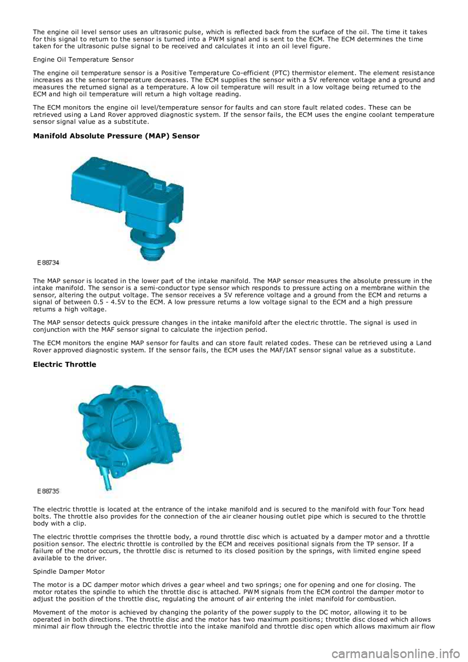
The MAP s ensor i s located i n t he lower part of t he int ake manifol d. The MAP s ens or meas ures t he abs olut e pres s ure in t heint ake manifol d. The sens or is a semi -conduct or type s ens or which responds t o pres s ure acti ng on a membrane wi thin thes ens or, al tering t he output volt age. The s ens or receives a 5V reference vol tage and a ground from t he ECM and returns as ignal of bet ween 0.5 - 4.5V t o t he ECM. A low pres sure ret urns a low vol tage s ignal to the ECM and a high press ureret urns a hi gh volt age.
The MAP s ensor det ect s quick pres s ure changes i n t he int ake mani fol d aft er the el ectri c thrott le. The s ignal is us ed inconjunct ion wi th the MAF sens or si gnal t o calculate the injecti on peri od.
The ECM moni tors the engine MAP s ens or for faul ts and can st ore fault related codes. Thes e can be ret ri eved us i ng a LandRover approved diagnost ic sys tem. If t he s ens or fai ls , the ECM uses t he MAF/IAT s ensor s i gnal value as a subs ti tut e.
Electric Throttle
The electric t hrot tl e is locat ed at t he entrance of t he int ake manifol d and is secured t o t he manifold wit h four Torx headbolt s. The t hrot tl e als o provi des for t he connect ion of t he air cleaner hous ing out let pipe which is secured t o t he t hrott lebody wit h a cl ip.
The electric t hrot tl e compri ses t he t hrott le body, a round throt t le di sc whi ch is act uat ed by a damper mot or and a thrott leposi ti on s ens or. The el ect ri c thrott le is control led by the ECM and recei ves pos i ti onal s ignals from the TP s ens or. If afai lure of the mot or occurs , t he thrott le di s c is returned to it s cl osed pos it ion by the s prings, wi th li mit ed engine s peedavai lable to the driver.
Spindle Damper Mot or
The mot or i s a DC damper motor which drives a gear wheel and t wo s pri ngs ; one for opening and one for cl osi ng. Themot or rotat es the spi ndl e t o which t he t hrott le dis c is at t ached. PW M s i gnals from the ECM control the damper mot or t oadjus t the pos it ion of t he t hrott le dis c, regul ati ng the amount of air ent ering the i nlet manifold for combus ti on.
Movement of t he mot or is achieved by changing t he polarit y of the power s uppl y to the DC mot or, all owing i t to beoperated in bot h direct ions . The throt tl e dis c and t he mot or has two maxi mum pos it ions ; t hrott le di s c cl osed which all owsmi ni mal air flow t hrough t he electric t hrot tl e int o t he int ake manifol d and t hrott le dis c open which all ows maximum air flow
Page 1209 of 3229
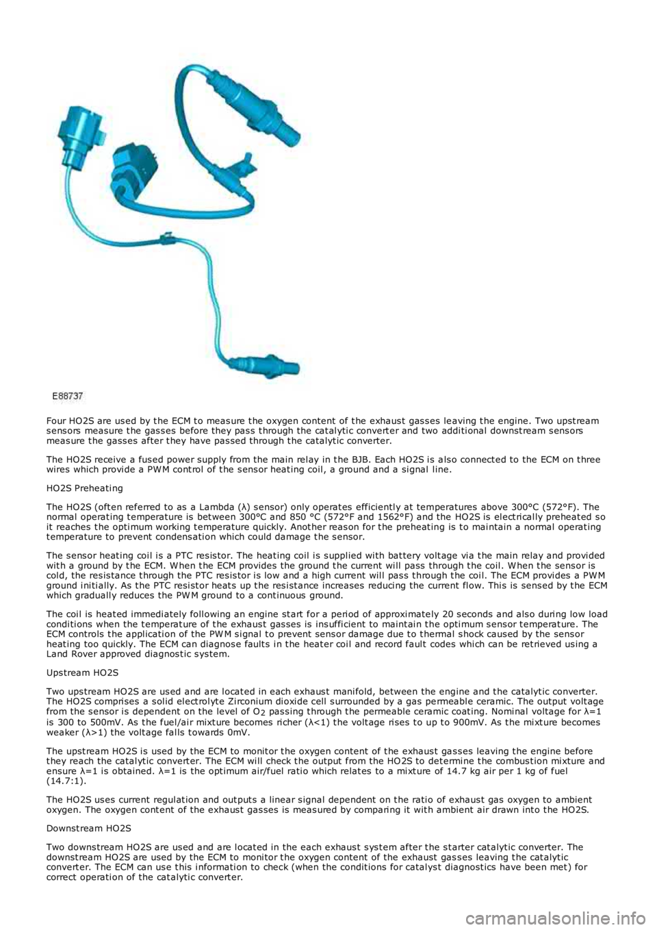
Four HO2S are us ed by t he ECM t o meas ure t he oxygen content of t he exhaus t gas s es leaving t he engine. Two upst reams ens ors measure t he gas s es before they pas s t hrough the cat al yti c convert er and two addi ti onal downst ream s ens orsmeas ure t he gass es after t hey have pas sed through t he catalyt ic converter.
The HO2S receive a fus ed power supply from t he main rel ay in t he BJB. Each HO2S i s als o connect ed to the ECM on t hreewires which provi de a PW M cont rol of t he s ens or heat ing coil , a ground and a si gnal l ine.
HO2S Preheati ng
The HO2S (oft en referred to as a Lambda (λ) s ensor) only operat es efficientl y at temperatures above 300°C (572°F). Thenormal operat ing t emperature is bet ween 300°C and 850 °C (572°F and 1562°F) and the HO2S is el ect ri cal ly preheat ed s oit reaches t he opti mum working t emperature quickly. Anot her reas on for t he preheat ing is t o mai ntain a normal operat ingt emperature to prevent condens ati on which could damage t he s ensor.
The s ens or heat ing coi l i s a PTC res is tor. The heat ing coil i s s uppl ied wi th bat tery volt age vi a t he main relay and provi dedwit h a ground by t he ECM. W hen t he ECM provides t he ground t he current wi ll pass through t he coil . W hen t he sens or iscol d, the res is tance t hrough the PTC res is tor i s low and a high current wil l pas s t hrough t he coi l. The ECM provi des a PW Mground i ni ti ally. As t he PTC resi st or heat s up t he res i st ance increases reduci ng the current fl ow. Thi s is sens ed by t he ECMwhich graduall y reduces the PW M ground to a cont inuous ground.
The coi l is heat ed immedi ately foll owing an engine st art for a peri od of approxi mately 20 s econds and als o duri ng low loadcondi ti ons when the t emperat ure of t he exhaus t gas s es is ins uffi cient to maint ai n t he opti mum s ens or t emperat ure. TheECM controls t he appl icati on of the PW M s i gnal t o prevent sens or damage due t o t hermal s hock caus ed by the sens orheat ing too quickly. The ECM can diagnos e fault s i n t he heat er coi l and record faul t codes whi ch can be ret rieved us ing aLand Rover approved diagnos t ic s ys tem.
Ups tream HO2S
Two ups tream HO2S are us ed and are l ocat ed in each exhaus t mani fold, between the engine and t he catalyt ic converter.The HO2S compri ses a s ol id el ect rol yt e Zi rconium di oxi de cel l s urrounded by a gas permeabl e ceramic. The output volt agefrom the s ensor i s dependent on the level of O2 pas s ing t hrough t he permeable ceramic coat ing. Nomi nal volt age for λ=1is 300 to 500mV. As t he fuel /ai r mixt ure becomes ri cher (λ<1) t he volt age ri ses t o up t o 900mV. As t he mi xt ure becomesweaker (λ>1) the volt age fal ls t owards 0mV.
The upst ream HO2S i s used by the ECM to monit or t he oxygen content of t he exhaus t gas s es leaving t he engine beforet hey reach the catal yt ic convert er. The ECM wi ll check t he output from the HO 2S to det ermi ne t he combus t ion mi xture andensure λ=1 i s obtained. λ=1 is the opt imum air/fuel rati o which relat es to a mi xt ure of 14.7 kg air per 1 kg of fuel(14.7:1).
The HO2S us es current regul at ion and out put s a linear s ignal dependent on t he rati o of exhaus t gas oxygen to ambientoxygen. The oxygen cont ent of the exhaus t gas ses is meas ured by compari ng it wit h ambient air drawn int o t he HO2S.
Downst ream HO2S
Two downs tream HO2S are us ed and are l ocat ed in the each exhaus t s ys t em after t he s tarter cat alyt ic converter. Thedownst ream HO2S are used by the ECM to moni tor t he oxygen content of the exhaust gass es leaving t he cat alyt icconvert er. The ECM can us e t his i nformati on to check (when the condit ions for catal ys t diagnost ics have been met ) forcorrect operati on of the cat alyti c convert er.
Page 1212 of 3229
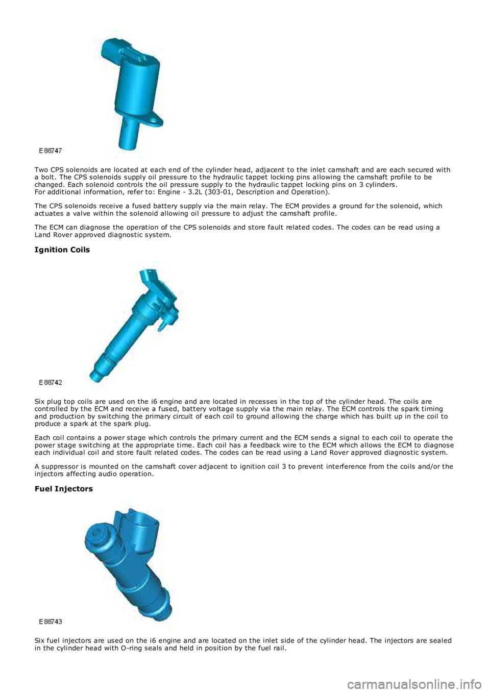
Two CPS s olenoids are located at each end of the cyli nder head, adjacent t o t he inlet cams haft and are each s ecured wi tha bolt . The CPS s olenoids s uppl y oil pres s ure t o t he hydrauli c tappet locki ng pins al lowing t he cams haft profile to bechanged. Each s olenoid controls t he oil press ure supply to the hydrauli c tappet locking pins on 3 cyl inders .For addit ional informat ion, refer t o: Engi ne - 3.2L (303-01, Descripti on and Operat ion).
The CPS s olenoids receive a fus ed batt ery s upply via the main relay. The ECM provides a ground for t he s ol enoi d, whichact uates a val ve wit hin t he s olenoid al lowing oi l pres sure t o adjus t the cams haft profil e.
The ECM can diagnose the operat ion of t he CPS s olenoids and s t ore faul t rel at ed codes . The codes can be read us ing aLand Rover approved diagnos t ic s ys tem.
Ignition Coils
Six pl ug top coi ls are used on the i6 engine and are located in reces s es in t he t op of the cyli nder head. The coi ls arecont rol led by t he ECM and recei ve a fus ed, bat t ery volt age s upply vi a t he main rel ay. The ECM controls t he s park t imingand product ion by swit ching the primary circuit of each coil to ground all owing t he charge which has buil t up in the coil t oproduce a s park at t he s park plug.
Each coi l contai ns a power st age which controls t he pri mary current and the ECM s ends a si gnal t o each coi l to operat e t hepower st age s wit chi ng at the appropriate ti me. Each coil has a feedback wi re to t he ECM whi ch all ows the ECM to diagnos eeach individual coi l and st ore fault related codes. The codes can be read us ing a Land Rover approved diagnos t ic s yst em.
A s uppres sor i s mounted on the cams haft cover adjacent to ignit ion coil 3 t o prevent int erference from t he coi ls and/or t heinject ors affecti ng audi o operat ion.
Fuel Injectors
Six fuel injectors are us ed on the i 6 engine and are located on t he i nl et s ide of t he cyl inder head. The inject ors are s eal edin the cyli nder head wi th O -ring s eals and held in pos it ion by the fuel rail .
Page 1215 of 3229
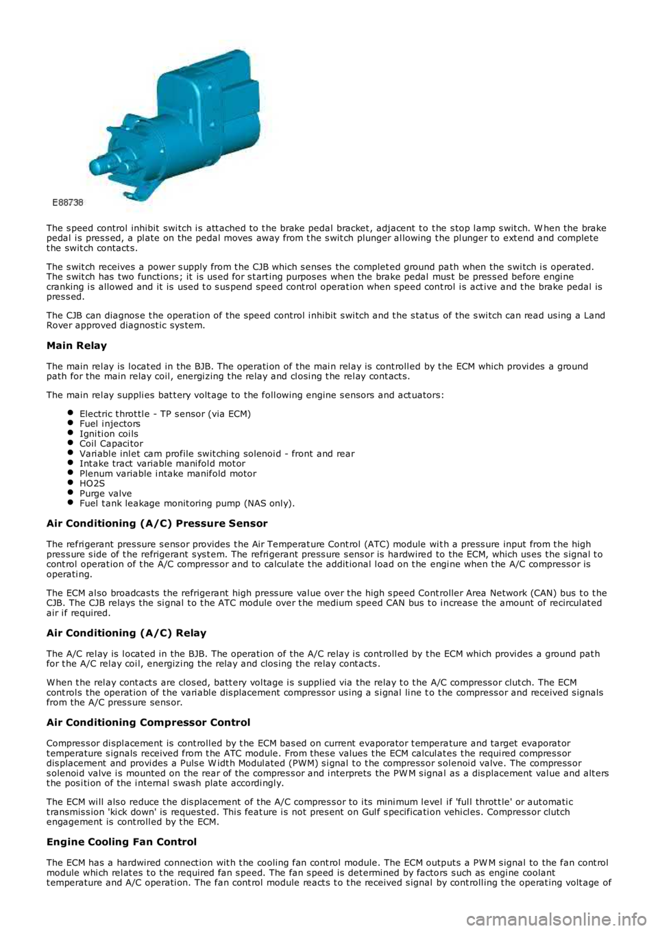
The s peed control inhibit swi tch i s att ached to t he brake pedal bracket , adjacent t o t he s top l amp s wit ch. W hen the brakepedal i s pres s ed, a pl ate on the pedal moves away from t he s wit ch plunger al lowing the pl unger to ext end and completet he swit ch contact s.
The s wit ch receives a power s upply from t he CJB which s enses the complet ed ground path when the s wi tch i s operated.The s wit ch has two functi ons ; it is us ed for s t art ing purpos es when the brake pedal mus t be pres s ed before engi necranking i s allowed and it is used t o s us pend speed cont rol operat ion when s peed cont rol i s act ive and t he brake pedal ispres s ed.
The CJB can diagnos e t he operat ion of t he speed control i nhibit s wi tch and t he s tat us of the s wi tch can read us ing a LandRover approved diagnost ic sys tem.
Main Relay
The main rel ay is l ocat ed in the BJB. The operati on of the mai n rel ay is cont roll ed by t he ECM which provi des a groundpath for the main relay coil , energi zing t he rel ay and cl osi ng t he rel ay cont act s.
The main rel ay suppli es bat t ery volt age to the foll owing engine s ensors and act uators:
Electric t hrot tl e - TP s ensor (via ECM)Fuel i njectorsIgni ti on coi lsCoil Capaci torVari abl e inl et cam profile swit ching sol enoi d - front and rearInt ake tract variable mani fol d mot orPlenum variable i ntake manifold motorHO2SPurge valveFuel t ank leakage monit oring pump (NAS onl y).
Air Conditioning (A/C) Pressure Sensor
The refri gerant pres sure s ens or provides t he Air Temperat ure Cont rol (ATC) module wit h a press ure input from t he highpres s ure s ide of t he refrigerant s ys t em. The refri gerant press ure s ens or is hardwired to the ECM, which us es t he s ignal t ocont rol operat ion of t he A/C compress or and to cal cul at e t he addit ional l oad on t he engi ne when t he A/C compress or isoperati ng.
The ECM al so broadcas ts the refrigerant high press ure val ue over t he high s peed Controller Area Network (CAN) bus t o t heCJB. The CJB relays the si gnal t o t he ATC module over t he medium speed CAN bus t o i ncreas e the amount of recircul at edair i f required.
Air Conditioning (A/C) Relay
The A/C rel ay is l ocat ed in the BJB. The operati on of the A/C relay i s cont roll ed by t he ECM whi ch provi des a ground pat hfor t he A/C rel ay coi l, energizi ng the relay and clos ing the relay cont acts .
W hen t he rel ay cont act s are clos ed, batt ery vol tage i s s uppl ied via the relay t o t he A/C compress or clut ch. The ECMcont rol s the operat ion of t he vari abl e dis placement compress or us ing a s i gnal li ne to t he compress or and received s ignalsfrom the A/C pres s ure sens or.
Air Conditioning Compressor Control
Compres s or di spl acement is cont roll ed by t he ECM bas ed on current evaporator t emperature and target evaporat ort emperature s ignals received from t he ATC module. From thes e values t he ECM calcul ates t he requi red compres s ordis placement and provi des a Puls e W idt h Modul ated (PW M) s i gnal t o t he compress or s olenoi d valve. The compress ors olenoi d valve i s mounted on the rear of t he compres s or and i nterprets the PW M s ignal as a dis placement val ue and alt erst he pos i ti on of the i nternal s wash plate accordi ngl y.
The ECM wi ll als o reduce t he dis placement of the A/C compres s or to i ts mini mum l evel i f 'ful l throt t le' or aut omati ct ransmis s ion 'ki ck down' is request ed. Thi s feat ure i s not pres ent on Gul f s pecificati on vehi cl es. Compress or clutchengagement is cont roll ed by t he ECM.
Engine Cooling Fan Control
The ECM has a hardwired connect ion wit h t he cooli ng fan cont rol module. The ECM output s a PW M s ignal to the fan cont rolmodule whi ch rel at es t o t he required fan s peed. The fan s peed is det ermi ned by factors s uch as engi ne coolantt emperature and A/C operati on. The fan cont rol module react s t o t he received s ignal by cont roll ing t he operat ing volt age of
Page 1216 of 3229
t he fan mot ors . The fan cont rol module confi rms the fan s peed operati on on the same connect ion back t o t he ECM.
Starter Motor Relay
The s tarter mot or relay i s located in t he BJB. The operat ion of t he s tarter mot or relay i s cont rol led by t he ECM whi chprovides a ground pat h for the relay coil , energi zing t he rel ay and cl osi ng t he relay contact s. W hen the relay contacts areclos ed, bat tery vol tage i s s uppl ied, vi a t he s tarter mot or relay, to the st art er modul e s olenoid coil . The st art er s ol enoi d isenergized and connects the s t art er motor wit h a direct batt ery feed t o operate the st art er motor.
Once the engi ne has st art ed, the ECM removes the st art er motor relay ground, opening the relay contacts and t erminati ngt he bat t ery feed to the s t art er s olenoid, which i n t urn s t ops the operat ion of t he starter mot or.For addit ional informat ion, refer t o: Starti ng Sys t em - 3.2L (303-06, Des cript ion and Operat ion).
Fuel Pump Module
The fuel pump i s cont rol led by t he FPDM whi ch in t urn is control led by the ECM. The FPDM provi des pos it ive and negati vefeeds t o t he fuel pump mot or which is cont roll ed wit h a PW M out put . The fuel pump i s run for 2 s econds t o prime the fuels ys t em once igni ti on on is sens ed by t he ECM.For addit ional informat ion, refer t o: Fuel Tank and Lines (310-01, Des cri pt ion and Operati on).
Malfunction Indicator Lamp (MIL)
The MIL is locat ed in the ins trument cl us t er and is i lluminated by a CAN mes s age from t he ECM when an emis s ion relatedfaul t occurs . The ECM als o ill uminat es the MIL when reques t ed to do s o by t he TCM and t o perform a bulb check when theignit ion is s wi tched on. There is no MIL ill uminat ion for non emis si on rel ated engine management fault s . All engine faul tsare recorded wit h a Diagnos t ic Troubl e Code (DTC) whi ch can be ret rieved us ing a Land Rover approved di agnos ti c s yst em.For addit ional informat ion, refer t o: Electroni c Engi ne Controls - 3.2L (303-14, Diagnos is and Tes ti ng).
Generator Feedback Signal
The generator has a Local Interconnect Net work (LIN) bus connect ion direct to t he ECM. The LIN bus is us ed by t he ECM t oreques t vol tage for bat tery charging and t o monit or the fault s t at us of t he generat or.
PRINCIPLES OF OPERATION
Starting Process
The ECM wi ll only al low engine crank, s park and i njector functi ons when the foll owing condi ti ons are met:
A hardwi red Park/Neutral si gnal i s received from the Trans mi ss i on Cont rol Module (TCM)A hardwi red ignit ion s ignal is recei ved from t he CJBA hardwi red crank reques t s ignal is recei ved from t he CJBEncrypt ed data exchange bet ween t he ins trument cl ust er and the ECM is verifi ed.
Before the CJB will s end t he hardwired igni ti on si gnal , it mus t s ati s factori ly complet e t he fol lowi ng:
Exchange encrypt ed data wit h t he s tart control modul e t o vali dat e t he remot e handset.
Addit ional ly, before the CJB will s end t he hardwired crank reques t s ignal i t mus t receive t he fol lowing si gnal s:
Brake s ignal from t he s peed cont rol inhibi t s wit chHardwi red t rans mis s ion in Park (P) or Neutral (N) s ignal from t he s elector lever assembl y.
W i th the remote hands et ins ert ed in the s t art cont rol module and the st op/s tart button is press ed, the st art controlmodule i s sues bat tery vol tage hi gh si gnal on t he LIN bus connecti on to the CJB and the fuel pump i s run for 2 s econds t opri me t he fuel s yst em. The CJB us es this si gnal t oget her wit h t he s top l amp s wit ch signal and is sues a crank requestmes s age on the hi gh s peed CAN bus to the ECM.
The ECM, on receipt of t he crank request mess age, then provides a power and ground supply t o t he s tarter rel ay in theBJB, clos ing the relay contacts . Batt ery volt age is suppli ed via a fus e t hrough t he st art er rel ay and is pas sed to the s t art ermot or s olenoid coi l. The coil is energi zed, clos ing t he s olenoid contacts and allowing a fuse bat tery volt age supply di rectfrom the bat tery to operat e t he s tarter mot or and crank the engine and si mult aneous ly s wi tch t he fuel pump on.
The ECM operat es the st art er motor unti l the engine st art s which i s determined by t he engine s peed exceeding apre-det ermined value.
Auto St art
The ECM has an aut o s tart functi on which all ows the engi ne to cont inue cranking i f the s t op/s tart but ton is released. Thes tarter mot or will operat e unti l the engine st art s or a pre-determined peri od of ti me has el aps ed which i s bas ed on engi necool ant t emperat ure. Low engine cool ant temperat ures al low l onger crank t imes . If the engine does not rot ate or t heengi ne s peed is l ow, the ECM removes t he power s upply and ground from t he st art er rel ay st oppi ng t he crank process .
Start Prevent ion
Operat ion of t he s tart er mot or wi ll not be all owed or wil l be int errupt ed if:
t he engi ne is runni ng and t he engi ne s peed has exceeded a predet ermined s peedt he encrypt ed data exchange bet ween the i nst rument clus t er, ECM, CJB and st art control modul e has fai led t oidenti fy the remote hands ett he gear s elector l ever is not i n t he park 'P' or neutral 'N' pos it ion. The s ignal is det ermi ned from a si gnal from theTCM and al so the t rans mi ss ion mount ed pos it ion s wit cht he brake pedal i s not pres sed.
Engine Stop Process
Page 1218 of 3229
The posi ti on of the inlet cams haft is det ermi ned by the ECM us ing s ignals from t he CKP s ens or and t he CMP s ens ors. TheECM can t hen use the VCT sol enoid val ve to cont rol t he angl e of the cams haft by controlli ng t he fl ow of oil t o t he VCT unit .
The camshaft is s ecured t o t he rot or in t he VCT unit . Oil pres s ure suppli ed to eit her s ide of t he VCT unit from t he VCTs olenoi d valve can rot ate the rotor and hence the cams haft i n eit her di recti on. The VCT sol enoi d is operat ed by t he ECMus ing PW M, hi gh frequency s wit chi ng which provi des rapid and preci se cont rol of the i nlet cams haft pos i ti on. The i nletcamshaft pos i ti on can be adjust ed wi thi n 40 degrees of cranks haft rotat ion.
Camshaft Profile Switching (CPS) Control
The inl et cams haft has , in addit ion to t he VCT control, a CPS funct ion whi ch is al so cont roll ed by t he ECM. The CPS cont rolcan vary t he val ve li ft height and durat ion of t he camshaft lobes by adjus ti ng the area of t he hydraul ic t appet whi ch act son one of t wo cam l obe profi les . The CPS cont rol is vi a t wo CPS s olenoid valves , located at each end of the i nlet cams haft.The CPS s olenoid valves cont rol t he posi ti on of hydraul ic t appet as s embli es which can be s et in one of t wo pos it ions; lowand high.
Two CPS s olenoids are us ed so that t he hydraul ic t appet s can be adjus t ed when no load i s applied, for example the camlobes are off t he hydraul ic t appet s and t he cam bas e circl e is act ing on t he t appet , thi s keeps t he s tress on components toa minimum. One CPS s ol enoi d s uppl ies oi l press ure to the hydrauli c t appet s of cyli nders 1, 2 and 4 and the s econd CPSs olenoi d s uppl ies oi l press ure to the tappet s of cylinders 3, 5 and 6.
At engi ne s tart and at low engine oi l temperat ures (below 40°C (104°F)) the ECM does not direct engine oi l pres sure t ot he hydraul ic t appet s and t herefore the hydraul ic t appet s are in t heir s pring loaded, l ow posi ti on.For addit ional informat ion, refer t o: Engi ne - 3.2L (303-01, Descripti on and Operat ion).
Ignition Control
The ECM calculat es the opt imum ignit ion ti ming bas ed on pre-programmed maps and informat ion from t he foll owings ens ors :
CKP s ensorCMP s ensorsMAF s ensorECT s ens orElectric t hrot tl e TP s ensorKnock s ens orsTCMIgni ti on coi ls .
Duri ng engi ne s tarti ng the ECM uses a fi xed ignit ion s et ti ng. W hen the engine has s tart ed and the vehicle is bei ng driven,t he ECM adjus ts the i gni ti on t imi ng accordi ngl y us ing ot her paramet ers s uch as engine s peed, l oad and temperat ure.
Once the engi ne has reached i ts normal operati ng temperature, t he ECM moni tors the si gnal s from the knock sens ors . Ifany of the cyli nders produce knocking, the i gnit ion t imi ng for t hat cyli nder wi ll be retarded unt il t he knocking has s t opped.The ignit ion is t hen gradually advanced back t o t he normal t imi ng or unt il t he knocking re-occurs .
The ECM us es informat ion from the TCM t o provide t orque l imi tat ion during t rans mis s ion s hifts . The i gni ti on ti mi ng isadjus ted t o moment ari ly reduce t he engine t orque output t o give a smoot h t rans mis s ion shi ft and reduce l oad on thet ransmis s ion.
Air Conditioning (A/C) Compressor Control
The ECM controls t he operati on of the A/C compres s or and reacts t o reques ts from t he ATC module vi a t he high s peed CANbus. The compres s or is a variable di s pl acement unit and t he ECM controls , via a sol enoi d, t he dis placement of thecompres sor t o adjus t load during cert ain driving condit ions.
Duri ng engi ne s tart-up, movi ng from a s tandst il l and under hard accelerat ion, the ECM s et s t he mi nimum dis placement oft he compress or t o reduce the effect on t he engi ne t orque output. The ECM uses i nformati on from t he ATC module, t he A/Cpres s ure s ensor, the el ect ri c t hrott le TP s ens or and the ECT sens or to det ermi ne compres sor control . The ATC modulet ransmit s climate control and driver reques ts t o t he ECM and t he ECM det ermi nes the priori ty of thes e request s overengi ne performance.