Page 1126 of 3229
Publi s hed: 11-May-2011
Engine Emission Control - I6 3.2L Petrol -
Torque SpecificationsDescriptionNmlb-ft
Crankcas e vent oil s eparator retaini ng bol ts107
Exhaus t gas recircul ati on (EGR) cooler to exhaus t manifol d bolt s2518
Page 1128 of 3229

Publi s hed: 11-May-2011
Engine Emission Control - I6 3.2L Petrol - Engine Emission Control
Diagnosi s and Tes ti ng
Principles of Operation
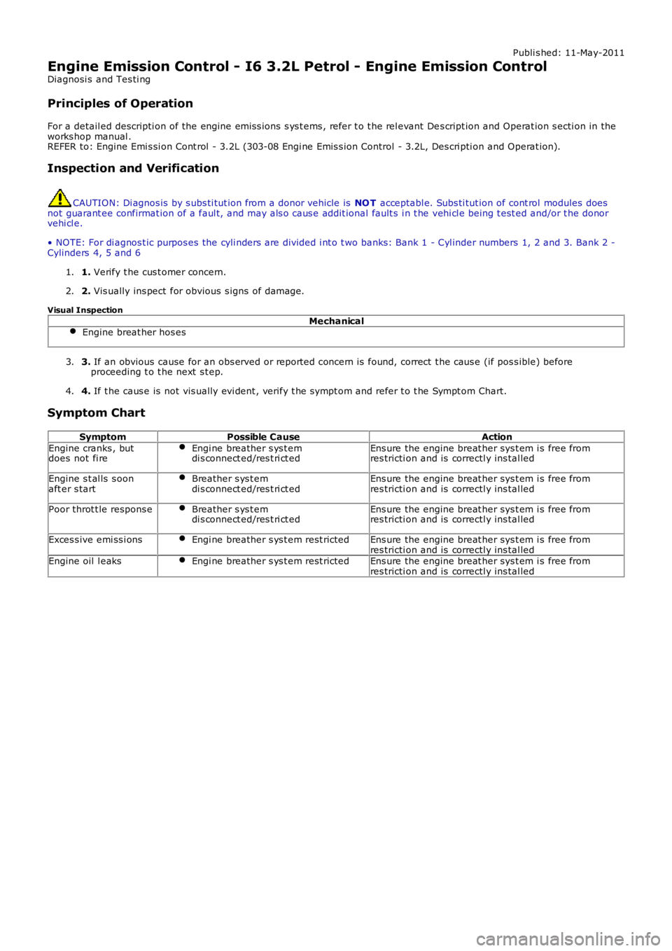
For a detail ed descripti on of the engine emis s ions s ys t ems , refer t o t he rel evant Des cript ion and Operat ion s ecti on in theworks hop manual .REFER to: Engine Emi s si on Cont rol - 3.2L (303-08 Engi ne Emis s ion Control - 3.2L, Descri pti on and Operat ion).
Inspection and Verification
CAUTION: Di agnos is by s ubs ti tut ion from a donor vehicle is NO T acceptabl e. Subs ti tut ion of cont rol modules doesnot guarant ee confirmat ion of a faul t, and may als o caus e addit ional fault s i n t he vehi cl e being t est ed and/or t he donorvehi cl e.
• NOTE: For di agnos t ic purpos es the cyli nders are divided i nt o t wo banks: Bank 1 - Cyl inder numbers 1, 2 and 3. Bank 2 -Cylinders 4, 5 and 6
1. Verify t he cus t omer concern.1.
2. Vis ually ins pect for obvious s igns of damage.2.
Visual Inspection
MechanicalEngine breat her hos es
3. If an obvious cause for an obs erved or report ed concern is found, correct t he caus e (if pos s ible) beforeproceeding t o t he next s t ep.3.
4. If t he caus e is not vis ually evi dent , verify t he sympt om and refer t o t he Sympt om Chart.4.
Symptom Chart
SymptomPossible CauseAction
Engine cranks , butdoes not fi reEngi ne breather s ys t emdi s connect ed/res t ri ct edEns ure the engine breat her sys t em i s free fromres tricti on and is correctl y ins tal led
Engine s t al ls s oonaft er s tartBreather s ys t emdi s connect ed/res t ri ct edEns ure the engine breat her sys t em i s free fromres tricti on and is correctl y ins tal led
Poor throt t le respons eBreather s ys t emdi s connect ed/res t ri ct edEns ure the engine breat her sys t em i s free fromres tricti on and is correctl y ins tal led
Exces s ive emi ss i onsEngi ne breather s ys t em rest rictedEns ure the engine breat her sys t em i s free fromres tricti on and is correctl y ins tal ledEngine oil l eaksEngi ne breather s ys t em rest rictedEns ure the engine breat her sys t em i s free fromres tricti on and is correctl y ins tal led
Page 1129 of 3229
Publi s hed: 11-May-2011
Engine Emission Control - I6 3.2L Petrol - Crankcase Vent Oil Separator
Removal and Inst all ati on
Removal
• NOTE: Removal s t eps in t his procedure may cont ain i nst all ati on det ail s.
Remove t he engi ne cover.
Refer t o: Engi ne Cover - I6 3.2L Pet rol (501-05 Int eri or Trim and
Ornament ati on, Removal and Ins tal lat ion).
1. 2.
3.
T orque:
10 Nm 4.
Page 1131 of 3229
Publi s hed: 11-May-2011
Engine Emission Control - TD4 2.2L Diesel -
Torque SpecificationsDescriptionNmlb-ft
Crankcas e vent oil s eparator97
Crankcas e vent oil s eparator, wiring harnes s bracket.107Crankcas e vent oil s eparator t o cylinder block, bracket.
M6107
M82518EGR Cooler bolt s107
EGR Cooler cros s -over pipe s ecuring bolt107
EGR Val ve inlet t ube bol ts107EGR Val ve out let t ube bol ts107
EGR Val ve nut s107
EGR Val ve screws64Exhaus t manifold heat shi el d107
Fuel fil ter brackets2518
HO2S W iring harnes s bracket86Intake manifold adaptor64
Intake manifold adaptor, wiring harnes s bracket107
Page 1132 of 3229
Publ is hed: 10-Jun-2011
Engine Emission Control - TD4 2.2L Diesel - Engine Emission Control
Des cript ion and Operat ion
COMPONENT LOCATION
ItemPart NumberDescription
1-Cams haft cover2-Posi ti ve crankcas e vent il ati on (PCV) valve
3-Crankcas e gas vent to air int ake duct
4-Oil fil ler cap5-Oil return t ube
6-Crankcas e vent oil s eparator
7-Crankcas e gas venti lat ion t ube - s howi ng fl ow direct ion
Page 1133 of 3229

ItemPart NumberDescription
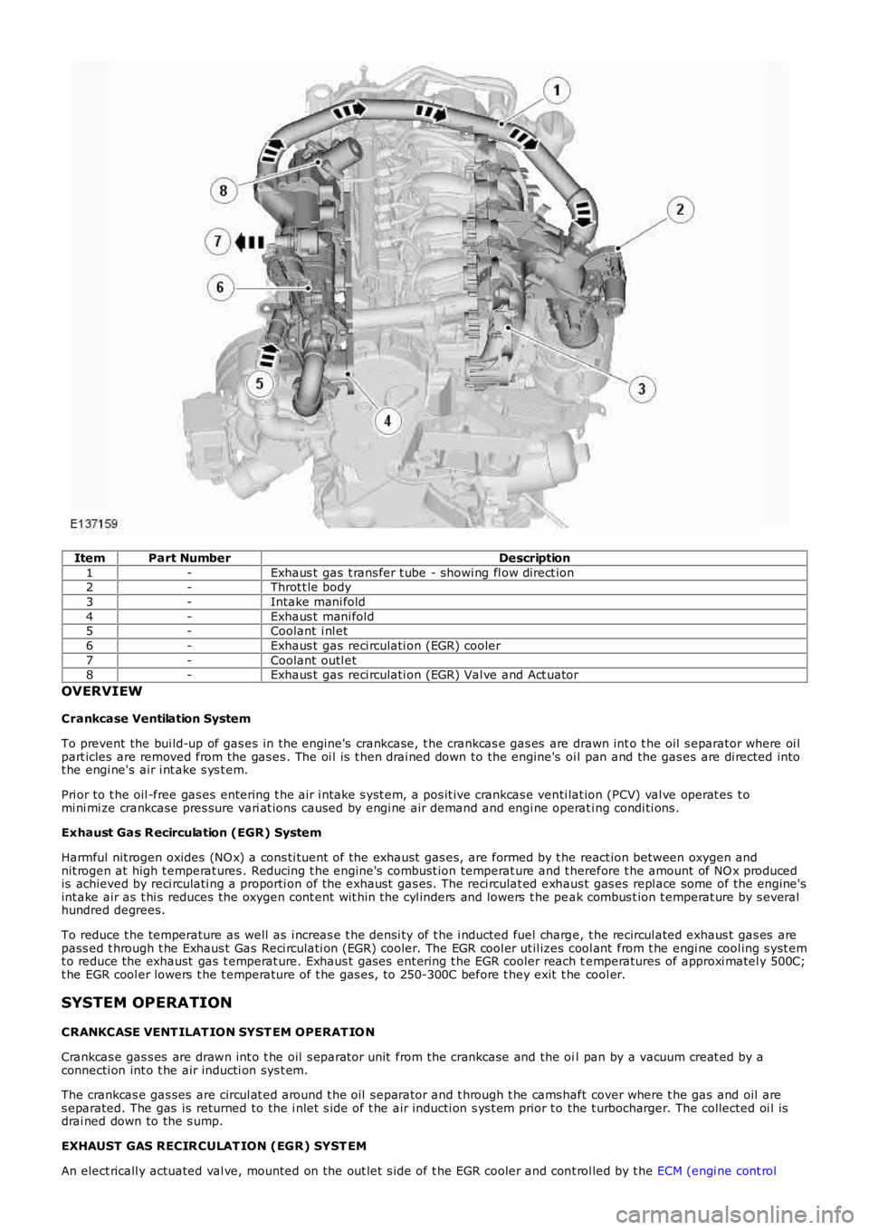
1-Exhaus t gas t rans fer t ube - showi ng fl ow direct ion2-Throt t le body
3-Intake mani fold
4-Exhaus t mani fold5-Coolant i nl et
6-Exhaus t gas reci rculati on (EGR) cooler
7-Coolant outl et8-Exhaus t gas reci rculati on (EGR) Val ve and Act uator
OVERVIEW
Crankcase Ventilation System
To prevent the bui ld-up of gas es in the engine's crankcase, t he crankcas e gas es are drawn int o t he oil s eparator where oi lpart icles are removed from the gas es . The oi l is t hen drai ned down to the engine's oi l pan and the gas es are di rected intot he engi ne's air i nt ake s ys t em.
Pri or to t he oil -free gas es entering t he air i ntake s yst em, a pos it ive crankcas e venti lat ion (PCV) val ve operat es t omi ni mi ze crankcase pres sure vari at ions caused by engi ne air demand and engi ne operati ng condi ti ons .
Exhaust Gas R ecirculation (EGR) System
Harmful nit rogen oxides (NO x) a cons ti tuent of the exhaust gas es, are formed by t he react ion between oxygen andnit rogen at high t emperat ures . Reducing t he engine's combust ion temperat ure and t herefore t he amount of NO x producedis achieved by reci rculati ng a proporti on of the exhaust gas es. The reci rculat ed exhaus t gas es repl ace some of the engine'sint ake air as t hi s reduces the oxygen cont ent wit hin t he cyl inders and lowers t he peak combus t ion t emperat ure by s everalhundred degrees.
To reduce t he temperature as well as i ncreas e t he densi ty of t he i nducted fuel charge, t he recircul ated exhaus t gas es arepass ed t hrough t he Exhaus t Gas Reci rculati on (EGR) cooler. The EGR cool er ut il izes cool ant from t he engi ne cool ing s yst emt o reduce the exhaust gas t emperat ure. Exhaus t gas es ent ering t he EGR cooler reach temperatures of approxi matel y 500C;t he EGR cool er lowers t he t emperature of t he gas es , to 250-300C before t hey exit t he cool er.
SYSTEM OPERATION
CRANKCASE VENT ILAT ION SYST EM OPERAT IO N
Crankcas e gas s es are drawn int o t he oil s eparator unit from the crankcase and the oil pan by a vacuum creat ed by aconnecti on int o t he air inducti on sys t em.
The crankcas e gas ses are circul at ed around t he oil s eparator and t hrough t he cams haft cover where t he gas and oil ares eparated. The gas is returned to the i nlet s ide of t he air inducti on s ys t em prior to the t urbocharger. The collected oi l isdrai ned down to the s ump.
EXHAUST GAS RECIR CULAT ION (EGR) SYST EM
An elect ricall y actuated val ve, mounted on the out let s ide of t he EGR cooler and cont rol led by t he ECM (engi ne cont rol
Page 1134 of 3229

module), regulates t he amount of exhaus t gas es reci rculated into the ai r int ake s ys tem. The ECM uses s i gnals fromvarious engine s ens ors and calculates a res pons e bas ed on t he embedded software algori thm t o cont rol exhaus t gasrecircul ati on. The ECM trans mi ts this cont rol s ignal t o t he valve's actuat or, which i s clos ed-loop controlled wit h t he mas sair flow (MAF) s ens or providi ng the feedback t o t he ECM.
COMPONENT DESCRIPTION
Exhaust Gas R ecirculation (EGR) Valve and Cooler Assembly
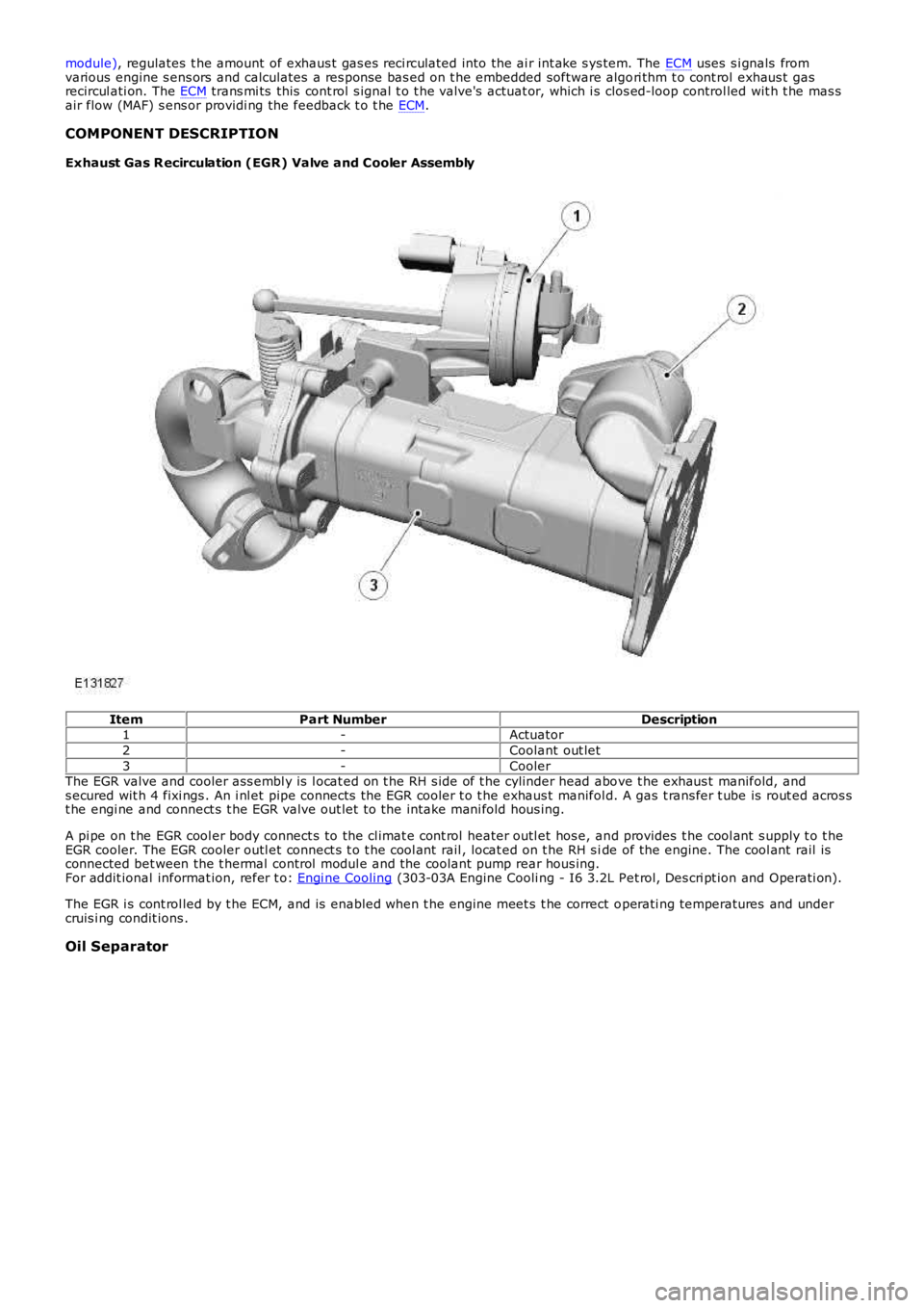
ItemPart NumberDescription1-Actuator
2-Coolant out let
3-CoolerThe EGR valve and cooler ass embl y is l ocat ed on t he RH s ide of t he cylinder head above t he exhaus t manifold, ands ecured wit h 4 fixi ngs . An i nl et pipe connects the EGR cooler t o t he exhaus t manifold. A gas t rans fer t ube is rout ed acros st he engi ne and connect s t he EGR valve out let t o the intake mani fold hous ing.
A pi pe on t he EGR cool er body connect s to the cl imat e cont rol heater outl et hos e, and provides t he cool ant s upply t o t heEGR cooler. The EGR cooler outl et connect s t o t he cool ant rail , locat ed on t he RH s ide of the engine. The cool ant rail isconnected bet ween the t hermal control modul e and the coolant pump rear hous ing.For addit ional informat ion, refer t o: Engi ne Cooling (303-03A Engine Cooli ng - I6 3.2L Pet rol, Des cri pt ion and Operati on).
The EGR i s cont rol led by t he ECM, and is enabled when t he engine meet s t he correct operati ng temperatures and undercruis i ng condit ions .
Oil Separator
Page 1135 of 3229
The crankcas e venti lati on oil s eparator i s als o connected to t he oil fil ler t ube, located at t he rear LH si de of the engine. Oi lfor repl enis hing t he s ys t em pas ses through t he oil s eparator and return hos e, and int o t he oil pan. An oil baffle pl ate i sins t al led i n t he oil pan housi ng to reduce oil aerat ion and s plas h.