2006 LAND ROVER FRELANDER 2 engine oil
[x] Cancel search: engine oilPage 1109 of 3229
Fuel fired heat er
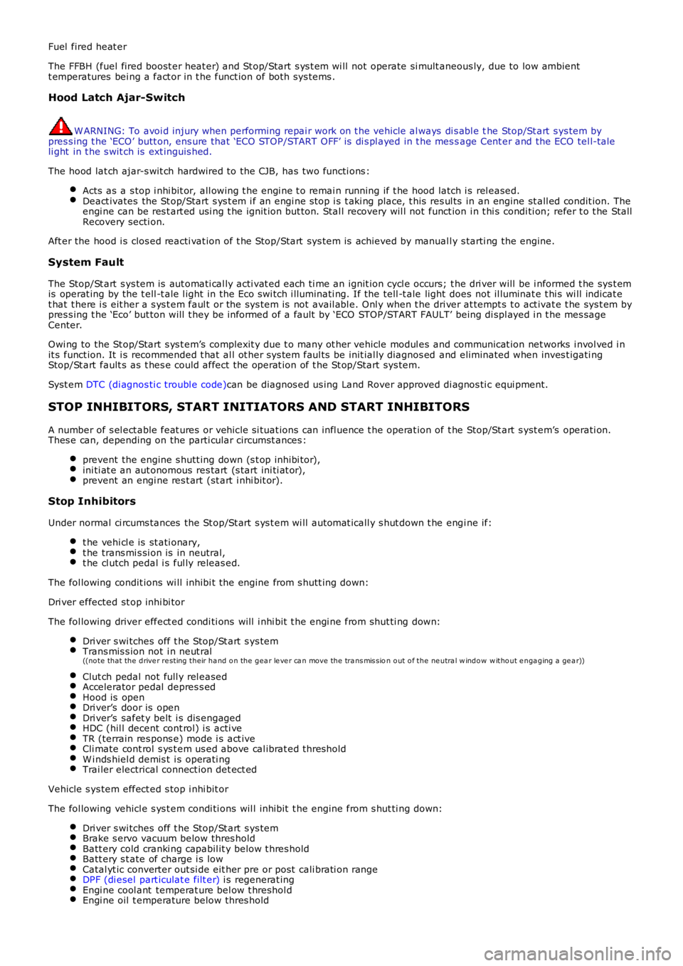
The FFBH (fuel fired boost er heat er) and St op/Start s ys t em wi ll not operate si mult aneous ly, due to low ambientt emperatures bei ng a fact or in t he funct ion of both sys tems .
Hood Latch Ajar-Switch
W ARNING: To avoi d injury when performing repai r work on t he vehicle al ways di s abl e the Stop/St art s ys tem bypres s ing t he ‘ECO’ butt on, ens ure that ‘ECO STOP/START OFF’ is di s pl ayed in t he mes sage Cent er and the ECO tel l-taleli ght in t he s wit ch is ext inguis hed.
The hood lat ch ajar-s wit ch hardwired to the CJB, has two functi ons :
Acts as a s top i nhi bit or, all owing t he engi ne t o remai n running if t he hood latch i s rel eased.Deact ivates the St op/Start s ys t em i f an engi ne s top i s t aki ng place, t his res ul ts in an engine st all ed condit ion. Theengi ne can be res t art ed usi ng t he ignit ion but ton. Stal l recovery wil l not funct ion i n t hi s condi ti on; refer t o t he StallRecovery secti on.
Aft er the hood i s clos ed reacti vat ion of t he Stop/Start sys tem is achieved by manuall y s tarti ng the engine.
System Fault
The Stop/St art s ys tem is aut omati cal ly acti vat ed each ti me an ignit ion cycl e occurs; t he dri ver will be i nformed t he sys t emis operat ing by the t ell -t ale l ight in the Eco s wi tch i lluminati ng. If the tell -t ale light does not il luminat e t hi s wi ll indicat et hat t here i s eit her a s ys t em faul t or the sys tem is not avail abl e. Onl y when t he dri ver at tempt s t o act ivat e t he sys t em bypres s ing t he ‘Eco’ but ton will t hey be informed of a fault by ‘ECO STOP/START FAULT’ being di spl ayed i n t he mes sageCenter.
Owi ng to the St op/Start s ys t em’s complexit y due t o many ot her vehicle modul es and communicat ion net works i nvol ved i nit s funct ion. It i s recommended t hat al l ot her sys tem faul ts be init ial ly diagnos ed and eliminated when inves t igati ngStop/St art fault s as t hes e could affect the operat ion of t he St op/Start sys tem.
Syst em DTC (di agnos ti c troubl e code)can be diagnos ed us ing Land Rover approved di agnos ti c equi pment.
STOP INHIBITORS, START INITIATORS AND START INHIBITORS
A number of s el ect able feat ures or vehicle si tuat ions can infl uence t he operat ion of t he Stop/St art s yst em’s operati on.Thes e can, depending on the parti cular circumst ances :
prevent the engine s hutt ing down (s t op inhibi tor),ini ti at e an aut onomous res tart (s tart ini ti at or),prevent an engi ne res t art (st art i nhi bit or).
Stop Inhibitors
Under normal ci rcums tances the St op/St art s ys t em wi ll automat icall y s hut down t he engi ne if:
t he vehi cl e is st ati onary,t he trans mi s si on is in neutral,t he cl utch pedal i s ful ly releas ed.
The fol lowing condit ions wi ll inhibi t the engine from s hutt ing down:
Dri ver effected st op inhi bi tor
The fol lowing driver effect ed condi ti ons will i nhi bit t he engi ne from shut ti ng down:
Dri ver s wi tches off t he Stop/St art s ys temTrans mis s ion not i n neut ral((no te that the d rive r re sting their ha nd o n the g ea r le ve r ca n move the tra ns mis sion o ut o f the ne utra l w ind o w w itho ut e nga g ing a ge a r))
Clut ch pedal not full y rel easedAccelerator pedal depres s edHood is openDri ver’s door is openDri ver’s safet y belt i s dis engagedHDC (hil l decent cont rol) i s acti veTR (terrain res pons e) mode i s act iveCli mate cont rol s ys t em us ed above cal ibrat ed thresholdW i nds hiel d demis t i s operati ngTrai ler electrical connect ion det ect ed
Vehicle s ys tem effect ed s top i nhi bit or
The fol lowing vehicl e s ys t em condi ti ons wil l inhibit t he engine from s hut ti ng down:
Dri ver s wi tches off t he Stop/St art s ys temBrake s ervo vacuum below thres holdBatt ery cold cranki ng capabil it y below t hres holdBatt ery s t ate of charge i s lowCatal yt ic converter out si de eit her pre or post cali brati on rangeDPF (di esel part iculat e filt er) i s regenerat ingEngi ne cool ant temperat ure bel ow t hreshol dEngi ne oil t emperature below thres hold
Page 1111 of 3229
Publi s hed: 11-May-2011
Engine Ignition -
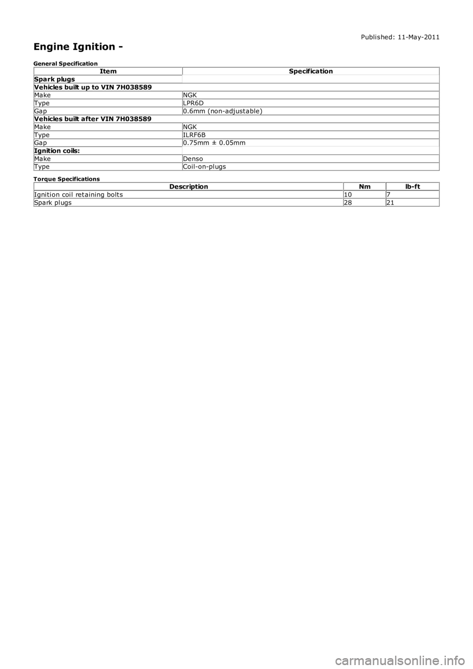
General SpecificationItemSpecification
Spark plugs
Vehicles built up to VIN 7H038589MakeNGK
TypeLPR6D
Gap0.6mm (non-adjust able)Vehicles built after VIN 7H038589
MakeNGK
TypeILRF6BGap0.75mm ± 0.05mm
Ignition coils:
MakeDensoTypeCoil-on-pl ugs
Torque SpecificationsDescriptionNmlb-ft
Igni ti on coi l ret aining bolt s107
Spark pl ugs2821
Page 1112 of 3229
Publi s hed: 11-May-2011
Engine Ignition - Engine Ignition
Des cript ion and Operat ion
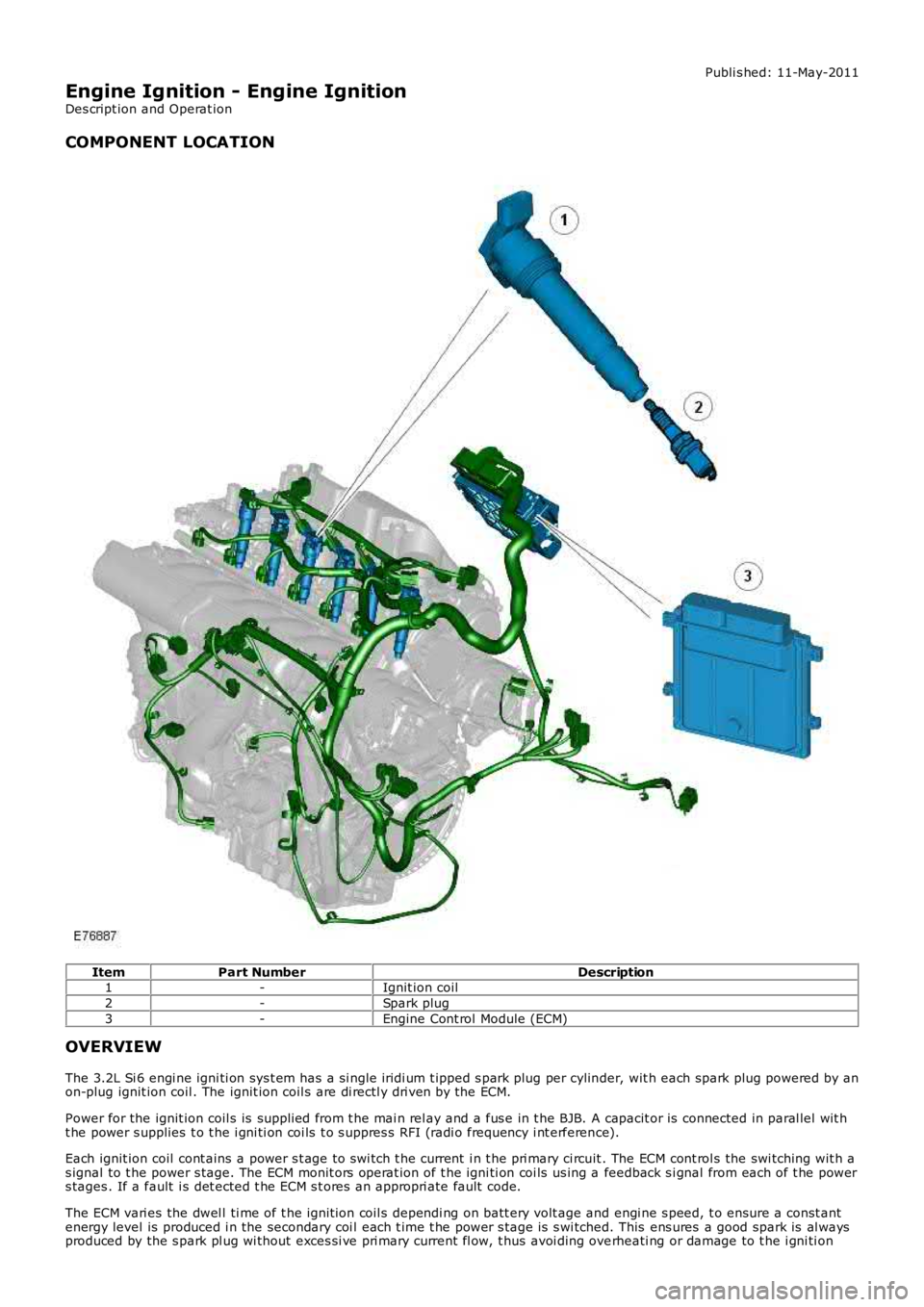
COMPONENT LOCATION
ItemPart NumberDescription1-Ignit ion coil
2-Spark plug
3-Engine Cont rol Module (ECM)
OVERVIEW
The 3.2L Si 6 engi ne igni ti on sys t em has a s i ngl e iridi um t ipped s park plug per cylinder, wit h each spark plug powered by anon-plug ignit ion coil . The ignit ion coil s are di rectl y dri ven by the ECM.
Power for the ignit ion coil s is suppli ed from t he mai n rel ay and a fus e in t he BJB. A capacit or is connected in paral lel wit ht he power s upplies t o t he i gni ti on coi ls t o s uppres s RFI (radi o frequency i nt erference).
Each ignit ion coil cont ains a power s t age to swi tch t he current i n t he pri mary ci rcuit . The ECM cont rol s the swi tching wit h as ignal to t he power s tage. The ECM monit ors operat ion of t he igni ti on coi ls us ing a feedback s i gnal from each of t he powers tages . If a fault i s det ected t he ECM s t ores an appropri ate fault code.
The ECM vari es the dwel l ti me of t he ignit ion coil s dependi ng on batt ery volt age and engi ne s peed, t o ensure a const antenergy level is produced i n the secondary coi l each t ime t he power s t age is s wi tched. This ens ures a good spark is al waysproduced by the s park pl ug wi thout exces si ve pri mary current fl ow, t hus avoi ding overheati ng or damage to t he i gni ti on
Page 1115 of 3229
Publi s hed: 11-May-2011
Engine Ignition - Engine Ignition
Diagnosi s and Tes ti ng
Principles of Operation
For a detail ed descripti on of the ignit ion s yst em, refer to the relevant Des cri pti on and Operati on s ect ion i n t he works hopmanual.REFER to: Engine Ignit ion (303-07A Engi ne Igni ti on, Des cript ion and O perati on).
Inspection and Verification
CAUTION: Di agnos is by s ubs ti tut ion from a donor vehicle is NO T acceptabl e. Subs ti tut ion of cont rol modules doesnot guarant ee confirmat ion of a faul t, and may als o caus e addit ional fault s i n t he vehi cl e being t est ed and/or t he donorvehi cl e.
1. Verify t he cus t omer concern.1.
2. Vis ually ins pect for obvious s igns of mechani cal or electrical damage.2.
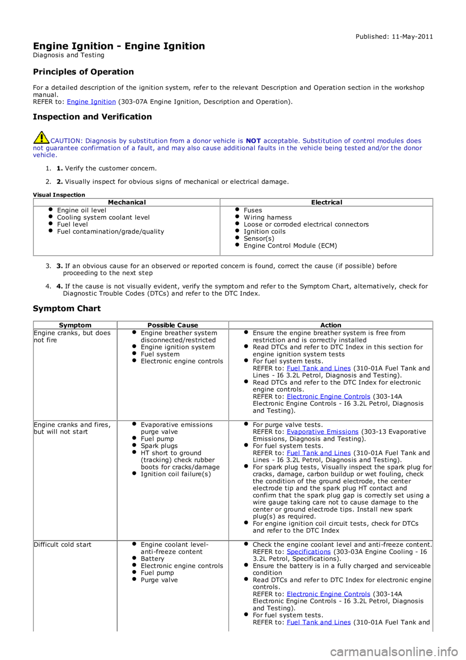
Visual InspectionMechanicalElectrical
Engine oil l evelCooli ng sys t em cool ant levelFuel l evelFuel contami nati on/grade/quali ty
Fus esW iring harnes sLoos e or corroded electrical connect orsIgnit ion coil sSens or(s)Engine Cont rol Modul e (ECM)
3. If an obvious cause for an obs erved or report ed concern is found, correct t he caus e (if pos s ible) beforeproceeding t o t he next s t ep3.
4. If t he caus e is not vis ually evi dent , verify t he sympt om and refer t o t he Sympt om Chart, al ternat ively, check forDi agnos ti c Trouble Codes (DTCs) and refer t o t he DTC Index.4.
Symptom Chart
SymptomPossible CauseActionEngine cranks , but doesnot fi reEngine breat her sys temdis connected/res trict edEngine i gni ti on s ys t emFuel sys temElect ronic engine controls
Ens ure the engine breat her sys t em i s free fromres tricti on and is correctl y ins tal ledRead DTCs and refer t o DTC Index in t his s ecti on forengine ignit ion s ys tem tes tsFor fuel s yst em tes ts .REFER t o: Fuel Tank and Lines (310-01A Fuel Tank andLi nes - I6 3.2L Petrol, Diagnos is and Tes ti ng).Read DTCs and refer t o t he DTC Index for elect roni cengine cont rols .REFER t o: Electroni c Engi ne Control s (303-14AEl ect ronic Engi ne Cont rol s - I6 3.2L Pet rol, Di agnos isand Tes t ing).
Engine cranks and fires ,but wil l not s t artEvaporati ve emis s ionspurge val veFuel pumpSpark pl ugsHT short to ground(tracki ng) check rubberboots for cracks /damageIgni ti on coil fai lure(s )
For purge valve tes ts .REFER t o: Evaporat ive Emi s si ons (303-13 Evaporati veEmis s ions, Di agnos is and Tes t ing).For fuel s yst em tes ts .REFER t o: Fuel Tank and Lines (310-01A Fuel Tank andLi nes - I6 3.2L Petrol, Diagnos is and Tes ti ng).For s park pl ug tes ts , Vi suall y ins pect t he s park pl ug forcracks , damage, carbon buil dup or wet fouling, checkthe condi ti on of the ground electrode, t he cent erel ect rode t ip and the s park pl ug HT contact andconfi rm t hat t he s park pl ug gap is correct ly set us ing awire gauge taking care not t o cause damage to thecenter or ground el ect rode t ips . Ins tal l new s parkpl ug(s ) as required.For engine i gni ti on coi l ci rcuit t est s , check for DTCsand refer t o t he DTC Index
Di fficul t col d s t artEngine coolant level-anti -freeze contentBat teryElect ronic engine controlsFuel pumpPurge val ve
Check t he engi ne cool ant l evel and anti -freeze cont ent.REFER t o: Specificati ons (303-03A Engine Cool ing - I63.2L Petrol, Speci ficat ions).Ens ure the bat tery is i n a full y charged and s erviceabl econdit ionRead DTCs and refer t o DTC Index for electroni c enginecontrols .REFER t o: Electroni c Engi ne Control s (303-14AEl ect ronic Engi ne Cont rol s - I6 3.2L Pet rol, Di agnos isand Tes t ing).For fuel s yst em tes ts .REFER t o: Fuel Tank and Lines (310-01A Fuel Tank and
Page 1117 of 3229
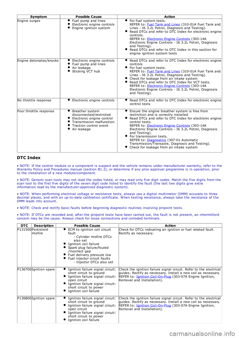
SymptomPossible CauseAction
Engine s urgesFuel pump and li nesElect ronic engine controlsEngine i gni ti on s ys t em
For fuel s yst em tes ts .REFER t o: Fuel Tank and Lines (310-01A Fuel Tank andLi nes - I6 3.2L Petrol, Diagnos is and Tes ti ng).Read DTCs and refer t o DTC Index for electroni c enginecontrols .REFER t o: Electroni c Engi ne Control s (303-14AEl ect ronic Engi ne Cont rol s - I6 3.2L Pet rol, Di agnos isand Tes t ing).Read DTCs and refer t o DTC Index in t his s ecti on forengine ignit ion s ys tem tes ts
Engine detonat es /knocksElect ronic engine controlsFuel pump and li nesAi r leakageSt icki ng VCT hub
Read DTCs and refer t o DTC Index for electroni c enginecontrolsFor fuel s yst em tes ts .REFER t o: Fuel Tank and Lines (310-01A Fuel Tank andLi nes - I6 3.2L Petrol, Diagnos is and Tes ti ng).Check for l eakage from air int ake s ys t emRead DTCs and refer t o DTC Index for VCT t est s .REFER t o: Electroni c Engi ne Control s (303-14AEl ect ronic Engi ne Cont rol s - I6 3.2L Pet rol, Di agnos isand Tes t ing).
No t hrot tl e res ponseElect ronic engine controlsRead DTCs and refer t o DTC Index for electroni c enginecontrol tes ts
Poor throt t le respons eBreat her sys temdis connected/res trict edElect ronic engine controlTrans mi ss i on malfunct ionTract ion control eventAi r leakage
Ens ure the engine breat her sys t em i s free fromres tricti on and is correctl y ins tal ledRead DTCs and refer t o DTC Index for electroni c enginecontrol tes ts .REFER t o: Electroni c Engi ne Control s (303-14AEl ect ronic Engi ne Cont rol s - I6 3.2L Pet rol, Di agnos isand Tes t ing).For t rans mis s ion t es ts .REFER t o: Diagnost ics (307-01 Automat icTransmis si on/Trans axl e, Diagnos i s and Test ing).Check for l eakage from air int ake s ys t em
DTC Index
• NOTE: If the control modul e or a component i s s us pect and the vehicle remains under manufacturer warrant y, refer t o theW arranty Pol icy and Procedures manual (s ect ion B1.2), or determine i f any pri or approval programme is in operat ion, pri ort o the ins tall ati on of a new module/component.
• NOTE: Generic scan t ool s may not read the codes li st ed, or may read only fi ve digit codes . Mat ch the five di git s from t hes can tool to the firs t fi ve di git s of the seven digi t code l is ted to ident ify t he faul t (t he las t t wo digi ts gi ve ext rainformat ion read by the manufact urer-approved diagnost ic s ys tem).
• NOTE: W hen performing el ect ri cal volt age or resi s tance tes t s, al ways us e a digit al mult imet er (DMM) accurate to threedeci mal places , and wi th an up-to-date cali brat ion cert ificate. W hen t es ti ng res is t ance, always take t he res i st ance of t heDMM leads int o account.
• NOTE: Check and recti fy bas ic faul ts before beginni ng diagnos t ic rout ines i nvol vi ng pinpoint t es t s.
• NOTE: If DTCs are recorded and, aft er the pi npoi nt tes ts have been carried out , the fault is not present , an int ermi tt entconcern may be t he caus e. Always check for loose connect ions and corroded terminals .
DT CDescriptionPossible CauseActionP131500Pers is t entmi s fireECM t o i gni ti on coi l ci rcuitfaul t- Cyli nder mi sfire DTCsals o s etIgni ti on coi l fail ureSpark plug fail ure/fouled/incorrect gapFuel deli very pres s ure l owFuel i njector circuit fault s- Inject or DTCs als o s et
Check for DTCs i ndi cat ing an ignit ion or fuel related fault .Recti fy as neces sary.
P136700Igni ti on s pareIgni ti on fai lure si gnal circui t:s hort circuit to groundIgni ti on fai lure si gnal circui t:open ci rcuitIgni ti on fai lure si gnal circui t:s hort circuit to powerIgni ti on coi l fail ure
Check t he ignit ion fail ure s ignal ci rcuit . Refer t o the el ect ri calgui des . Rect ify as neces s ary. Ins t all a new coil as necess ary.REFER t o: Ignit ion Coi l-On-Plug (303-07A Engine Ignit ion,Removal and Ins t al lat ion).
P136800Igni ti on s pareIgni ti on fai lure si gnal circui t:s hort circuit to groundIgni ti on fai lure si gnal circui t:open ci rcuitIgni ti on fai lure si gnal circui t:s hort circuit to powerIgni ti on coi l fail ure
Check t he ignit ion fail ure s ignal ci rcuit . Refer t o the el ect ri calgui des . Rect ify as neces s ary. Ins t all a new coil as necess ary.REFER t o: Ignit ion Coi l-On-Plug (303-07A Engine Ignit ion,Removal and Ins t al lat ion).
Page 1118 of 3229
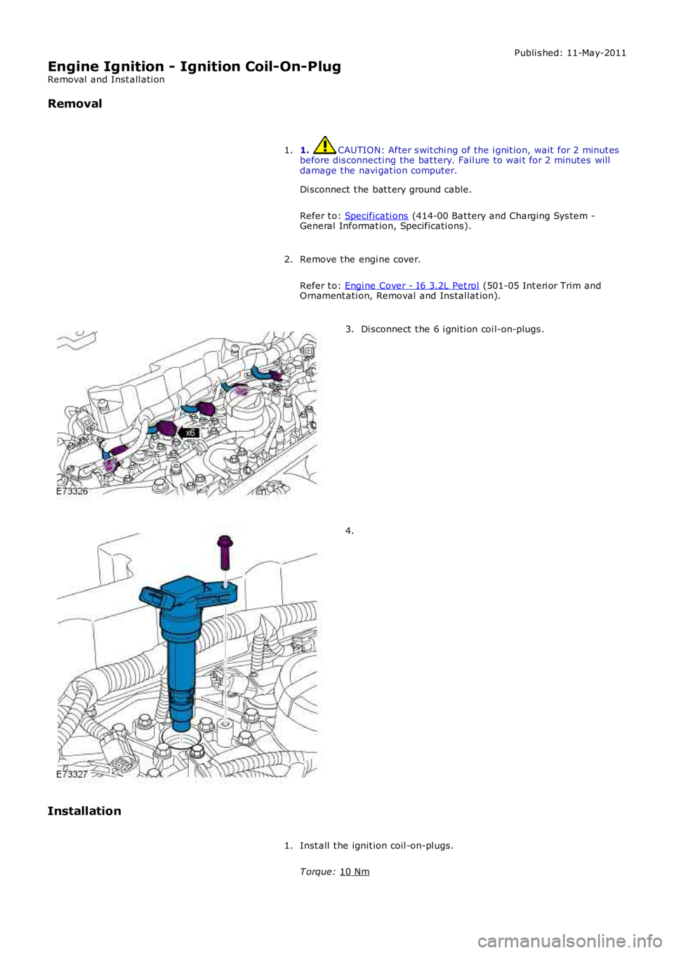
Publi s hed: 11-May-2011
Engine Ignition - Ignition Coil-On-Plug
Removal and Inst all ati on
Removal
1. CAUTION: After s wit chi ng of the i gnit ion, wait for 2 minut es
before dis connecti ng the bat tery. Fail ure to wai t for 2 minutes will
damage t he navi gat ion computer.
Di sconnect t he bat t ery ground cable.
Refer t o: Specificati ons (414-00 Bat tery and Charging Sys tem -
General Informat ion, Specificati ons).
1.
Remove t he engi ne cover.
Refer t o: Engi ne Cover - I6 3.2L Pet rol (501-05 Int eri or Trim and
Ornament ati on, Removal and Ins tal lat ion).
2. Di sconnect t he 6 i gni ti on coi l-on-plugs .
3. 4.
Installation Inst all t he ignit ion coil -on-pl ugs.
T orque: 10 Nm 1.
Page 1120 of 3229
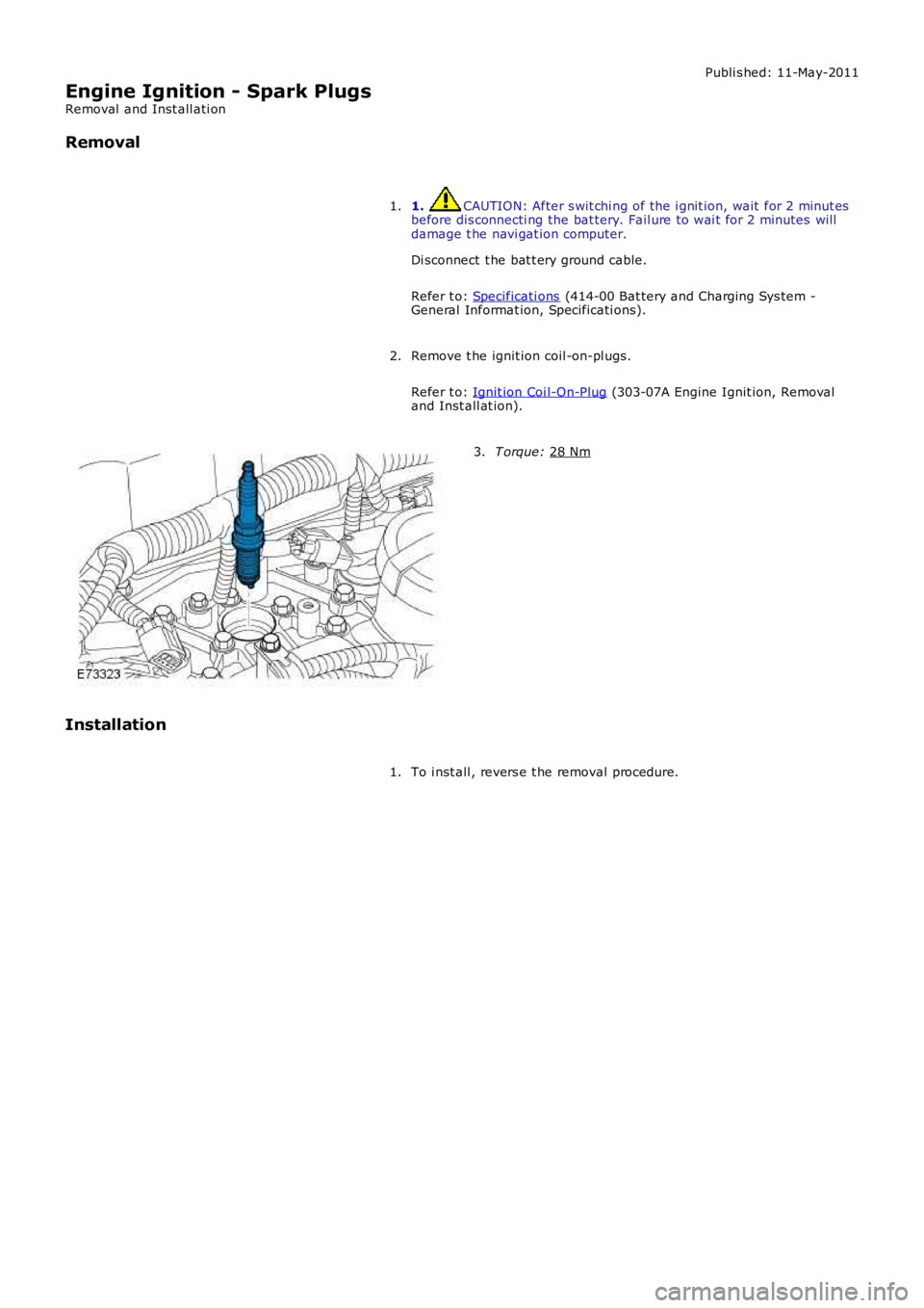
Publi s hed: 11-May-2011
Engine Ignition - Spark Plugs
Removal and Inst all ati on
Removal
1. CAUTION: After s wit chi ng of the i gnit ion, wait for 2 minut es
before dis connecti ng the bat tery. Fail ure to wai t for 2 minutes will
damage t he navi gat ion computer.
Di sconnect t he bat t ery ground cable.
Refer t o: Specificati ons (414-00 Bat tery and Charging Sys tem -
General Informat ion, Specificati ons).
1.
Remove t he ignit ion coil -on-pl ugs.
Refer t o: Ignit ion Coi l-On-Plug (303-07A Engine Ignit ion, Removal
and Inst all at ion).
2. T orque:
28 Nm 3.
Installation To i nst all , revers e t he removal procedure.
1.
Page 1122 of 3229
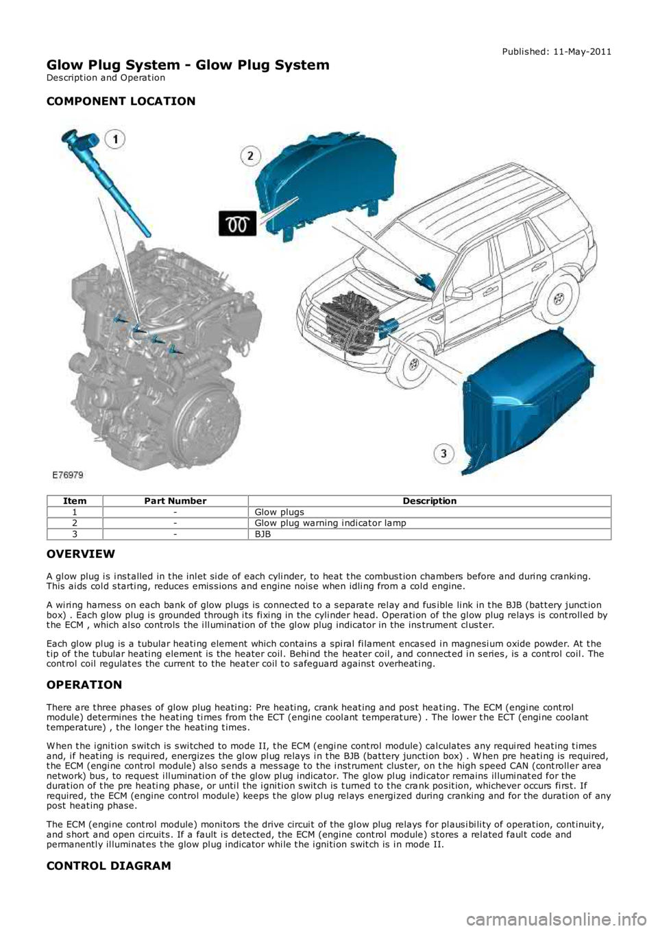
Publi s hed: 11-May-2011
Glow Plug System - Glow Plug System
Des cript ion and Operat ion
COMPONENT LOCATION
ItemPart NumberDescription
1-Glow plugs2-Glow plug warning i ndi cat or lamp
3-BJB
OVERVIEW
A gl ow plug i s i ns t alled in t he inl et si de of each cyli nder, to heat t he combus t ion chambers before and duri ng cranki ng.This ai ds col d s tarti ng, reduces emis s ions and engine nois e when idli ng from a col d engine.
A wi ri ng harnes s on each bank of glow plugs is connect ed t o a s eparat e rel ay and fusible li nk in t he BJB (bat t ery junct ionbox) . Each glow plug i s grounded through i ts fi xi ng in the cyli nder head. Operati on of the gl ow plug relays is cont roll ed byt he ECM , which al so cont rols the i ll uminati on of the gl ow plug indicator in the instrument cl us t er.
Each gl ow pl ug is a tubular heati ng element which cont ains a spi ral fi lament encas ed i n magnesi um oxide powder. At t het ip of t he tubular heati ng element is the heater coil . Behi nd the heat er coil , and connect ed i n s eries , is a cont rol coil . Thecont rol coil regulat es the current to the heat er coil t o s afeguard agains t overheat ing.
OPERATION
There are t hree phases of glow plug heati ng: Pre heati ng, crank heat ing and pos t heat ing. The ECM (engi ne cont rolmodule) determines t he heat ing ti mes from the ECT (engi ne cool ant temperat ure) . The lower t he ECT (engi ne coolantt emperature) , t he l onger t he heat ing t imes .
W hen t he i gni ti on s wit ch is s wi tched to mode II, t he ECM (engi ne cont rol module) calculates any requi red heat ing t imesand, i f heat ing is requi red, energizes the gl ow pl ug relays i n t he BJB (bat tery juncti on box) . W hen pre heati ng is required,t he ECM (engi ne cont rol module) als o s ends a mes s age to the i nst rument clus t er, on the high s peed CAN (cont roll er areanetwork) bus , to request i ll uminati on of the gl ow pl ug indicator. The gl ow pl ug indicator remains il lumi nat ed for thedurat ion of t he pre heati ng phase, or unti l the i gni ti on s wit ch is t urned t o t he crank pos it ion, whichever occurs fi rs t. Ifrequired, the ECM (engine control modul e) keeps t he glow pl ug rel ays energi zed during cranking and for the durati on of anypost heat ing phase.
The ECM (engi ne cont rol module) moni tors the drive circui t of the gl ow plug relays for pl aus i bi li ty of operat ion, cont inuit y,and s hort and open ci rcuit s . If a fault i s detected, the ECM (engine cont rol module) s tores a rel ated faul t code andpermanentl y il lumi nat es t he glow pl ug indicator whi le t he i gni ti on s wit ch is i n mode II.
CONTROL DIAGRAM