2006 LAND ROVER FRELANDER 2 engine oil
[x] Cancel search: engine oilPage 752 of 3229
Publi s hed: 11-May-2011
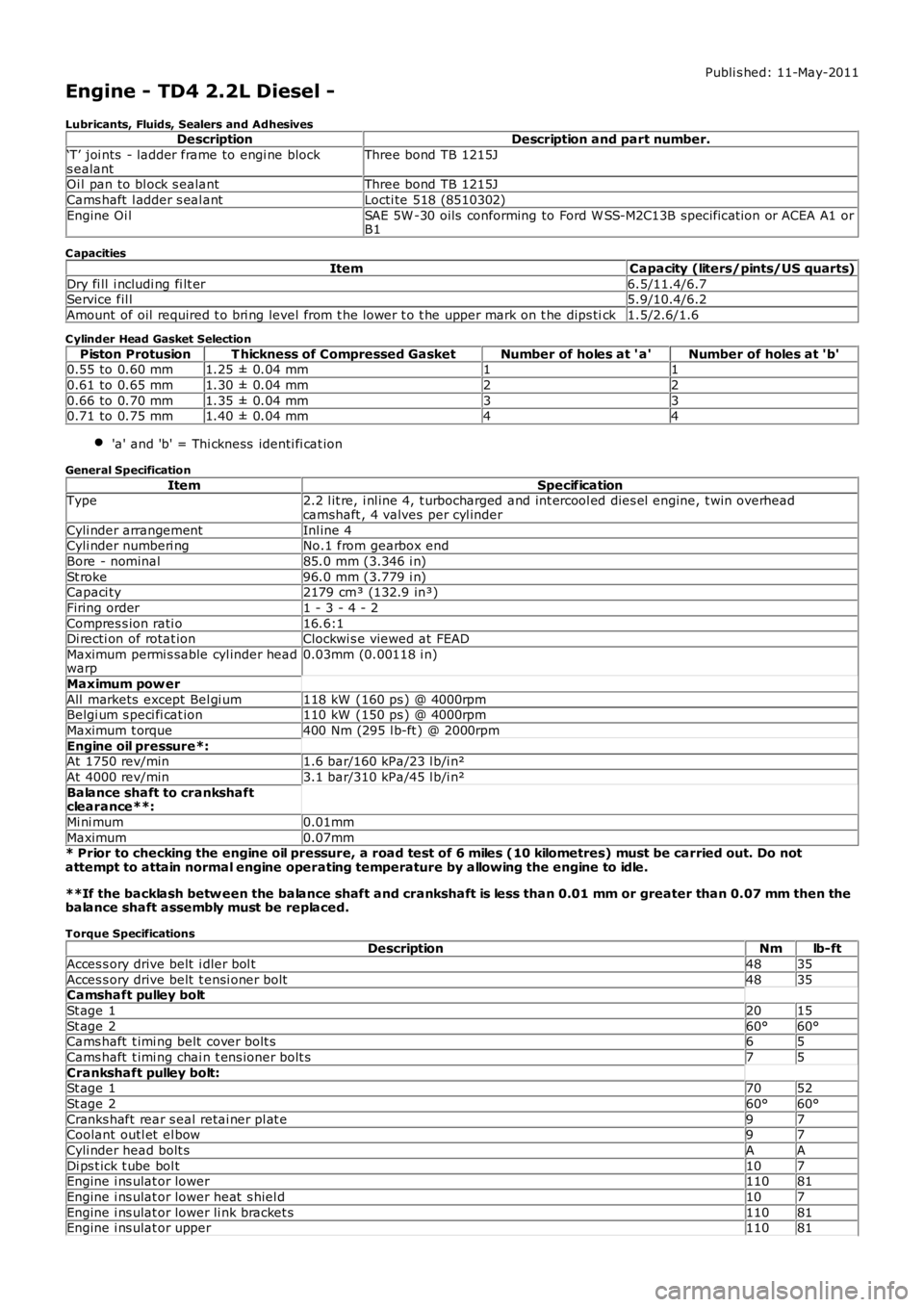
Engine - TD4 2.2L Diesel -
Lubricants, Fluids, Sealers and AdhesivesDescriptionDescription and part number.
‘T’ joi nts - ladder frame to engi ne blocks ealantThree bond TB 1215J
Oi l pan to bl ock s ealantThree bond TB 1215J
Cams haft l adder s eal antLocti te 518 (8510302)
Engine Oi lSAE 5W -30 oils conforming to Ford W SS-M2C13B specificat ion or ACEA A1 orB1
C apacities
ItemCapacity (liters/pints/US quarts)
Dry fi ll i ncludi ng fi lt er6.5/11.4/6.7Service fil l5.9/10.4/6.2
Amount of oil required t o bri ng level from t he lower t o t he upper mark on t he dips tick1.5/2.6/1.6
C ylinder Head Gasket Selection
Piston ProtusionT hickness of Compressed GasketNumber of holes at ' a'Number of holes at 'b'0.55 to 0.60 mm1.25 ± 0.04 mm11
0.61 to 0.65 mm1.30 ± 0.04 mm22
0.66 to 0.70 mm1.35 ± 0.04 mm330.71 to 0.75 mm1.40 ± 0.04 mm44
'a' and 'b' = Thi ckness identi fi cat ion
General Specification
ItemSpecificationType2.2 l it re, i nl ine 4, t urbocharged and int ercool ed dies el engine, t win overheadcamshaft , 4 valves per cyl inder
Cyli nder arrangementInl ine 4Cyli nder numberi ngNo.1 from gearbox end
Bore - nominal85.0 mm (3.346 i n)
St roke96.0 mm (3.779 i n)Capaci ty2179 cm³ (132.9 in³)
Firing order1 - 3 - 4 - 2
Compres s ion rati o16.6:1Di recti on of rotat ionClockwi s e viewed at FEAD
Maximum permi s sable cyl inder headwarp0.03mm (0.00118 i n)
Maximum pow er
All markets except Bel gi um118 kW (160 ps ) @ 4000rpmBelgi um s peci fi cat ion110 kW (150 ps ) @ 4000rpm
Maximum t orque400 Nm (295 l b-ft ) @ 2000rpm
Engine oil pressure*:At 1750 rev/min1.6 bar/160 kPa/23 l b/i n²
At 4000 rev/min3.1 bar/310 kPa/45 l b/i n²
Balance shaft to crankshaftclearance**:
Mi ni mum0.01mm
Maximum0.07mm* Prior to checking the engine oil pressure, a road test of 6 miles (10 kilometres) must be carried out. Do notattempt to attain normal engine operating temperature by allowing the engine to idle.
**If the backlash betw een the balance shaft and crankshaft is less than 0.01 mm or greater than 0.07 mm then thebalance shaft assembly must be replaced.
Torque SpecificationsDescriptionNmlb-ft
Acces s ory drive belt i dler bol t4835
Acces s ory drive belt t ensi oner bolt4835Camshaft pulley bolt
St age 12015
St age 260°60°Cams haft t imi ng belt cover bolt s65
Cams haft t imi ng chai n t ens ioner bolt s75
Crankshaft pulley bolt:St age 17052
St age 260°60°
Cranks haft rear s eal retai ner pl at e97Coolant outl et el bow97
Cyli nder head bolt sAA
Di ps t ick t ube bol t107Engine i ns ulat or lower11081
Engine i ns ulat or lower heat s hiel d107
Engine i ns ulat or lower li nk bracket s11081Engine i ns ulat or upper11081
Page 753 of 3229
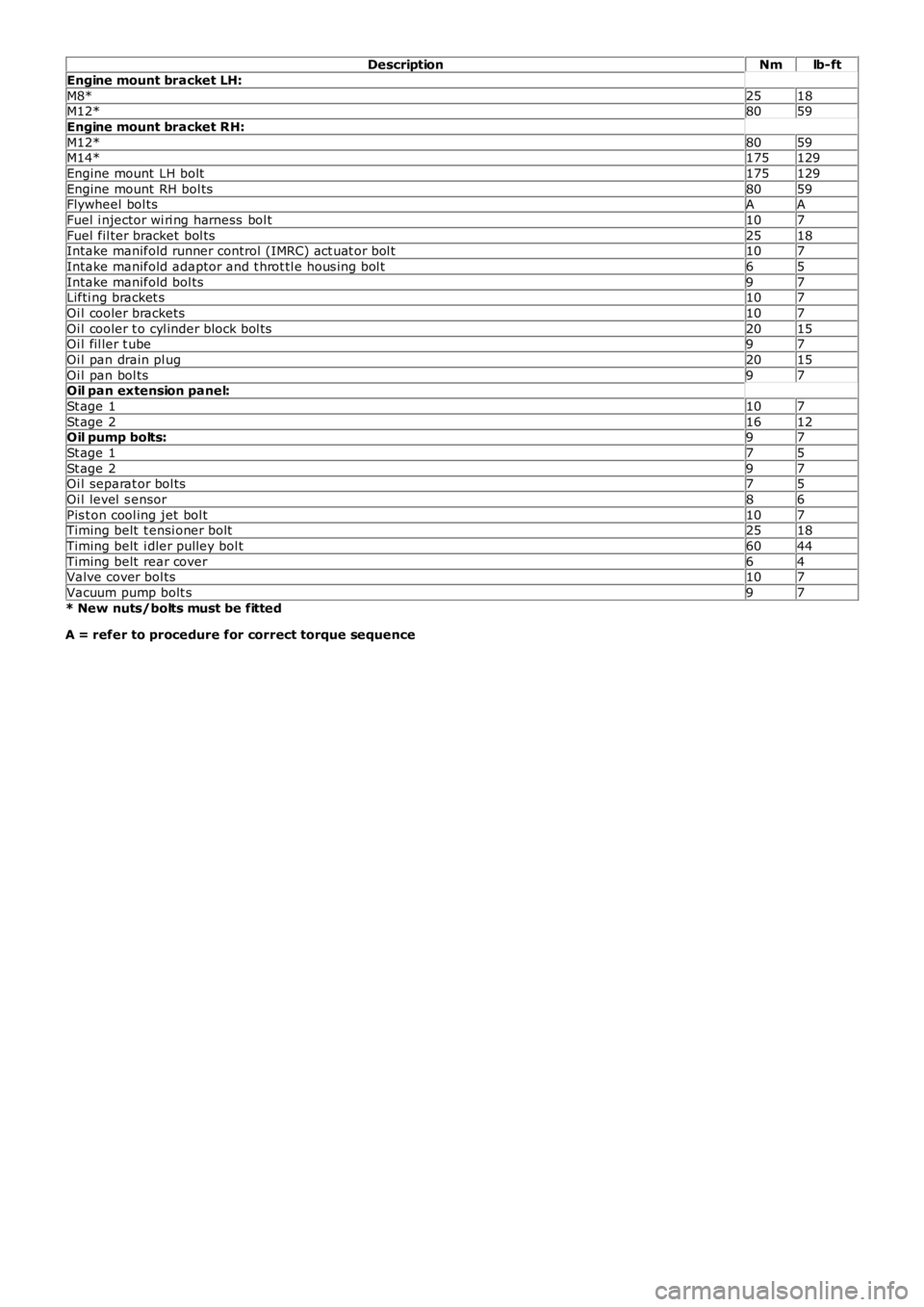
DescriptionNmlb-ft
Engine mount bracket LH:
M8*2518M12*8059
Engine mount bracket RH:
M12*8059M14*175129
Engine mount LH bolt175129
Engine mount RH bol ts8059Flywheel bol tsAA
Fuel i njector wi ri ng harness bol t107
Fuel fil ter bracket bol ts2518Intake manifold runner control (IMRC) act uat or bol t107
Intake manifold adaptor and t hrot tl e hous i ng bol t65
Intake manifold bol ts97Lifti ng bracket s107
Oi l cooler brackets107
Oi l cooler t o cyl inder block bol ts2015Oi l fil ler t ube97
Oi l pan drain pl ug2015
Oi l pan bol ts97Oil pan extension panel:
St age 1107
St age 21612Oil pump bolts:97
St age 175
St age 297Oi l separat or bol ts75
Oi l level s ensor86
Pis t on cool ing jet bol t107Timing belt t ensi oner bolt2518
Timing belt i dler pulley bol t6044
Timing belt rear cover64Valve cover bol ts107
Vacuum pump bolt s97
* New nuts/bolts must be fitted
A = refer to procedure for correct torque sequence
Page 755 of 3229
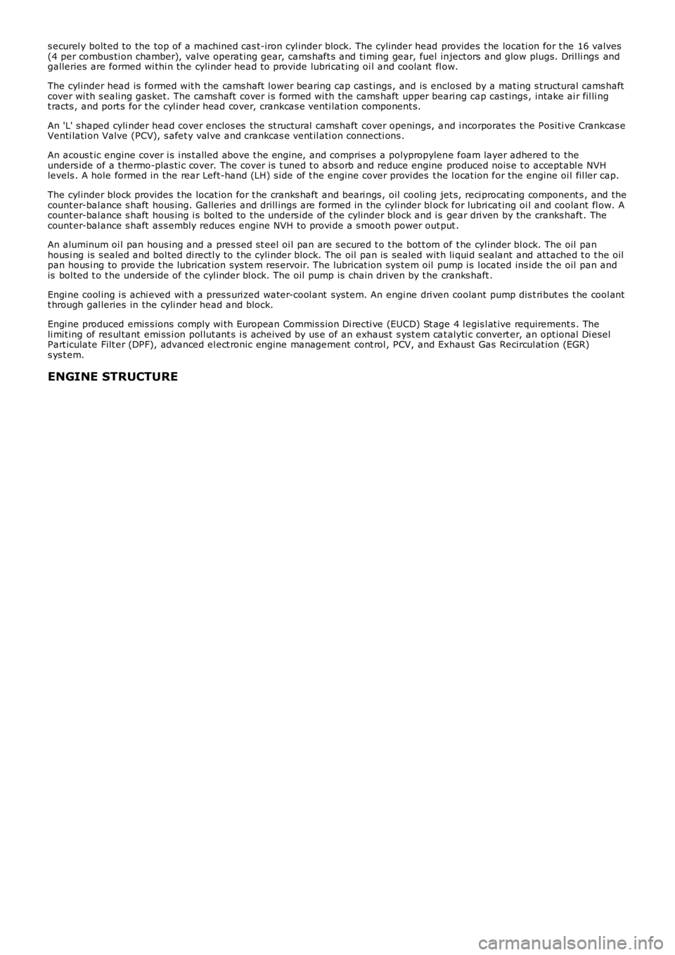
s ecurel y bolt ed to the top of a machined cas t-iron cyl inder block. The cylinder head provides t he locati on for t he 16 valves(4 per combus ti on chamber), valve operat ing gear, cams haft s and ti ming gear, fuel inject ors and glow plugs. Dril li ngs andgalleries are formed wi thi n the cyli nder head t o provide lubri cat ing oi l and coolant fl ow.
The cyl inder head is formed wit h the cams haft l ower bearing cap cas t ings , and is enclos ed by a mat ing s t ructural cams haftcover wi th s eali ng gasket. The cams haft cover i s formed wi th the cams haft upper beari ng cap cas t ings , intake ai r fil li ngt racts , and port s for t he cyl inder head cover, crankcas e venti lat ion component s.
An 'L' s haped cyli nder head cover enclos es the s t ructural cams haft cover openings, and i ncorporates t he Posi ti ve Crankcas eVenti lati on Valve (PCV), s afet y val ve and crankcas e vent il ati on connecti ons .
An acous t ic engine cover i s i ns t alled above t he engi ne, and compris es a polypropylene foam layer adhered to theunders ide of a t hermo-plas ti c cover. The cover i s t uned t o abs orb and reduce engine produced nois e t o accept abl e NVHlevels . A hole formed in the rear Left-hand (LH) s ide of t he engine cover provi des the l ocat ion for the engine oi l fil ler cap.
The cyl inder block provides t he locat ion for t he cranks haft and beari ngs , oil cooling jet s, reci procat ing component s , and thecount er-bal ance s haft hous ing. Galleries and drill ings are formed in the cyli nder block for lubri cat ing oi l and coolant fl ow. Acount er-bal ance s haft hous ing i s bolt ed to the unders ide of t he cylinder block and is gear dri ven by the cranks haft . Thecount er-bal ance s haft as s embly reduces engine NVH to provi de a s moot h power out put .
An aluminum oi l pan hous ing and a pres sed st eel oi l pan are s ecured t o t he bot t om of t he cyl inder bl ock. The oil panhous i ng is s ealed and bol ted di rectl y to the cyli nder block. The oil pan is sealed wit h li qui d s ealant and att ached t o t he oilpan hous i ng to provide t he lubricat ion sys tem res ervoir. The lubricat ion sys tem oil pump i s l ocated ins ide t he oil pan andis bol ted t o t he unders ide of t he cyl inder bl ock. The oil pump is chain driven by t he cranks haft .
Engi ne cool ing i s achi eved wit h a pres s uri zed water-cool ant sys tem. An engi ne dri ven coolant pump dis t ri but es t he cool antt hrough gal leries in the cyli nder head and block.
Engi ne produced emis s ions comply wi th European Commis s ion Di recti ve (EUCD) St age 4 legis l at ive requirement s . Theli mit ing of res ul tant emi ss i on pol lut ant s i s acheived by us e of an exhaus t s yst em cat alyti c convert er, an opt ional Di eselPart iculate Filt er (DPF), advanced el ect ronic engine management cont rol , PCV, and Exhaus t Gas Recircul at ion (EGR)s ys t em.
ENGINE STRUCTURE
Page 758 of 3229
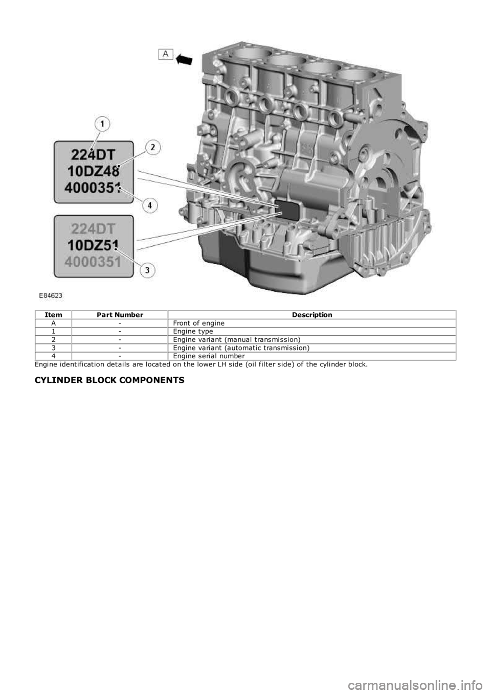
ItemPart NumberDescription
A-Front of engine1-Engine t ype
2-Engine vari ant (manual trans mi s si on)
3-Engine vari ant (automat ic trans mi ss i on)4-Engine s eri al number
Engi ne ident ifi cat ion det ails are l ocat ed on t he lower LH s ide (oil fil ter s ide) of the cyli nder bl ock.
CYLINDER BLOCK COMPONENTS
Page 762 of 3229
11-VGT oil return port
12-VGT oil s uppl y port
The cyl inder block is manufact ured from cas t -i ron and feat ures double layer wal ls t hat provide high st rengt h and ri gidit y.An air cus hion i s formed between t he l ayers and als o acts t o reduce t he NVH l evel s produced by the engine. The blockfeat ures 5 bol ted mai n beari ng journals that als o provi de high s t rength and rigi dit y to the l ower end of t he engine.
The cyl inders are direct ly bored int o t he cyl inder bl ock and do not require cyl inder liners. Two gui de s leeves are l ocated int he cyl inder bl ock, and provided t o correct ly al ign t he cyl inder head and gas ket to the cyli nder block.
A hole formed in the LH rear of the cyli nder bl ock below the st art er motor, provides the locat ion for an engine t imi ngs pecial t ool . W hen i nserted, the special tool locates i n a corres ponding hol e in the flywheel to temporaril y hol d t hecrankshaft wit h No. 1 pis t on at the Top Dead Cent er (TDC) posi ti on.
The oil filt er and cool er hous ing, and main oi l gal lery are locat ed on t he LH s ide of t he cylinder block. The mai n oil gall eryis a longit udinal dril li ng that runs t he l engt h of the cyli nder bl ock, and s uppl ies pres s urized oi l to al l the engine movi ngcomponents . Pres s uri zed oi l is di verted from t he main oi l gal lery to s upply the main and bi g-end bearings via diagonal oildri ll ings in the cyli nder block, and in t he crankshaft journals . The mai n oil gall ery i s s eal ed at each end wit h a s crewedplug.
A cros s dril ling above No. 2 mai n beari ng direct s pres surized oil from the main oi l gal lery to a port at t he Right-Hand (RH)s ide of t he cyl inder bl ock. The port s upplies press urized oil via a banjo t ype connect ion to t he VGT beari ngs. Ret urn oi lfrom the VGT is direct ed via a pipe and a connect ion at the RH si de of the bl ock, i nt o t he oil pan. A vert ical dril li ng at theLH front of the cyli nder bl ock s upplies press uri zed oil from the mai n oil gall ery, up t o a corresponding oi l gal lery in t hecyl inder head.
Engi ne cool ing i s achi eved wit h int er-cyl inder coolant chambers and expans ion chamber dril li ngs , formed i n t he cyl inderblock cool ant jacket . The coolant chambers direct coolant t hrough openings i n t he block upper s urface to the cyli nder head.Core pl ugs seal t he ext eri or openings formed i n t he cyl inder block coolant jacket.
Oil Spray Jets
Page 763 of 3229
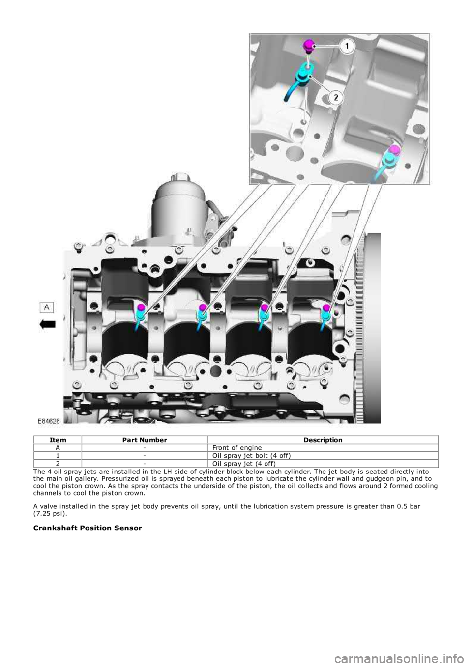
ItemPart NumberDescription
A-Front of engine1-Oil s pray jet bol t (4 off)
2-Oil s pray jet (4 off)
The 4 oi l s pray jet s are i nst all ed in the LH si de of cyl inder bl ock bel ow each cyl inder. The jet body i s s eat ed direct ly i ntot he main oi l gal lery. Pres s uri zed oi l is s prayed beneat h each pis t on to lubri cat e t he cyl inder wall and gudgeon pin, and t ocool t he pis t on crown. As the spray cont act s t he undersi de of the pi st on, the oi l col lect s and flows around 2 formed cool ingchannels t o cool the pi st on crown.
A valve i nst all ed in the s pray jet body prevent s oil s pray, unti l the l ubricati on s ys t em press ure is great er than 0.5 bar(7.25 ps i).
Crankshaft Position Sensor
Page 766 of 3229
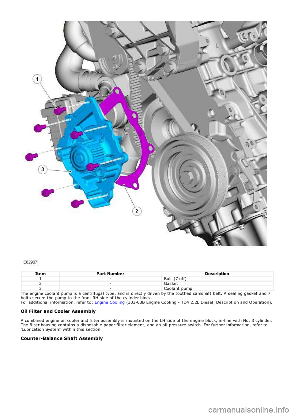
ItemPart NumberDescription
1-Bolt (7 off)2-Gas ket
3-Coolant pump
The engi ne cool ant pump is a cent ri fugal type, and is direct ly driven by t he t oot hed cams haft bel t. A s eal ing gas ket and 7bolt s s ecure the pump to the front RH si de of the cyli nder bl ock.For addit ional informat ion, refer t o: Engi ne Cooling (303-03B Engine Cooli ng - TD4 2.2L Dies el , Descripti on and Operat ion).
Oil Filter and Cooler Assembly
A combined engine oi l cooler and fil ter as sembl y is mount ed on t he LH s ide of t he engine block, in-line wit h No. 3 cylinder.The fi lt er hous ing contai ns a dis pos abl e paper fil ter element , and an oil pres s ure swi tch. For furt her i nformat ion, refer to'Lubri cat ion Sys tem' wi thin thi s s ect ion.
Counter-Balance Shaft Assembly
Page 768 of 3229
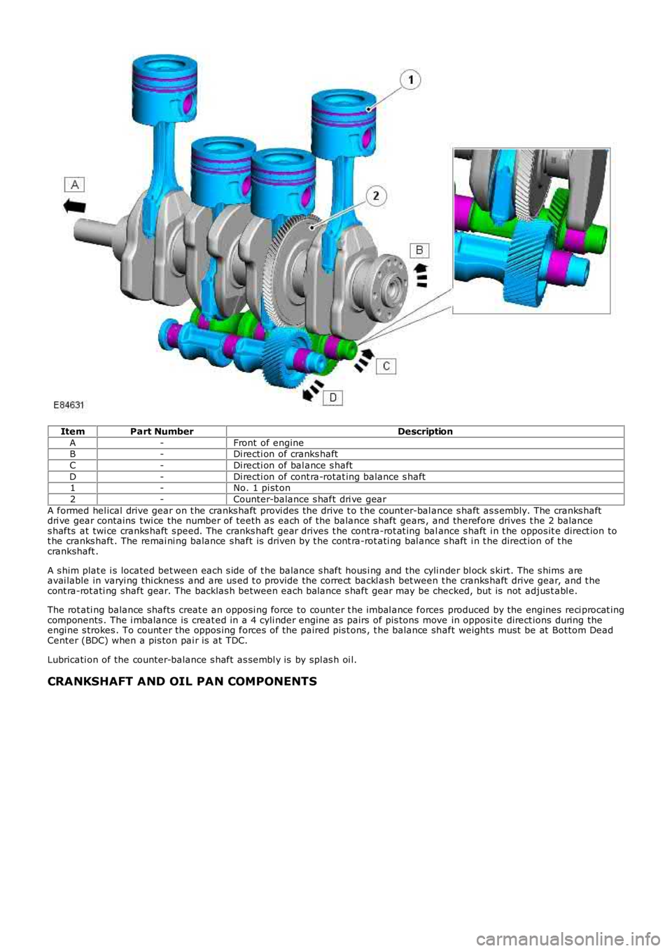
ItemPart NumberDescription
A-Front of engineB-Di recti on of cranks haft
C-Di recti on of bal ance s haft
D-Di recti on of cont ra-rotat ing balance s haft1-No. 1 pi st on
2-Counter-balance s haft dri ve gear
A formed hel ical drive gear on t he cranks haft provi des the drive t o t he count er-bal ance s haft as s embly. The cranks haftdri ve gear contains twi ce the number of teet h as each of the balance s haft gears , and therefore drives t he 2 balances hafts at twi ce cranks haft s peed. The cranks haft gear drives t he cont ra-rot at ing balance s haft i n t he oppos it e direct ion tot he cranks haft . The remai ni ng balance s haft is driven by t he cont ra-rot ati ng bal ance s haft i n t he direct ion of t hecrankshaft .
A s him plat e i s located bet ween each s ide of t he balance s haft hous i ng and the cyli nder bl ock s kirt. The s hims areavai lable in varyi ng thi ckness and are us ed t o provide the correct backl ash bet ween t he cranks haft drive gear, and t hecont ra-rot ati ng shaft gear. The backlas h between each balance s haft gear may be checked, but is not adjus t abl e.
The rot ati ng balance shafts creat e an opposi ng force to counter t he imbal ance forces produced by the engines reci procat ingcomponents . The i mbalance is creat ed in a 4 cyli nder engine as pairs of pis tons move in opposi te direct ions during theengi ne s trokes . To count er the oppos ing forces of the paired pis t ons , t he balance shaft weights must be at Bot tom DeadCenter (BDC) when a pis ton pai r is at TDC.
Lubricati on of the counter-balance s haft as sembl y is by spl as h oi l.
CRANKSHAFT AND OIL PAN COMPONENTS