Page 606 of 3229
Cont rol Module (ECM) cont rols t he fuel injection s ys t em and t he ignit ion s yst em.
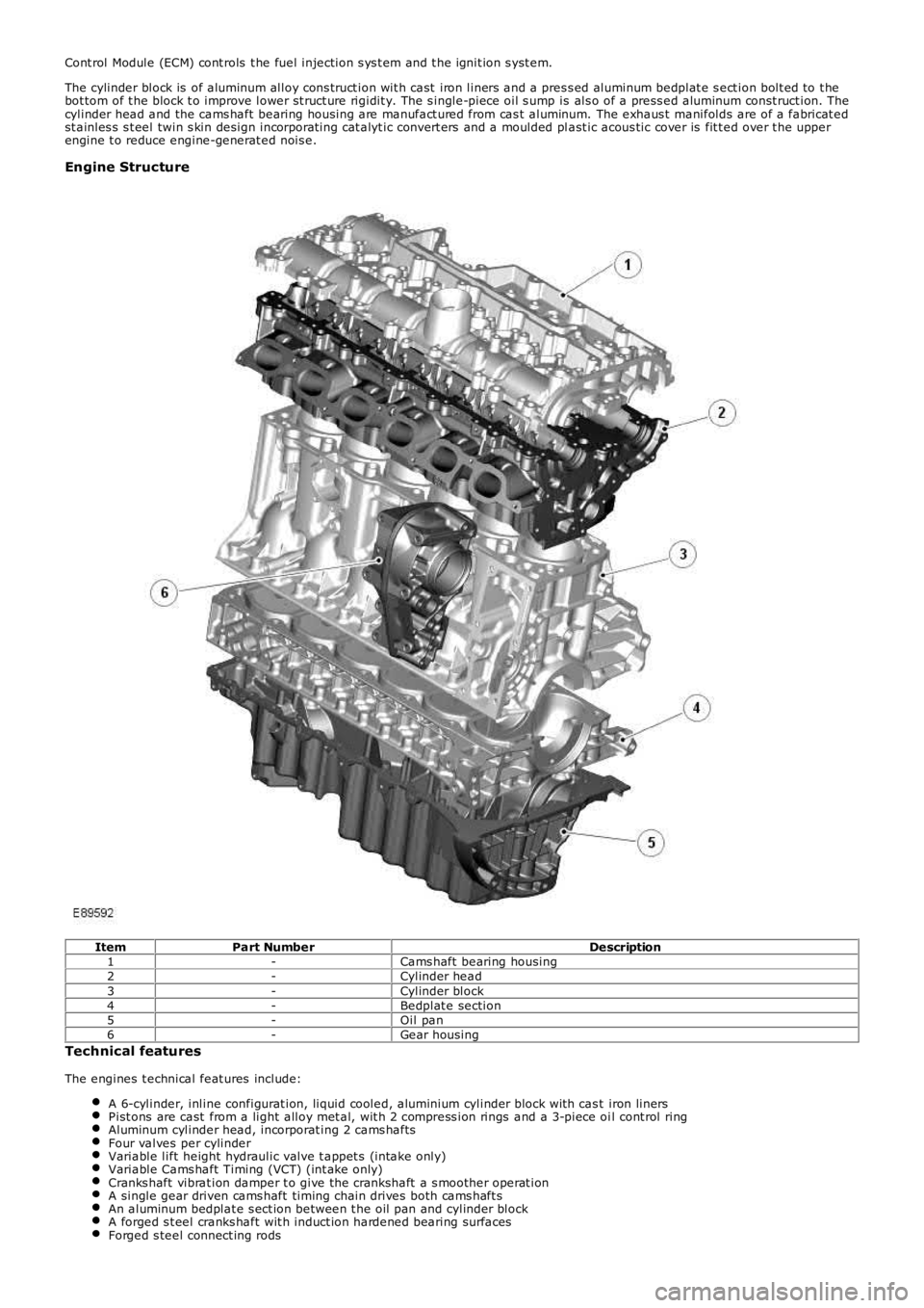
The cylinder block is of aluminum alloy cons truct ion wit h cast iron liners and a pres s ed aluminum bedplat e s ect ion bolt ed to t hebot tom of t he block t o improve lower st ruct ure rigidit y. The s ingle-piece oil s ump is als o of a press ed aluminum const ruct ion. Thecylinder head and the cams haft bearing housing are manufact ured from cas t aluminum. The exhaus t manifolds are of a fabricat edst ainles s s t eel twin s kin design incorporat ing cat alyt ic convert ers and a moulded plast ic acous tic cover is fit t ed over t he upperengine t o reduce engine-generat ed nois e.
Engine Structure
ItemPart NumberDescription1-Cams haft bearing housing2-Cylinder head3-Cylinder block4-Bedplat e section5-Oil pan6-Gear housing
Technical features
The engines t echnical feat ures include:
A 6-cylinder, inline configurat ion, liquid cooled, aluminium cylinder block wit h cast iron linersPist ons are cast from a light alloy met al, wit h 2 compress ion rings and a 3-piece oil cont rol ringAluminum cylinder head, incorporat ing 2 cams haftsFour valves per cylinderVariable lift height hydraulic valve t appet s (intake only)Variable Cams haft Timing (VCT) (int ake only)Cranks haft vibrat ion damper t o give the crankshaft a s moother operat ionA single gear driven cams haft timing chain drives both cams haft sAn aluminum bedplat e s ect ion between t he oil pan and cylinder blockA forged s t eel cranks haft wit h induct ion hardened bearing surfacesForged s teel connect ing rods
Page 607 of 3229
A Rear End Ancillary Drive (READ) s yst emTwo fabricated s t ainles s s t eel t win s kin exhaust manifoldsA 3-pos ition Variable Intake Sys t em (VIS)An advanced Engine Management Syst em (EMS) incorporat ing elect ronic t hrot tle controlFour cat alyt ic converters
Technical data
DESCR IPT IO NT YPEConfigurationInline 6-cylinderO utput171 kW at 6200 rpmT orque320 Nm at 3200 rpmDisplacement3192 cm³Stroke/bore96.0 mm/84.0 mmCompression ratio10.8:1Firing order1-5-3-6-2-4Approximate weight180 kg (including int ake pipe, exhaus t manifold, alt ernator and oil)
ItemPart NumberDescriptionA-Torque (Nm)B-Power (kW )
CYLINDER BLOCK COMPONENTS
The main cylinder block components are:
Cylinder blockConnect ing rods and pis tonsPist on cooling jet sGenerat orGear hous ingThermos tat hous ingCranks haft Pos it ion (CKP) s ensorKnock s ens orsCoolant pumpCoolant inlet pipe
Cylinder Numbering
The cylinders are numbered as shown below, wit h cylinder 1 at t he front of the engine.
Page 616 of 3229
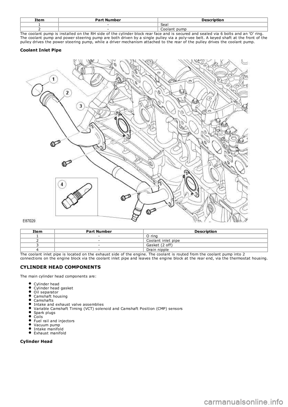
ItemPart NumberDescription1-Seal2-Coolant pumpThe coolant pump is ins t alled on t he RH side of t he cylinder block rear face and is s ecured and s ealed via 6 bolt s and an 'O' ring.The coolant pump and power s t eering pump are bot h driven by a single pulley via a poly-vee belt . A keyed s haft at the front of t hepulley drives t he power s teering pump, while a driver mechanism at t ached to t he rear of t he pulley drives the coolant pump.
Coolant Inlet Pipe
ItemPart NumberDescription1-O ring2-Coolant inlet pipe3-Gas ket (2 off)4-Drain nippleThe coolant inlet pipe is locat ed on t he exhaus t s ide of the engine. The coolant is rout ed from t he coolant pump int o 2connect ions on the engine block via t he coolant inlet pipe and leaves t he engine block at t he rear end, via t he t hermos tat hous ing.
CYLINDER HEAD COMPONENTS
The main cylinder head component s are:
Cylinder headCylinder head gas ketO il s eparat orCams haft hous ingCams haftsIntake and exhaust valve ass embliesVariable Cams haft Timing (VCT) s olenoid and Cams haft Posit ion (CMP) sens orsSpark plugsCoilsFuel rail and injectorsVacuum pumpIntake manifoldExhaus t manifold
Cylinder Head
Page 618 of 3229
ItemPart NumberDescription1-O il s eparat ion housingCrankcas e gas es are rout ed from t he crankcas e, engine block and cylinder head t o t he oil s eparat ion hous ing locat ed on t hecams haft cover. From the oil s eparat ion housing, t he crankcas e gas es are rout ed via a pres sure regulat or, locat ed at t he rear edgeof the hous ing, to the cylinder head and the intake port s for t he int ake valves .For addit ional information, refer t o: Evaporative Emis sions (303-13 Evaporative Emis sions , Descript ion and O perat ion).
Camshaft Housing
Page 619 of 3229
ItemPart NumberDescription1-Cams haft hous ing2-Cylinder headThe chill cas t cams haft hous ing is manufact ured from a light-alloy met al and act s as a combined valve cover and cams haft bearingcap. The hous ing has cas t oil duct s on it 's unders ide, which ensure good oil s upply t o t he camshaft s and t he valve lift ers . The oilseparat ion housing is locat ed on t he cams haft coverFor addit ional information, refer t o: Engine Emiss ion Cont rol - 3.2L (303-08 Engine Emis sion Cont rol - 3.2L NA - I6, Des cript ion andOperation)..
Camshafts
ItemPart NumberDescription1-Int ake cams haft
Page 625 of 3229
For addit ional information, refer t o: Elect ronic Engine Cont rols (303-14A Elect ronic Engine Controls - I6 3.2L Pet rol, Des cript ion andOperation).
Variable Camshaft Timing Solenoid and Camshaft Position Sensors
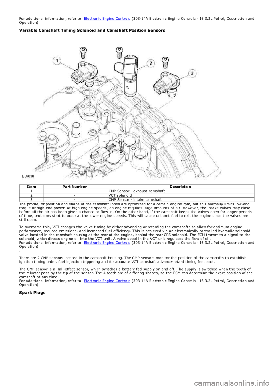
ItemPart NumberDescription1-CMP Sens or - exhaus t cams haft2-VCT s olenoid3-CMP Sens or - intake camshaftThe profile, or pos ition and shape of the cams haft lobes are opt imiz ed for a cert ain engine rpm, but this normally limit s low-endtorque or high-end power. At high engine s peeds , an engine requires large amounts of air. However, t he intake valves may clos ebefore all t he air has been given a chance t o flow in. On t he other hand, if the cams haft keeps t he valves open for longer periodsof time, problems st art t o occur at t he lower engine speeds . This will caus e unburnt fuel t o exit t he engine s ince t he valves arest ill open.
To overcome t his , VCT changes t he valve t iming by eit her advancing or ret arding the cams haft s t o allow for opt imum engineperformance, reduced emis s ions, and increased fuel efficiency. This is achieved via an electronically controlled hydraulic s olenoidvalve locat ed in t he camshaft housing at t he rear of t he engine, behind the rear CPS s olenoid. The ECM t rans mit s a signal t o thesolenoid, which direct s engine oil int o t he VCT unit. A valve s pool in the VCT unit regulat es t he flow of oil.For addit ional information, refer t o: Elect ronic Engine Cont rols (303-14A Elect ronic Engine Controls - I6 3.2L Pet rol, Des cript ion andOperation)..
There are 2 CMP s ens ors locat ed in t he camshaft housing. The CMP s ensors monitor the posit ion of the cams haft s t o est ablis hignit ion t iming order, fuel injection t riggering and for accurate VCT cams haft advance-retard t iming feedback.
The CMP sensor is a Hall-effect s ens or, which s wit ches a batt ery fed supply on and off. The s upply is s wit ched when t he t eet h ofthe reluct or pas s by t he tip of t he sens or. The 4 t eet h are of differing s hapes , s o the ECM can determine t he exact pos it ion of t hecams haft at any t ime.For addit ional information, refer t o: Elect ronic Engine Cont rols (303-14A Elect ronic Engine Controls - I6 3.2L Pet rol, Des cript ion andOperation).
Spark Plugs
Page 627 of 3229
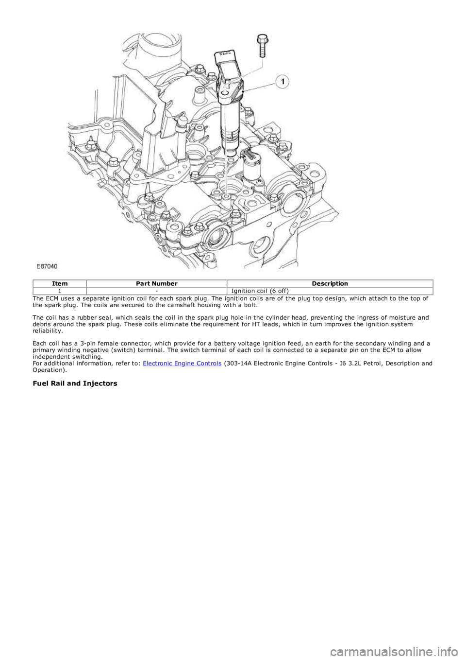
ItemPart NumberDescription1-Ignition coil (6 off)The ECM us es a s eparat e ignit ion coil for each spark plug. The ignit ion coils are of t he plug t op des ign, which at t ach t o t he t op ofthe s park plug. The coils are s ecured to the cams haft hous ing wit h a bolt.
The coil has a rubber seal, which s eals t he coil in the s park plug hole in t he cylinder head, prevent ing t he ingres s of mois t ure anddebris around t he spark plug. Thes e coils eliminat e t he requirement for HT leads , which in turn improves t he ignition s ys t emreliabilit y.
Each coil has a 3-pin female connect or, which provide for a bat tery volt age ignit ion feed, an eart h for t he s econdary winding and aprimary winding negat ive (s wit ch) terminal. The s wit ch t erminal of each coil is connect ed t o a separat e pin on t he ECM to allowindependent s wit ching.For addit ional information, refer t o: Elect ronic Engine Cont rols (303-14A Elect ronic Engine Controls - I6 3.2L Pet rol, Des cript ion andOperation).
Fuel Rail and Injectors
Page 630 of 3229
5-Bolt (2 of)6-Variable tract valveThe intake manifold att aches t o t he cylinder head wit h 6 bolt s and t he oil pan with 2 bolt s .
The manifold is capable of varying both int ake tract length and plenum volume by means of 2 separat e valves .
At low engine s peeds , long int ake tract s are ut iliz ed to provide opt imum engine t orque. Short er t racts are us ed at medium s peeds ,again, t o optimiz e engine t orque for t he exist ing engine s peed range.
At higher engine s peeds the benefit s of opt imizing t he t ract lengt hs are outweighed by the necess it y of maintaining anappropriate supply of air to meet t he engines requirement s . Therefore, t he plenum valve is opened t o create a s ingle, largeplenum volume to provide t he maximum quant ity of air t o charge the engines cylinders.For addit ional information, refer t o: Int ake Air Dis tribut ion and Filtering (303-12A Int ake Air Dis t ribution and Filt ering - I6 3.2LPet rol, Des cript ion and O perat ion).
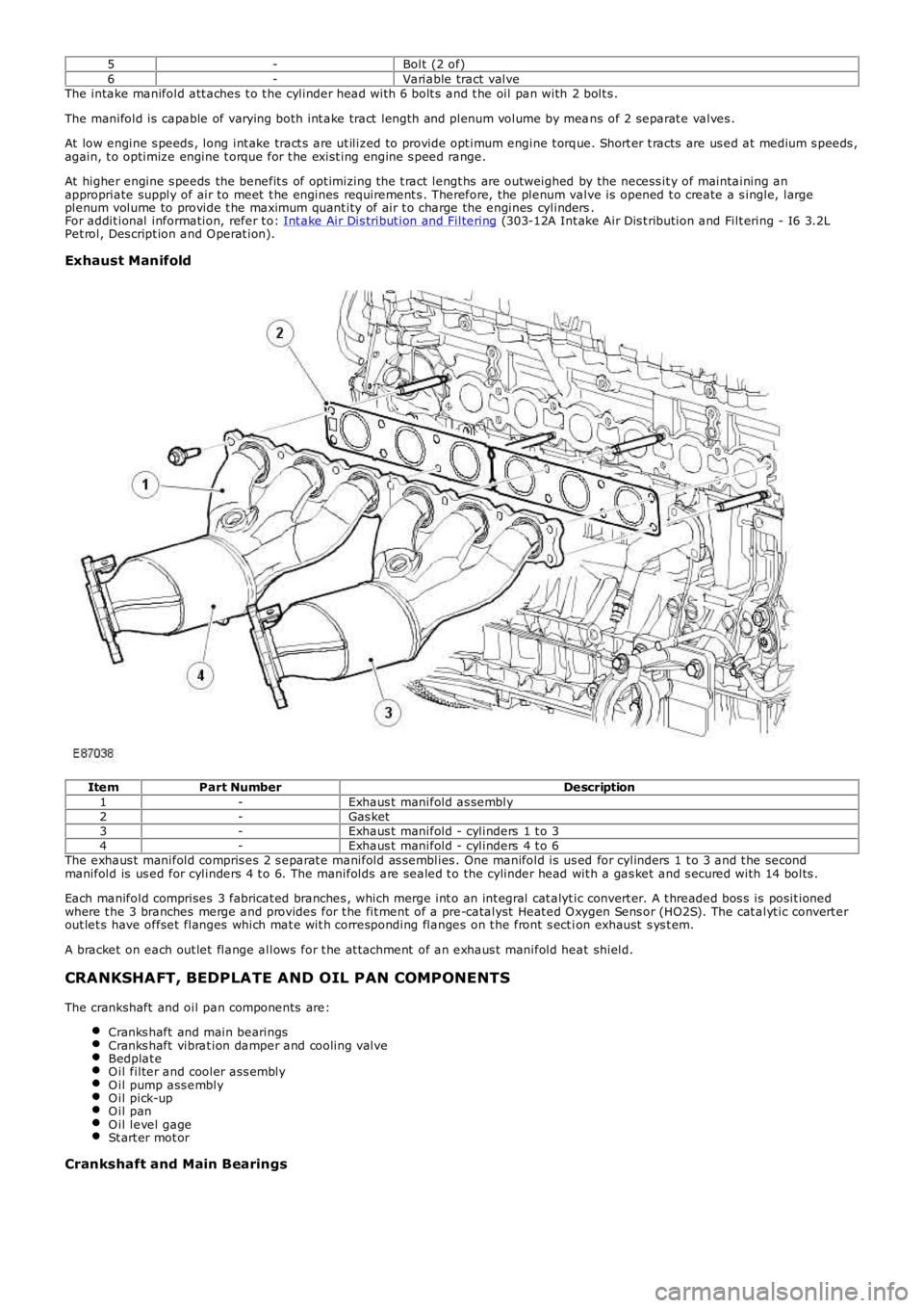
Exhaust Manifold
ItemPart NumberDescription1-Exhaus t manifold as sembly2-Gas ket3-Exhaus t manifold - cylinders 1 t o 34-Exhaus t manifold - cylinders 4 t o 6The exhaus t manifold compris es 2 s eparat e manifold as semblies . One manifold is us ed for cylinders 1 t o 3 and t he secondmanifold is us ed for cylinders 4 t o 6. The manifolds are sealed t o the cylinder head wit h a gas ket and s ecured with 14 bolts .
Each manifold comprises 3 fabricat ed branches , which merge int o an int egral cat alyt ic convert er. A t hreaded bos s is posit ionedwhere t he 3 branches merge and provides for t he fit ment of a pre-catalyst Heat ed O xygen Sens or (HO2S). The cat alyt ic convert erout let s have offset flanges which mat e wit h corresponding flanges on t he front s ect ion exhaust s ys t em.
A bracket on each out let flange allows for t he at t achment of an exhaus t manifold heat shield.
CRANKSHAFT, BEDPLATE AND OIL PAN COMPONENTS
The crankshaft and oil pan components are:
Cranks haft and main bearingsCranks haft vibrat ion damper and cooling valveBedplat eO il filter and cooler ass emblyO il pump ass emblyO il pick-upO il panO il level gageSt art er mot or
Crankshaft and Main Bearings