2006 DODGE RAM SRT-10 ESP
[x] Cancel search: ESPPage 2796 of 5267
When Monitored:
Initially at ignition on, then every 10 seconds thereafter. The solenoidswill also be tested immediately after a
gear ratio error or pressure switch error is detected.
Set Condition:
Three consecutive solenoid continuity test failures, or one failure if test is run in response to a gear ratio or
pressure switch error.
Possible Causes
RELATED TIPM TCM POWER CONTROL CIRCUIT DTCS PRESENT
(T59) UD SOLENOID CONTROL CIRCUIT OPEN
(T59) UD SOLENOID CONTROL CIRCUIT SHORT TO GROUND
(T59) UD SOLENOID CONTROL CIRCUIT SHORT TO VOLTAGE
TRANSMISSION SOLENOID/PRESSURE SWITCH ASSEMBLY
POWERTRAIN CONTROL MODULE
Always perform the 42RLE Pre-Diagnostic Troubleshooting procedure before proceeding. (Refer to 21 -
TRANSMISSION/TRANSAXLE/AUTOMATIC - 42RLE - STANDARD PROCEDURE)
Theory of Operation
Four solenoids are used to control the friction elements (clutches). The continuity of the solenoid circuits is period-
ically tested. Each solenoid is turned on or off depending on its current state. An inductive spike should be detected
by the PCM during this test. If no spike is detected, the circuit is tested again to verify the failure. In addition to the
periodic testing, the solenoid circuits are tested if a gear ratio or pressure switch error occurs. In this case, one
failure will result in the appropriateDTC being set. The MIL will illuminate and the transmission goes into neutral, if
the DTC is set above 35 Kmh (22 mph), Limp-in mode when vehicle speed is below35 Kmh (22 mph).
Diagnostic Test
1.DETERMINING IF RELATED TIPM TCM POWER CONTROL CIRCUIT DTCS PRESENT
With the scan tool, read TIPM DTCs.
Are there any TIPM TCM Power Control Circuit DTCs present also?
Ye s>>
Refer to the Transmission category and perform the appropriate symptom.
No>>
Go To 2
2.CHECK IF THE DTC IS CURRENT
With the scan tool, view DTCs.
Is the status Active or is the STARTS SINCE SET counter set at 0 for this DTC?
Ye s>>
Go To 3
No>>
Go To 7
3.CHECK THE PCM AND WIRING USING THE TRANSMISSION SIMULATOR
Turn the ignition off to the lock position.
Remove the Ignition Switch Feed fuse from the TIPM.
CAUTION: Removal of the Ignition Switch Feed fuse from the TIPM will prevent the vehicle from being
startedingear.
WARNING: The Ignition Switch Feed fuse must be removed from the TIPM. Failure to do so can result in
personal injury or death.
Install the Transmission Simulator,Miller tool #8333 and the ElectronicTransmission Adapter kit.
Ignition on, engine not running.
With the scan tool, actuate the UD Solenoid.
Page 2806 of 5267
When Monitored:
In any forward gear with engine speed above 1000 RPM, shortly after a shift and every minute thereafter.
Set Condition:
After a shift into a forward gear, with engine speed greater than 1000 RPM, the PCM momentarily turns on
element pressure to the clutch circuits that don’t have pressure to verifythat the correct pressure switch
closes. If the pressure switch does not close 2 times the DTC sets
Possible Causes
LOSS OF PRIME P0944 PRESENT
(T16) TRANSMISSION CONTROL OUTPUT CIRCUIT OPEN
(T47) 2/4 PRESSURE SWITCH SENSE CIRCUIT OPEN
(T47) 2/4 PRESSURE SWITCH CIRCUIT SHORT TO GROUND
(T47) 2/4 PRESSURE SWITCH SENSE CIRCUIT SHORT TO VOLTAGE
TRANSMISSION SOLENOID/PRESSURE SWITCH ASSEMBLY
INTERNAL TRANSMISSION
POWERTRAIN CONTROL MODULE
Always perform the 42RLE Pre-Diagnostic Troubleshooting procedure before proceeding. (Refer to 21 -
TRANSMISSION/TRANSAXLE/AUTOMATIC - 42RLE - STANDARD PROCEDURE)
Theory of Operation
Pressure switches are normally off or open (no pressure applied) and read high (+12 volts). When an element is
applied, the corresponding pressure switch closes to ground (0 volts) or turns on. The controller tests the OD and
24 pressure switches when they are off (when the corresponding friction element is not applied) by briefly applying
the OD and 24 elements which will cause the corresponding pressure switch to close. The test verifies that the
switches are operational and that the switch will close when the corresponding element is applied. If a switch fails
to respond, it is re-tested. The MIL illuminates and the transmission system defaults to Limp-in mode.
Diagnostic Test
1.CHECKING FOR LOSS OF PRIME DTC
With the scan tool, check for other Transmission DTCs.
Is the DTC P0944 present also?
Ye s>>
Refer to the Transmission category and perform the appropriate symptom.
No>>
Go To 2
2.CHECK FOR RELATED TRANSMISSION DTCS
With the scan tool, read Transmission DTCs.
Are any of the DTCs P0732, P0734 and/or P0846 present also?
Ye s>>
Replace the Transmission Solenoid/Pressure Switch Assembly per the Service Information.
Perform 42RLE TRANSMISSION VERIFICATION TEST - VER 1. (Refer to 21 - TRANSMISSION/
TRANSAXLE/AUTOMATIC - 42RLE - STANDARD PROCEDURE)
No>>
Go To 3
Page 2828 of 5267
When Monitored:
In any forward gear with engine speed above 1000 RPM, shortly after a shift and every minute thereafter.
Set Condition:
After a shift into a forward gear, with engine speed greater than 1000 RPM, the PCM momentarily turns on
element pressure to the clutch circuits that don’t have pressure to identify the correct pressure switch closes.
If the pressure switch does not close 2 times the DTC sets.
Possible Causes
LOSS OF PRIME P0944 PRESENT
(T16) TRANSMISSION CONTROL OUTPUT CIRCUIT OPEN
(T9) OD PRESSURE SWITCH SENSE CIRCUIT OPEN
(T9) OD PRESSURE SWITCH CIRCUIT SHORT TO GROUND
(T9) OD PRESSURE SWITCH SENSE CIRCUIT SHORT TO VOLTAGE
TRANSMISSION SOLENOID/PRESSURE SWITCH ASSEMBLY
INTERNAL TRANSMISSION
POWERTRAIN CONTROL MODULE
Always perform the 42RLE Pre-Diagnostic Troubleshooting procedure before proceeding. (Refer to 21 -
TRANSMISSION/TRANSAXLE/AUTOMATIC - 42RLE - STANDARD PROCEDURE)
Theory of Operation
Pressure switches are normally off or open (no pressure applied) and read high (+12 volts). When an element is
applied, the corresponding pressure switch closes to ground (0 volts) or turns on. The controller tests the OD and
2/4 pressure switches when they are off (when the corresponding friction element is not applied) by briefly applying
the OD and 2/4 elements which will cause the corresponding pressure switchto close. The test verifies that the
switches are operational and that the switch will close when the corresponding element is applied. If a switch fails
to respond, it is re-tested. The MIL illuminates and the transmission system defaults to Limp-in mode.
Diagnostic Test
1.CHECKING FOR LOSS OF PRIME DTC
With the scan tool, check for other Transmission DTCs.
Is the DTC P0944 present also?
Ye s>>
Refer to the Transmission category and perform the appropriate diagnostic procedure.
No>>
Go To 2
2.CHECK FOR RELATED TRANSMISSION DTCS
With the scan tool, read Transmission DTCs.
Are any of the DTCs P0732, P0734 and/or P0846 present also?
Ye s>>
Replace the Transmission Solenoid/Pressure Switch Assembly per the Service Information.
Perform 42RLE TRANSMISSION VERIFICATION TEST - VER 1. (Refer to 21 - TRANSMISSION/
TRANSAXLE/AUTOMATIC - 42RLE - STANDARD PROCEDURE)
No>>
Go To 3
Page 2864 of 5267
P0944-LOSS OF HYDRAULIC PUMP PRIME
For a complete wiring diagramRefer to Section 8W.
When Monitored:
Every 350 msec
Set Condition:
If the transmission begins to slip in any forward gear, and the pressure switch or switches that should be
closed for a given gear are open, a loss of prime test begins. All available elements (in 1st gear LR, 2/4 and
OD, in 2nd, 3rd, and 4th gear 2/4 and OD) are turned on by the PCM to see if pump prime exists. The code
is set if none of the pressure switches respond. The PCM will continue to runthe loss of prime test until pump
pressure returns. The vehicle will not move or the transmission will slip.Normal operation will continue if pump
prime returns.
Possible Causes
LOW TRANSMISSION FLUID LEVEL
SHIFT LEVER POSITION
PLUGGED TRANSMISSION FILTER
TRANSMISSION OIL PUMP
Always perform the 42RLE Pre-Diagnostic Troubleshooting procedure before proceeding. (Refer to 21 -
TRANSMISSION/TRANSAXLE/AUTOMATIC - 42RLE - STANDARD PROCEDURE)
Theory of Operation
The Loss of Prime Test is used to prevent transmission defaults and erroneous fault codes during temporary loss of
pump prime that may occur with low transmission fluid under severe brakingconditions, start-up, etc. and to point
towards more subtle problems such as a plugged or ruptured oil filter. The Loss of Prime fault is set by a loss of
hydraulic pressure in the transmission system. This condition, if sustained, will result in the vehicle being unable to
move.
Diagnostic Test
1.CHECK TO SEE IF DTC P0944 IS CURRENT
Place the gear selector in park.
Start the engine.
NOTE: The Transmission Temperature must be at least 43° C (110° F) before performing the following steps.
The Transmission must be at operating temperature prior to checking pressure. Cold transmission fluid will result in
higher pressure readings.
Place the Transmission in Reverse.
With the scan tool, observe the Transmission Pressure Switch states.
Are any of the Pressure Switches closed?
Ye s>>
Go To 2
No>>
Go To 4
Page 2866 of 5267
P0992-2/4/OD HYDRAULIC PRESSURE TEST
For a complete wiring diagramRefer to Section 8W.
When Monitored:
In any forward gear with engine speed above 1000 RPM, shortly after a shift and every minute thereafter.
Set Condition:
After a shift into a forward gear, with engine speed greater than 1000 RPM, the PCM momentarily turns on
element pressure to the clutch circuits that do not have pressure to identify that the correct pressure switch
closes. If the pressure switch does not close 2 times the DTC sets.
Possible Causes
CONDITION P0992 PRESENT
Always perform the Pre-Diagnostic Troubleshooting procedure before proceeding. (Refer to 21 - TRANSMIS-
SION/TRANSAXLE/AUTOMATIC - 42RLE - DIAGNOSIS AND TESTING).
Theory of Operation
Pressure switches are normally off or open (no pressure applied) and read high (+12 volts). When an element is
applied, the corresponding pressure switch closes to ground (0 volts) or turns on. The controller tests the OD and
2/4 pressure switches when they are off (when the corresponding friction element is not applied) by briefly applying
the OD and 2/4 elements which will cause the corresponding pressure switchto close. The test verifies that the
switches are operational and that the switch will close when the corresponding element is applied. If a switch fails
to respond, it is re-tested. The MIL illuminates and the transmission system defaults to Limp-in mode.
1.CHECK TO SEE IF DTC P0992 IS CURRENT
NOTE: The vehicle must be driven to set this DTC. The transmission must at operating temperature with the
Engine RPM above 1000 RPM.
This DTC is an indication of both the 2/4 and the O/D Hydraulic Pressure Switch DTCs present.
Perform the diagnostic procedures for both P0845 and P0870.
With the scan tool, check the DTC EVENT DATA to help identify the conditionsin which the DTC was set.
If there are no possible causes remaining, view repair.
Repair
Refer to the Transmission category and perform the diagnostic proceduresfor P0845 and P0870.
Page 2921 of 5267
HYDRAULIC PRESSURE TESTS
Pressure testing is a very important step in the diag-
nostic procedure. These tests usually reveal the cause
of most transmission problems.
Before performing pressure tests, be certain that fluid
level and condition, and shift cable adjustments have
been checked and approved. Fluid must be at operat-
ing temperature (150 to 200 degrees F.).
Install an engine tachometer, raise vehicle on hoist
which allows the wheels to turn, and position tachom-
eter so it can be read.
Using special adapters L-4559, attach 300 psi
gauge(s) C-3293SP to the port(s) required for test
being conducted.
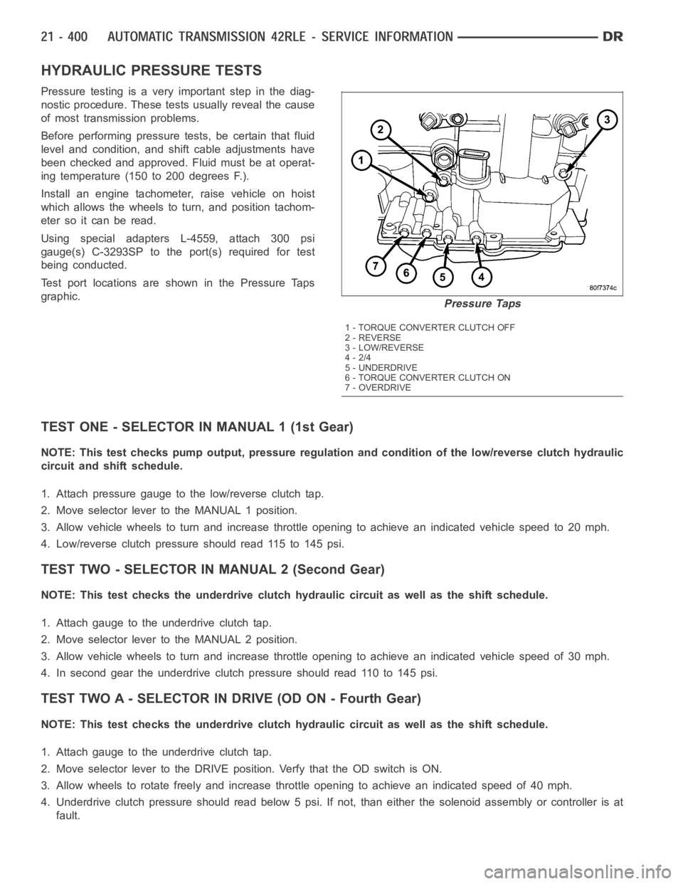
Test port locations are shown in the Pressure Taps
graphic.
TEST ONE - SELECTOR IN MANUAL 1 (1st Gear)
NOTE: This test checks pump output, pressure regulation and condition of the low/reverse clutch hydraulic
circuit and shift schedule.
1. Attach pressure gauge to the low/reverse clutch tap.
2. Move selector lever to the MANUAL 1 position.
3. Allow vehicle wheels to turn and increase throttle opening to achieve anindicatedvehiclespeedto20mph.
4. Low/reverse clutch pressure should read 115 to 145 psi.
TEST TWO - SELECTOR IN MANUAL 2 (Second Gear)
NOTE: This test checks the underdrive clutch hydraulic circuit as well as the shift schedule.
1. Attach gauge to the underdrive clutch tap.
2. Move selector lever to the MANUAL 2 position.
3. Allow vehicle wheels to turn and increase throttle opening to achieve anindicated vehicle speed of 30 mph.
4. In second gear the underdrive clutch pressure should read 110 to 145 psi.
TEST TWO A - SELECTOR IN DRIVE (OD ON - Fourth Gear)
NOTE: This test checks the underdrive clutch hydraulic circuit as well as the shift schedule.
1. Attach gauge to the underdrive clutch tap.
2. Move selector lever to the DRIVE position. Verfy that the OD switch is ON.
3. Allow wheels to rotate freely and increase throttle opening to achieve an indicated speed of 40 mph.
4. Underdrive clutch pressure should read below 5 psi. If not, than either the solenoid assembly or controller is at
fault.
Pressure Taps
1 - TORQUE CONVERTER CLUTCH OFF
2 - REVERSE
3 - LOW/REVERSE
4-2/4
5 - UNDERDRIVE
6 - TORQUE CONVERTER CLUTCH ON
7-OVERDRIVE
Page 2923 of 5267
5. Iftheunderdriveclutchpressureisgreaterthan5psiinStep4ofTestTwo-A, a defective solenoid/pressure
switch assembly or controller is the cause.
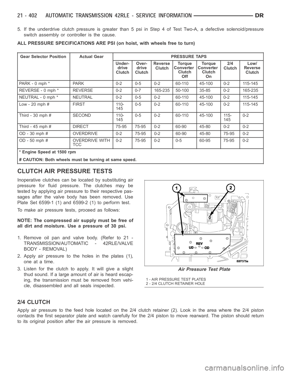
ALL PRESSURE SPECIFICATIONS ARE PSI (on hoist, with wheels free to turn)
Gear Selector Position Actual Gear PRESSURE TAPS
Under-
drive
ClutchOver-
drive
ClutchReverse
ClutchTo r q u e
Converter
Clutch
OffTo r q u e
Converter
Clutch
On2/4
ClutchLow/
Reverse
Clutch
PARK - 0 mph * PARK 0-2 0-5 0-2 60-110 45-100 0-2 115-145
REVERSE - 0 mph * REVERSE 0-2 0-7 165-235 50-100 35-85 0-2 165-235
NEUTRAL - 0 mph * NEUTRAL 0-2 0-5 0-2 60-110 45-100 0-2 115-145
Low - 20 mph # FIRST 110-
1450-5 0-2 60-110 45-100 0-2 115-145
Third-30mph# SECOND 110-
1450-5 0-2 60-110 45-100 115-
1450-2
Third - 45 mph # DIRECT 75-95 75-95 0-2 60-90 45-80 0-2 0-2
OD - 30 mph # OVERDRIVE 0-2 75-95 0-2 60-90 45-80 75-95 0-2
OD - 50 mph # OVERDRIVE WITH
TCC0-2 75-95 0-2 0-5 60-95 75-95 0-2
* Engine Speed at 1500 rpm
# CAUTION: Both wheels must be turning at same speed.
CLUTCH AIR PRESSURE TESTS
Inoperative clutches can be located by substituting air
pressure for fluid pressure. The clutches may be
tested by applying air pressure to their respective pas-
sages after the valve body has been removed. Use
Plate Set 6599-1 (1) and 6599-2 (1) to perform test.
To make air pressure tests, proceed as follows:
NOTE: The compressed air supply must be free of
all dirt and moisture. Use a pressure of 30 psi.
1. Remove oil pan and valve body. (Refer to 21 -
TRANSMISSION/AUTOMATIC - 42RLE/VALVE
BODY - REMOVAL)
2. Apply air pressure to the holes in the plates (1),
one at a time.
3. Listen for the clutch to apply. It will give a slight
thud sound. If a large amount of air is heard escap-
ing, the transmission must be removed from vehi-
cle, disassembled and all seals inspected.
2/4 CLUTCH
Apply air pressure to the feed hole located on the 2/4 clutch retainer (2). Look in the area where the 2/4 piston
contacts the first separator plate and watch carefully for the 2/4 piston tomoverearward.Thepistonshouldreturn
to its original position after the air pressure is removed.
Air Pressure Test Plate
1 - AIR PRESSURE TEST PLATES
2 - 2/4 CLUTCH RETAINER HOLE
Page 3007 of 5267

OPERATION
The function of an accumulator is to cushion the application of a frictional clutch element. When pressurized fluid is
applied to a clutch circuit, the application force is dampened by fluid collecting in the respective accumulator cham-
ber against the piston and springs. The intended result is a smooth, firm clutch application.