2006 DODGE RAM SRT-10 ESP
[x] Cancel search: ESPPage 2354 of 5267
PUMP - FUEL INJECTION
DESCRIPTION
A Robert Bosch high-pressure fuel injection pump is used. The pump is attached to the back of the timing gear
housing at the left /front side of the engine.
OPERATION
The fuel injection pump supplies high pressure to the fuel rail independent of engine speed. This high pressure is
then accumulated in the fuel rail. High pressure fuel is constantly supplied to the injectors by the fuel rail. The
Engine Control Module (ECM) controls the fueling and timing of the engine by actuating the injectors.
Fuel enters the system from the electric fuel transfer (lift) pump, which is located in the fuel tank. Fuel is forced
through the fuel filter element and then enters the Fuel Pump/Gear Pump, which is attached to the rear of the fuel
injection pump. The Fuel Pump/Gear Pump is a low-pressure pump and producepressures ranging from 551.5 kpa
(80 psi) to 1241 kpa (180) psi. Fuel then enters the fuel injection pump. Lowpressure fuel is then supplied to the
FCA (Fuel Control Actuator).
The FCA is an electronically controlled solenoid valve. The ECM controls the amount of fuel that enters the high-
pressure pumping chambers by opening and closing the FCA based on a demanded fuel pressure. The FPS (Fuel
Pressure Sensor) on the fuel rail provides the actual fuel pressure. When the actuator is opened, the maximum
amount of fuel is being supplied to the fuel injection pump. Any fuel that does not enter the injection pump is
directed to the cascade overflow valve. The cascade overflow valve regulates how much excess fuel is used for
lubrication of the pump and how much is returned to the tank through the drain manifold.
Fuel entering the injection pump is pressurized to between 300-1600 bar (4351-23206 psi) by three radial pumping
chambers. The pressurized fuel is then supplied to the fuel rail.
DIAGNOSIS AND TESTING
FUEL INJECTION PUMP TIMING
With the Bosch injection pump, there are no mechanical adjustments neededor necessary to accomplish fuel injec-
tion timing. All timing and fuel adjustments are electrically made by the engine mounted Engine Control Module
(ECM).
REMOVAL
CAUTION: Cleanliness cannot be overemphasized when handling or replacingdieselfuelsystemcompo-
nents. This especially includes the fuel injectors, high-pressure fuel lines and fuel injection pump. Very tight
tolerances are used with these parts. Dirt contamination could cause rapid part wear and possible plugging
of fuel injector nozzle tip holes. This in turn could lead to possible engine misfire. Always wash/clean any
fuel system component thoroughly before disassembly and then air dry. Capor cover any open part after
disassembly. Before assembly, examine each part for dirt, grease or othercontaminants and clean if nec-
essary. When installing new parts, lubricate them with clean engine oil orclean diesel fuel only.
Page 2357 of 5267
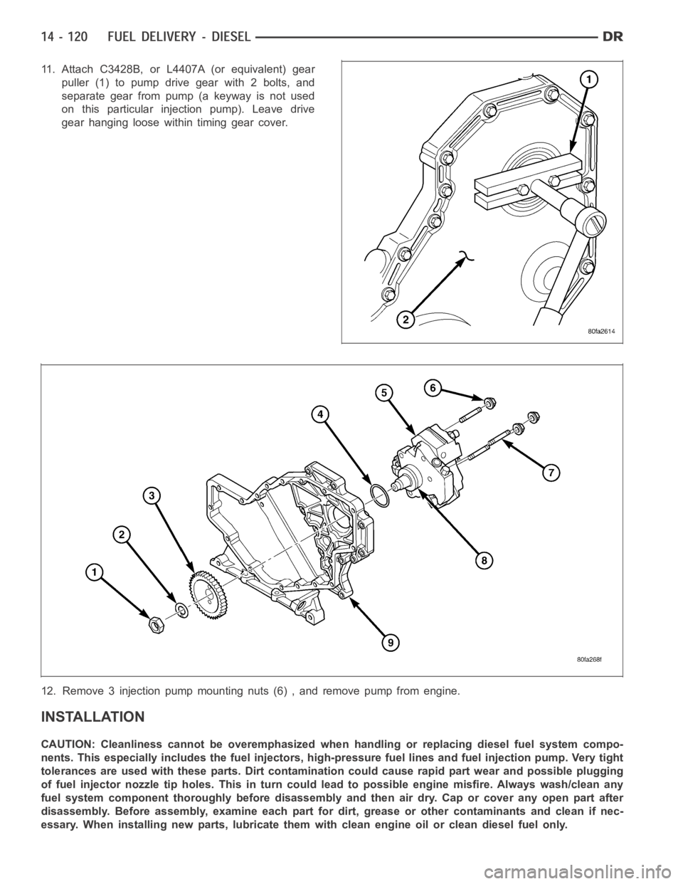
11. Attach C3428B, or L4407A (or equivalent) gear
puller (1) to pump drive gear with 2 bolts, and
separate gear from pump (a keyway is not used
on this particular injection pump). Leave drive
gear hanging loose within timing gear cover.
12. Remove 3 injection pump mounting nuts (6) , and remove pump from engine.
INSTALLATION
CAUTION: Cleanliness cannot be overemphasized when handling or replacingdieselfuelsystemcompo-
nents. This especially includes the fuel injectors, high-pressure fuel lines and fuel injection pump. Very tight
tolerances are used with these parts. Dirt contamination could cause rapid part wear and possible plugging
of fuel injector nozzle tip holes. This in turn could lead to possible engine misfire. Always wash/clean any
fuel system component thoroughly before disassembly and then air dry. Capor cover any open part after
disassembly. Before assembly, examine each part for dirt, grease or othercontaminants and clean if nec-
essary. When installing new parts, lubricate them with clean engine oil orclean diesel fuel only.
Page 2363 of 5267
REMOVAL
CAUTION: Cleanliness cannot be overemphasized when handling or replacingdieselfuelsystemcompo-
nents. This especially includes the fuel injectors, high-pressure fuel lines and fuel injection pump. Very tight
tolerances are used with these parts. Dirt contamination could cause rapid part wear and possible plugging
of fuel injector nozzle tip holes. This in turn could lead to possible engine misfire. Always wash/clean any
fuel system component thoroughly before disassembly and then air dry. Capor cover any open part after
disassembly. Before assembly, examine each part for dirt, grease or othercontaminants and clean if nec-
essary. When installing new parts, lubricate them with clean engine oil orclean diesel fuel only.
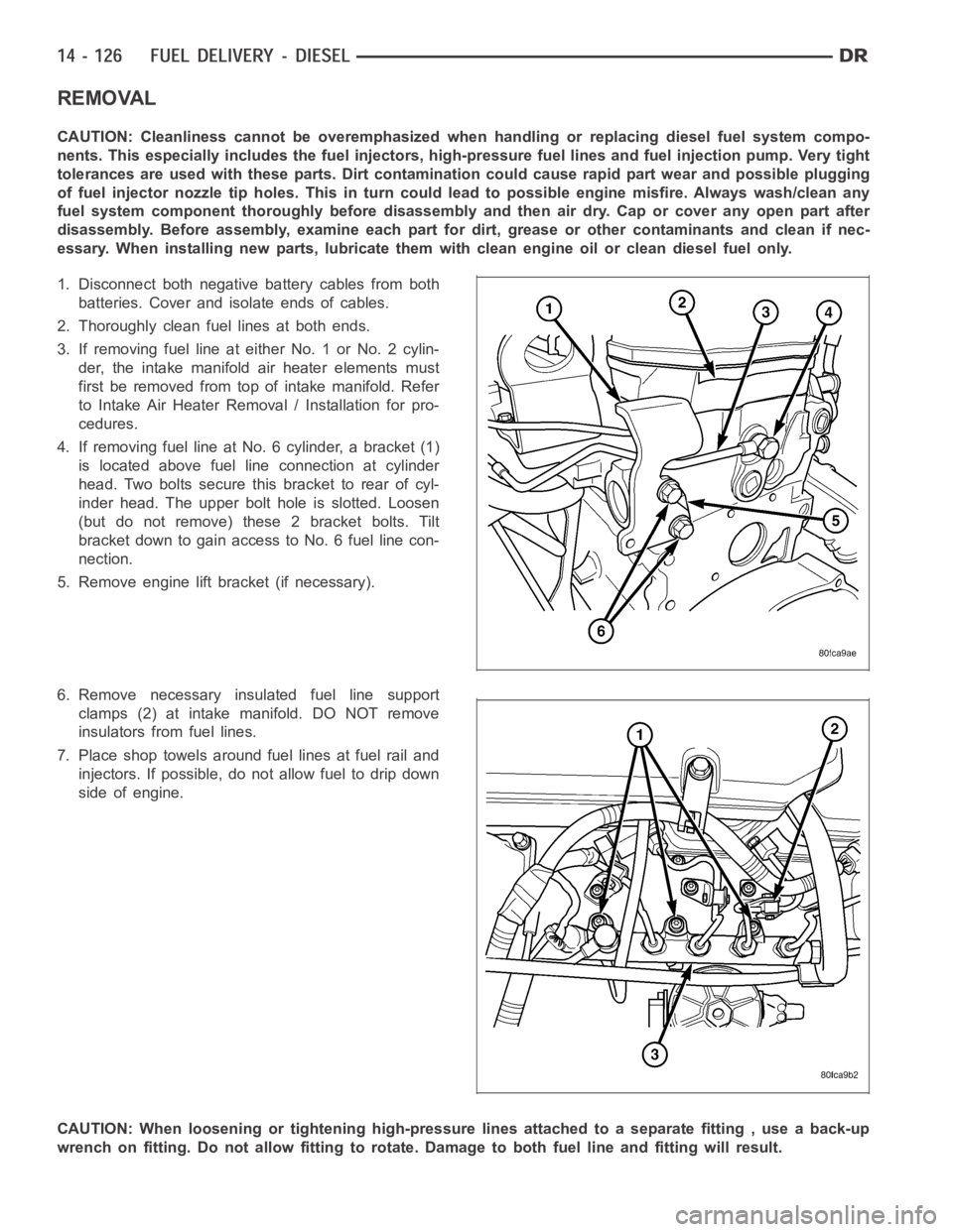
1. Disconnect both negative battery cables from both
batteries. Cover and isolate ends of cables.
2. Thoroughly clean fuel lines at both ends.
3. If removing fuel line at either No. 1 or No. 2 cylin-
der, the intake manifold air heater elements must
first be removed from top of intake manifold. Refer
to Intake Air Heater Removal / Installation for pro-
cedures.
4. If removing fuel line at No. 6 cylinder, a bracket (1)
is located above fuel line connection at cylinder
head. Two bolts secure this bracket to rear of cyl-
inder head. The upper bolt hole is slotted. Loosen
(but do not remove) these 2 bracket bolts. Tilt
bracket down to gain access to No. 6 fuel line con-
nection.
5. Remove engine lift bracket (if necessary).
6. Remove necessary insulated fuel line support
clamps (2) at intake manifold. DO NOT remove
insulators from fuel lines.
7. Place shop towels around fuel lines at fuel rail and
injectors. If possible, do not allow fuel to drip down
side of engine.
CAUTION: When loosening or tightening high-pressure lines attached to a separate fitting , use a back-up
wrench on fitting. Do not allow fitting to rotate. Damage to both fuel line and fitting will result.
Page 2367 of 5267
VALVE - FUEL PRESSURE LIMITING
DESCRIPTION
The fuel pressure limiting valve is located on the top of the fuel rail.
OPERATION
Fuel pressure at the fuel rail is monitored by the fuel rail pressure sensor. If fuel pressure becomes excessive, the
pressure limiting valve opens and vents excess pressure into the fuel draincircuit.
REMOVAL
CAUTION: Cleanliness cannot be overemphasized when handling or replacingdieselfuelsystemcompo-
nents. This especially includes the fuel injectors, high-pressure fuel lines and fuel injection pump. Very tight
tolerances are used with these parts. Dirt contamination could cause rapid part wear and possible plugging
of fuel injector nozzle tip holes. This in turn could lead to possible engine misfire. Always wash/clean any
fuel system component thoroughly before disassembly and then air dry. Capor cover any open part after
disassembly. Before assembly, examine each part for dirt, grease or othercontaminants and clean if nec-
essary. When installing new parts, lubricate them with clean engine oil orclean diesel fuel only.
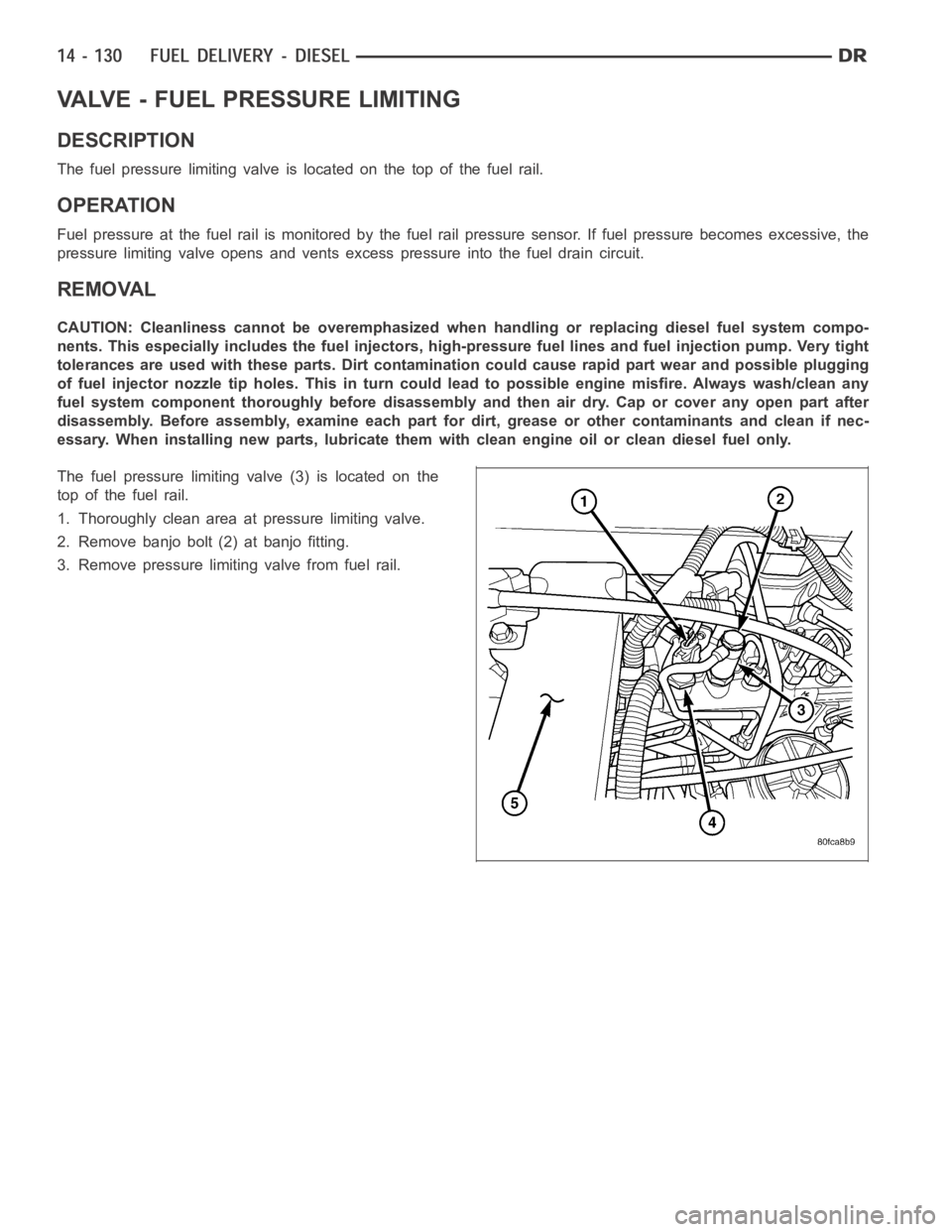
The fuel pressure limiting valve (3) is located on the
top of the fuel rail.
1. Thoroughly clean area at pressure limiting valve.
2. Remove banjo bolt (2) at banjo fitting.
3. Remove pressure limiting valve from fuel rail.
Page 2392 of 5267
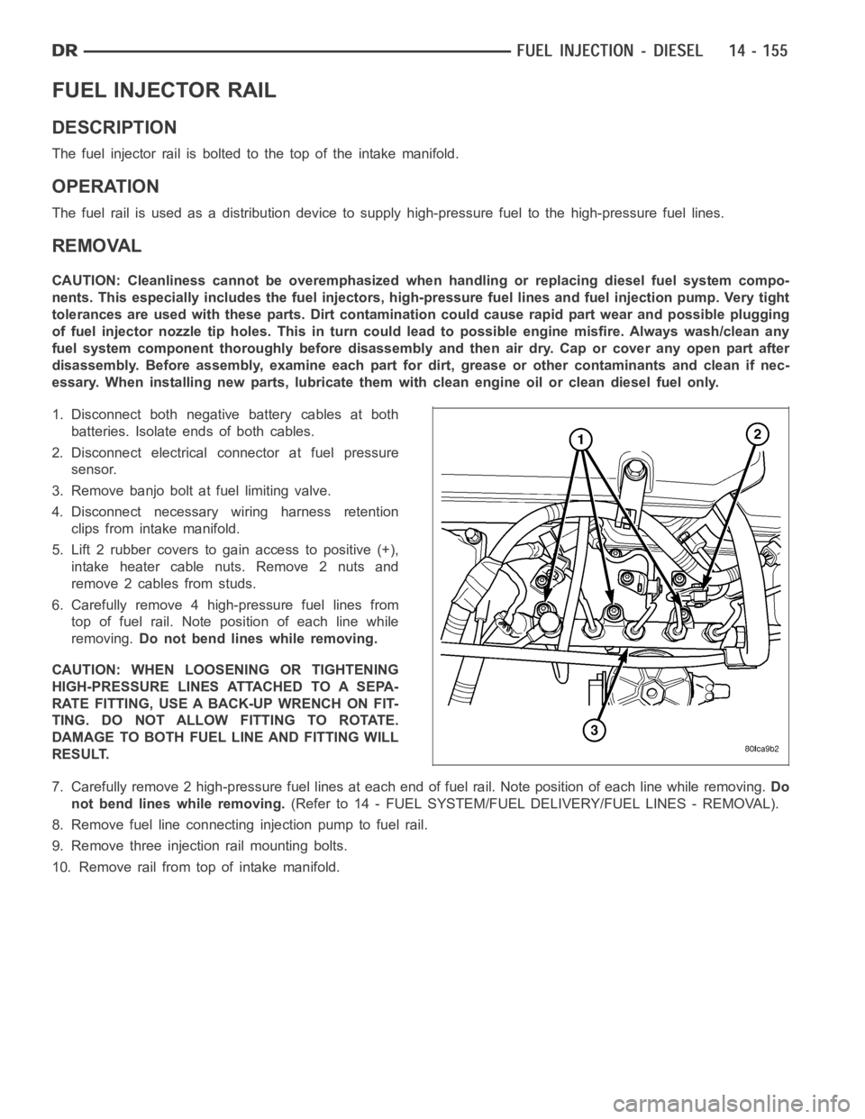
FUEL INJECTOR RAIL
DESCRIPTION
The fuel injector rail is bolted to the top of the intake manifold.
OPERATION
The fuel rail is used as a distribution device to supply high-pressure fuelto the high-pressure fuel lines.
REMOVAL
CAUTION: Cleanliness cannot be overemphasized when handling or replacingdieselfuelsystemcompo-
nents. This especially includes the fuel injectors, high-pressure fuel lines and fuel injection pump. Very tight
tolerances are used with these parts. Dirt contamination could cause rapid part wear and possible plugging
of fuel injector nozzle tip holes. This in turn could lead to possible engine misfire. Always wash/clean any
fuel system component thoroughly before disassembly and then air dry. Capor cover any open part after
disassembly. Before assembly, examine each part for dirt, grease or othercontaminants and clean if nec-
essary. When installing new parts, lubricate them with clean engine oil orclean diesel fuel only.
1. Disconnect both negative battery cables at both
batteries. Isolate ends of both cables.
2. Disconnect electrical connector at fuel pressure
sensor.
3. Remove banjo bolt at fuel limiting valve.
4. Disconnect necessary wiring harness retention
clips from intake manifold.
5. Lift 2 rubber covers to gain access to positive (+),
intake heater cable nuts. Remove 2 nuts and
remove 2 cables from studs.
6. Carefully remove 4 high-pressure fuel lines from
top of fuel rail. Note position of each line while
removing.Do not bend lines while removing.
CAUTION: WHEN LOOSENING OR TIGHTENING
HIGH-PRESSURE LINES ATTACHED TO A SEPA-
RATE FITTING, USE A BACK-UP WRENCH ON FIT-
TING. DO NOT ALLOW FITTING TO ROTATE.
DAMAGE TO BOTH FUEL LINE AND FITTING WILL
RESULT.
7. Carefully remove 2 high-pressure fuel lines at each end of fuel rail. Note position of each line while removing.Do
not bend lines while removing.(Refer to 14 - FUEL SYSTEM/FUEL DELIVERY/FUEL LINES - REMOVAL).
8. Remove fuel line connectinginjection pump to fuel rail.
9. Remove three injection rail mounting bolts.
10. Remove rail from top of intake manifold.
Page 2452 of 5267
ADJUSTMENTS
ADJUSTMENT
CAUTION: Steering gear must be adjusted in the proper order. If adjustments are not performed in order,
gear damage and improper steering response may result.
NOTE: Adjusting the steering gear in the vehicle is not recommended. Remove gear from the vehicle and
drain the fluid. Then mount gear in a vise to perform adjustments.
1. Remove the steering gear from the vehicle(Referto19-STEERING/GEAR-REMOVAL).
2. Mount the gear carefully into a soft-jawed vise.
CAUTION: Do not overtighten the vise on the gear case. This may affect the adjustment
3. Hold the steering gear upside down over a drain pan and rotate the input shaft back and forth several times
lock-to-lock to discharge the fluid from the steering gear
4. Rotate the input shaft to the left stop and then back-off approximately 45 degrees. Using an inch-pound torque
wrench on the input shaft, record the peak torque required to slowly and evenly rotate the input shaft clockwise
1⁄2turn (180 degrees) starting from the 45 degree position. This peak torque reading is the preload torque. The
preload torque must be within 2 - 10 in-lbs.
5. Rotate the input shaft to its center of travel (approximately 1.5 turns from either stop). Place the torque wrench
on the input shaft with the handle in the vertical position. Rotate the torque wrench slowly and evenly
1⁄4turn (90
degrees) each side of center and record the peak torque measure on or near center. This total on-center torque
reading must be 5 - 9 in-lbs higher than the previously measured preload torque without exceeding a total of 17
in-lbs. The value of the total on-center minus the preload torque is defined as the meshload torque
6. If required, adjust the on-center torque by loosening the adjuster screw lock nut and turning the adjuster screw
until the total on-center and meshload torque readings fall within the specified values. Turn the adjuster screw
clockwise to increase and counterclockwise to decrease the torque reading. While holding the adjuster screw in
place, tighten the lock nut to 34 Nꞏm (25 ft. lbs.).
7. Re-check the preload and on-center torque readings.
8. Install pitman arm on the steering gear (Refer to 19 - STEERING/LINKAGE/PITMAN ARM - INSTALLATION).
9. Reinstall steering gear to the vehicle (Refer to 19 - STEERING/GEAR - INSTALLATION).
SPECIFICATIONS
POWER STEERING GEAR
SPECIFICATIONS
DESCRIPTION SPECIFICATION
Steering Gear
Ty peRecirculating Ball
Gear Code & Ratio 12.5:1
TORQUE
DESCRIPTION Nꞏm Ft. Lbs. In. Lbs.
Preload
To r q u e0.23-1.13 — 2-10
Meshload Torque 0.56-1.02 — 5-9
+ Preload (17 Max)
Page 2487 of 5267
FLUID
DESCRIPTION
NOTE: It is normal that some pressure will build up inside the reservoir, especially, with a warm vehicle. A
slight popping noise upon removal ofthe cap is normal. The fluid level should read between the ADD and
the FULL COLD marks. When the fluid is hotit should read between ADD and FULLHOT marks. Only add
fluid when the vehicle is cold.
The recommended fluid for the power steering system is Mopar
AT F + 4 .
Mopar
ATF+4, when new is red in color. The ATF+4 is dyed red so it can be identified from other fluids used in the
vehicle such as engine oil or antifreeze. The red color is not permanent andis not an indicator of fluid condition, As
the vehicle is driven, the ATF+4 will begin to look darker in color and may eventually become brown.THIS IS NOR-
MAL.ATF+4 also has a unique odor that may change with age. Consequently, odor and color cannot be used to
indicate the fluid condition or the need for a fluid change.
STANDARD PROCEDURE
POWER STEERING FLUID LEVEL CHECKING
WARNING: FLUID LEVEL SHOULD BE CHECKED WITH THE ENGINE OFF TO PREVENT PERSONAL INJURY
FROM MOVING PARTS.
CAUTION: MOPAR
ATF+4 is to be used in the power steering system. No other power steering or auto-
matic transmission fluid is to be used in the system. Damage may result to the power steering pump and
system if any other fluid is used, and do not overfill.
The power steering fluid level can be viewed on the dipstick attached to thefiller cap. There are two ranges listed
on the dipstick, COLD and HOT. Before opening power steering system, wipe the reservoir filler cap free of dirt and
debris. Remove the cap and check the fluid level on its dipstick. When the fluid is at normal ambient temperature,
approximately 21°C to 27°C (70°F to 80°F), the fluid level should read between the minimum and maximum area of
the cold range. When the fluid is hot, fluid level is allowed to read up to thehighest end of the HOT range. Only add
fluid when the vehicle is cold.
Use only Mopar
AT F + 4 .Do not overfill the power steering system.
Page 2732 of 5267
P0218-HIGH TEMPERATURE OPERATION ACTIVATED
For a complete wiring diagramRefer to Section 8W.
When Monitored:
Whenever the engine is running.
Set Condition:
Immediately when a Overheat shift schedule is activated when the Transmission Oil Temperature reaches 155°
C or 240° F.
Possible Causes
ENGINE COOLING SYSTEM OPERATION
TRANSMISSION OIL COOLER PLUGGED
H I G H T E M P E R AT U R E O P E R AT I O N S A C T I VAT E D
Always perform the Pre-Diagnostic Troubleshooting procedure before proceeding. (Refer to 21 - TRANSMIS-
SION/TRANSAXLE/AUTOMATIC - 42RLE - STANDARD PROCEDURE)
Theory of Operation
If the transmission oil temperature rises above 115° C (240° F), the overheat shift schedule is activated refer to
Transmission Operation as a function of Transmission Oil Temperature andthe code is set. The DTC is an infor-
mational code only and is being set to aid the technician in determining root cause of a customer driveability issue.
The code is also intended to alert the technician to determine if a cooling system malfunction has occurred or if an
additional transmission air to oil cooler should be added to the vehicle ifthe customer regularly drives in a manner
that overheats the transmission. Extended operation above 115° C (240° F)will reduce the durability of the trans-
mission and should be avoided. Correcting the cooling system malfunctionor installing an additional transmission oil
cooler will improve transmission durability especially for customers who operate in city/construction stop and go traf-
fic, tow trailers regularly, drive aggressively in low gear or drive regularly in mountainous areas.
Diagnostic Test
1.CHECK ENGINE COOLING SYSTEM
Perform Engine Cooling System diagnostics per the Service Information.
Is the Engine Cooling System functioning properly?
Ye s>>
Go To 2
No>>
Repair the cause of the engine overheating. Refer to the Service Information for the related diagnostic
or repair procedures.
Perform 42RLE TRANSMISSION VERIFICATION TEST - VER 1. (Refer to 21 - TRANSMISSION/
TRANSAXLE/AUTOMATIC - 42RLE - STANDARD PROCEDURE)
2.TRANSMISSION OIL COOLER RESTRICTED
Check the Transmission Oil Cooler Flow in accordance with the Service Information.
Is the transmission oil cooler restricted or plugged?
Ye s>>
Go To 3
No>>
Repair the cause of the plugged Transmission Oil Cooler as necessary and repair or replace the Trans-
mission Oil Cooler per the Service Information.
Perform 42RLE TRANSMISSION VERIFICATION TEST - VER 1. (Refer to 21 - TRANSMISSION/
TRANSAXLE/AUTOMATIC - 42RLE - STANDARD PROCEDURE)