2006 DODGE RAM SRT-10 ESP
[x] Cancel search: ESPPage 1054 of 5267
Theory of Operation
The fuel feedback system will maintain a stoiciometric fuel/air mixture,14.7:1, by modifying the injector pulsewidth
according to the oxygen content of the exhaust gas. The PCM makes short termand long term fuel corrections to
maintain stoiciometric fuel/air ratio for best catalytic converter efficiency. Short term fuel correction is based on
upstream O2 sensor output and is designed for quick engine response. The long term fuel correction compensated
for variations in the engine specifications, sensor tolerances and component aging and is designed to correct rich
and lean conditions over a longer period of time.
When Monitored:
With the engine running in closed loop mode, the ambient/battery temperature above 20 deg. F and altitude
below 8500 ft.
Set Condition:
If the PCM multiplies short term compensation by long term adaptive and a certain percentage is exceeded for
two trips, a freeze frame is stored, the MIL illuminates and a trouble code is stored. Two Trip Fault. Three good
trips to turn off the MIL
Possible Causes
FUEL PRESSURE OUT OF SPECS
RESTRICTED FUEL SUPPLY LINE
FUEL PUMP INLET STRAINER PLUGGED
FUEL PUMP MODULE
O2 SENSOR
(K41) O2 SENSOR 1/1 SIGNAL CIRCUIT SHORTED TO GROUND
O2 SENSOR 1/1 HEATER OPERATION
TP SENSOR
MAP SENSOR
ECT SENSOR
ENGINE MECHANICAL CONDITION
FUEL FILTER/PRESSURE REGULATOR
PCM
Always perform the Pre-Diagnostic Troubleshooting procedure before proceeding. (Refer to 9 - ENGINE -
DIAGNOSIS AND TESTING).
Diagnostic Test
1.GOOD TRIP EQUAL TO ZERO
NOTE: Check for contaminates that may have damaged the O2 Sensor: contaminated fuel, unapproved sil-
icone, oil and coolant.
Ignition on, engine not running.
With the scan tool, read DTCs and record the related Freeze Frame data.
Is the Good Trip Counter displayed and equal to zero?
Ye s>>
Go To 2
No>>
Refer to the INTERMITTENT CONDITION Diagnostic Procedure.
Perform the POWERTRAIN VERIFICATION TEST. (Refer to 9 - ENGINE - STANDARD PROCEDURE)
Page 1061 of 5267
Theory of Operation
The fuel feedback system will maintain a stoiciometric fuel/air mixture,14.7:1, by modifying the injector pulsewidth
according to the oxygen content of the exhaust gas. The PCM makes short termand long term fuel corrections to
maintain stoiciometric fuel/air ratio for best catalytic converter efficiency. Short term fuel correction is based on
upstream O2 sensor output and is designed for quick engine response. The long term fuel correction compensated
for variations in the engine specifications, sensor tolerances and component aging and is designed to correct rich
and lean conditions over a longer period of time.
When Monitored:
With the engine running in closed loop mode, the ambient/battery temperature above 20 deg. F and altitude
below 8500 ft.
Set Condition:
If the PCM multiplies short term compensation by long term adaptive and a purge fuel multiplier and the result
is below a certain value for 30 seconds over two trips, a freeze frame is stored, the MIL illuminates and a
trouble code is stored. Two Trip Fault. Three good trips to turn off the MIL.
Possible Causes
O2 SENSOR
(K41) O2 SENSOR 1/1 SIGNAL CIRCUIT OPEN
(K41) O2 SENSOR 1/1 SIGNAL CIRCUIT SHORTED TO VOLTAGE
1/1 O2 SENSOR HEATER OPERATION
EVAP SYSTEM OPERATION
TP SENSOR VOLTAGE GREATER THAN 0.92 OF A VOLT WITH THROTTLE CLOSED
TP SENSOR
FUEL FILTER/PRESSURE REGULATOR
MAP SENSOR
ECT SENSOR
ENGINE MECHANICAL CONDITION
PCM
Always perform the Pre-Diagnostic Troubleshooting procedure before proceeding. (Refer to 9 - ENGINE -
DIAGNOSIS AND TESTING).
Diagnostic Test
1.GOOD TRIP EQUAL TO ZERO
NOTE: Check for contaminates that may have damaged the O2 Sensor: contaminated fuel, unapproved sil-
icone, oil and coolant.
Ignition on, engine not running.
With the scan tool, read DTCs and record the related Freeze Frame data.
NOTE: Any O2 Sensor, TPS, ECT, MAP, or EVAP DTCs must be repaired before continuing.
Is the Good Trip Counter displayed and equal to zero?
Ye s>>
Go To 2
No>>
Refer to the INTERMITTENT CONDITIONSymptom (Diagnostic Procedure).
Perform the POWERTRAIN VERIFICATION TEST. (Refer to 9 - ENGINE - STANDARD PROCEDURE)
Page 1067 of 5267
Theory of Operation
The fuel feedback system will maintain a stoiciometric fuel/air mixture,14.7:1, by modifying the injector pulsewidth
according to the oxygen content of the exhaust gas. The PCM makes short termand long term fuel corrections to
maintain stoiciometric fuel/air ratio for best catalytic converter efficiency. Short term fuel correction is based on
upstream O2 sensor output and is designed for quick engine response. The long term fuel correction compensated
for variations in the engine specifications, sensor tolerances and component aging and is designed to correct rich
and lean conditions over a longer period of time.
When Monitored:
With the engine running in closed loop mode, the ambient/battery temperature above 20 deg. F and altitude
below 8500 ft.
Set Condition:
If the PCM multiplies short term compensation by long term adaptive and a certain percentage is exceeded for
two trips, a freeze frame is stored, the MIL illuminates and a trouble code is stored. Two Trip Fault. Three good
trips to turn off the MIL.
Possible Causes
FUEL PRESSURE OUT OF SPECS
RESTRICTED FUEL SUPPLY LINE
FUEL PUMP INLET STRAINER PLUGGED
FUEL PUMP MODULE
O2 SENSOR
(K43) O2 SENSOR 2/1 SIGNAL CIRCUIT SHORTED TO GROUND
O2 SENSOR 2/1 HEATER OPERATION
TP SENSOR
MAP SENSOR
ECT SENSOR
ENGINE MECHANICAL CONDITION
FUEL FILTER/PRESSURE REGULATOR
PCM
Always perform the Pre-Diagnostic Troubleshooting procedure before proceeding. (Refer to 9 - ENGINE -
DIAGNOSIS AND TESTING).
Diagnostic Test
1.GOOD TRIP EQUAL TO ZERO
NOTE: Check for contaminates that may have damaged the O2 Sensor: contaminated fuel, unapproved sil-
icone, oil and coolant.
Ignition on, engine not running.
With the scan tool, read DTCs and record the related Freeze Frame data.
Is the Good Trip Counter displayed and equal to zero?
Ye s>>
Go To 2
No>>
Refer to the INTERMITTENT CONDITION Diagnostic Procedure.
Perform the POWERTRAIN VERIFICATION TEST. (Refer to 9 - ENGINE - STANDARD PROCEDURE)
Page 1074 of 5267

Theory of Operation
The fuel feedback system will maintain a stoiciometric fuel/air mixture,14.7:1, by modifying the injector pulsewidth
according to the oxygen content of the exhaust gas. The PCM makes short termand long term fuel corrections to
maintain stoiciometric fuel/air ratio for best catalytic converter efficiency. Short term fuel correction is based on
upstream O2 sensor output and is designed for quick engine response. The long term fuel correction compensated
for variations in the engine specifications, sensor tolerances and component aging and is designed to correct rich
and lean conditions over a longer period of time.
When Monitored:
With the engine running in closed loop mode, the ambient/battery temperature above 20 deg. F and altitude
below 8500 ft.
Set Condition:
If the PCM multiplies short term compensation by long term adaptive and a purge fuel multiplier and the result
is below a certain value for 30 seconds over two trips, a freeze frame is stored, the MIL illuminates and a
trouble code is stored. Two Trip Fault. Three good trips to turn off the MIL.
Possible Causes
O2 SENSOR
(K43) O2 SENSOR 2/1 SIGNAL CIRCUIT OPEN
(K43) O2 SENSOR 2/1 SIGNAL CIRCUIT SHORTED TO VOLTAGE
2/1 O2 SENSOR HEATER OPERATION
EVAP SYSTEM OPERATION
TP SENSOR VOLTAGE GREATER THAN 0.92 OF A VOLT WITH THROTTLE CLOSED
TP SENSOR
FUEL FILTER/PRESSURE REGULATOR
MAP SENSOR
ECT SENSOR
ENGINE MECHANICAL CONDITION
PCM
Always perform the Pre-Diagnostic Troubleshooting procedure before proceeding. (Refer to 9 - ENGINE -
DIAGNOSIS AND TESTING).
Diagnostic Test
1.GOOD TRIP EQUAL TO ZERO
NOTE: Check for contaminates that may have damaged the O2 Sensor: contaminated fuel, unapproved sil-
icone, oil and coolant.
Ignition on, engine not running.
With the scan tool, read DTCs and record the related Freeze Frame data.
NOTE: Any O2 Sensor, TPS, ECT, MAP, or EVAP DTCs must be repaired before continuing.
Is the Good Trip Counter displayed and equal to zero?
Ye s>>
Go To 2
No>>
Refer to the INTERMITTENT CONDITIONSymptom (Diagnostic Procedure).
Perform the POWERTRAIN VERIFICATION TEST. (Refer to 9 - ENGINE - STANDARD PROCEDURE)
Page 1262 of 5267
Theory of Operation
The upstream O2 sensor is used to detect the amount of oxygen in the exhaust gas before the gas enters the
catalytic converter. During the catalyst/O2 monitor test, the response rate (cycles/second) of the upstream O2 sen-
sor determines the sensor’s ability to achieve the tailpipe emissions limits. The response rate of the downstream O2
sensor relative to the upstream O2 sensor response rate measures the catalyst’s ability to store oxygen and is used
to infer the catalyst’s ability to achieve the tailpipe emissions limits.
When Monitored:
After engine warm up to 70°C (158°F), 180 seconds of open throttle operation, at a speed greater than 18 mph
and less than 55 mph, with the engine at 1200-1700 rpm and MAP vacuum between15.0 and 21.0 inches of
mercury (Hg).
Set Condition:
As catalyst efficiency deteriorates, the switch rate of the downstream O2sensor approaches that of the
upstream O2 sensor. If at any point during the test the switch ratio reachesa predetermined value a counter
is incremented by one. Three good trips to turn off the MIL.
Possible Causes
EXHAUST LEAK
ENGINE MECHANICAL
AGING O2 SENSOR
CATALYTIC CONVERTER
Always perform the Pre-Diagnostic Troubleshooting procedure before proceeding. (Refer to 9 - ENGINE -
DIAGNOSIS AND TESTING).
Diagnostic Test
1.ACTIVE DTC
NOTE: A new rear O2 Sensor along with an aging front O2 Sensor may cause the DTCtoset.Reviewthe
repair history of the vehicle before continuing.
NOTE: If an O2 Sensor DTC set along with the Catalytic Converter EfficiencyDTC diagnose the O2 Sensor
DTC(s) before continuing.
NOTE: Check for contaminants that may have damaged the O2 Sensor and Catalytic Converter: contami-
nated fuel, unapproved silicone, oil and coolant, repair necessary.
Ignition on, engine not running.
With a scan tool, read DTCs.
Is the DTC active at this time?
Ye s>>
Go To 2
No>>
Refer to the INTERMITTENT CONDITION Diagnostic Procedure.
Perform the POWERTRAIN VERIFICATION TEST. (Refer to 9 - ENGINE - STANDARD PROCEDURE)
Page 1265 of 5267

Theory of Operation
The upstream O2 sensor is used to detect the amount of oxygen in the exhaust gas before the gas enters the
catalytic converter. During the catalyst/O2 monitor test, the response rate (cycles/second) of the upstream O2 sen-
sor determines the sensor’s ability to achieve the tailpipe emissions limits. The response rate of the downstream O2
sensor relative to the upstream O2 sensor response rate measures the catalyst’s ability to store oxygen and is used
to infer the catalyst’s ability to achieve the tailpipe emissions limits.
When Monitored:
After engine warm up to 147 deg. F, 180 seconds of open throttle operation, at a speed greater than 20 mph,
with the engine at 1200-1700 rpm and MAP vacuum between 15.0 and 21.0 inchesof mercury (Hg).
Set Condition:
As catalyst efficiency deteriorates, the switch rate of the downstream O2sensor approaches that of the
upstream O2 sensor. If at any point during the test the switch ratio reachesa predetermined value a counter
is incremented by one. Three good trips to turn off the MIL.
Possible Causes
EXHAUST LEAK
ENGINE MECHANICAL
AGING O2 SENSOR
CATALYTIC CONVERTER
Always perform the Pre-Diagnostic Troubleshooting procedure before proceeding. (Refer to 9 - ENGINE -
DIAGNOSIS AND TESTING).
Diagnostic Test
1.ACTIVE DTC
NOTE: A new rear O2 Sensor along with an aging front O2 Sensor may cause the DTCtoset.Reviewthe
repair history of the vehicle before continuing.
NOTE: If an O2 Sensor DTC set along with the Catalytic Converter EfficiencyDTC diagnose the O2 Sensor
DTC(s) before continuing.
NOTE: Check for contaminants that may have damaged the O2 Sensor and Catalytic Converter: contami-
nated fuel, unapproved silicone, oil and coolant, repair necessary.
Ignition on, engine not running.
With a scan tool, read DTCs.
Is the DTC active at this time?
Ye s>>
Go To 2
No>>
Refer to the INTERMITTENT CONDITION Diagnostic Procedure.
Perform the POWERTRAIN VERIFICATION TEST. (Refer to 9 - ENGINE - STANDARD PROCEDURE)
2.VISUALLY INSPECT CATALYTIC CONVERTER
Inspect the Catalytic Converter for the following damage.
Damaged Catalytic Converter, dents or holes.
Severe discoloration caused by overheating the Catalytic Converter.
Catalytic Converter broken internally.
Leaking Catalytic Converter.
Were any problems found?
Ye s>>
Replace the Catalytic Converter. Repair the condition that may have caused the failure.
Perform the POWERTRAIN VERIFICATION TEST. (Refer to 9 - ENGINE - STANDARD PROCEDURE)
No>>
Go To 3
Page 1303 of 5267
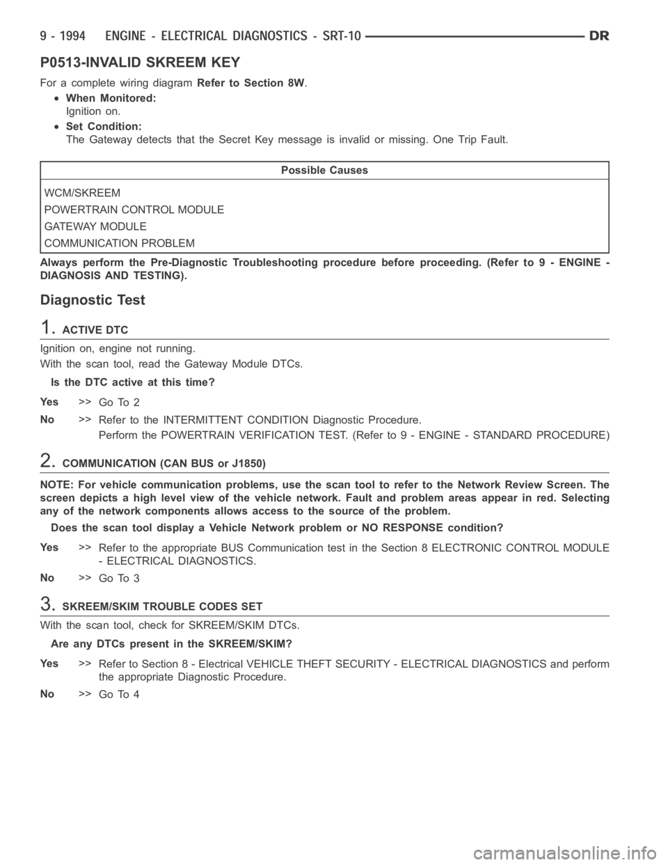
P0513-INVALID SKREEM KEY
For a complete wiring diagramRefer to Section 8W.
When Monitored:
Ignition on.
Set Condition:
The Gateway detects that the Secret Key message is invalid or missing. One Trip Fault.
Possible Causes
WCM/SKREEM
POWERTRAIN CONTROL MODULE
GATEWAY MODULE
COMMUNICATION PROBLEM
Always perform the Pre-Diagnostic Troubleshooting procedure before proceeding. (Refer to 9 - ENGINE -
DIAGNOSIS AND TESTING).
Diagnostic Test
1.ACTIVE DTC
Ignition on, engine not running.
With the scan tool, read the Gateway Module DTCs.
Is the DTC active at this time?
Ye s>>
Go To 2
No>>
Refer to the INTERMITTENT CONDITION Diagnostic Procedure.
Perform the POWERTRAIN VERIFICATION TEST. (Refer to 9 - ENGINE - STANDARD PROCEDURE)
2.COMMUNICATION (CAN BUS or J1850)
NOTE: For vehicle communication problems, use the scan tool to refer to theNetwork Review Screen. The
screen depicts a high level view of the vehicle network. Fault and problem areas appear in red. Selecting
any of the network components allows access to the source of the problem.
Does the scan tool display a Vehicle Network problem or NO RESPONSE condition?
Ye s>>
Refer to the appropriate BUS Communication test in the Section 8 ELECTRONIC CONTROL MODULE
- ELECTRICAL DIAGNOSTICS.
No>>
Go To 3
3.SKREEM/SKIM TROUBLE CODES SET
With the scan tool, check for SKREEM/SKIM DTCs.
Are any DTCs present in the SKREEM/SKIM?
Ye s>>
Refer to Section 8 - Electrical VEHICLE THEFT SECURITY - ELECTRICAL DIAGNOSTICS and perform
the appropriate Diagnostic Procedure.
No>>
Go To 4
Page 1496 of 5267
MoparGasket Maker is an anaerobic type gasket material. The material cures in the absence of air when
squeezed between two metallic surfaces. It will not cure if left in the uncovered tube. The anaerobic material is for
use between two machined surfaces. Do not use on flexible metal flanges.
MOPAR
GASKET SEALANT
Mopar
Gasket Sealant is a slow drying, permanently soft sealer. This material isrecommended for sealing
threaded fittings and gaskets against leakage of oil and coolant. Can be used on threaded and machined parts
under all temperatures. This material is used on engines with multi-layersteel (MLS) cylinder head gaskets. This
material also will prevent corrosion. Mopar
Gasket Sealant is available in a 13 oz. aerosol can or 4oz./16 oz. can
w/applicator.
FORM-IN-PLACE GASKET AND SEALER APPLICATION
Assembling parts using a form-in-place gasket requires care but it’s easier than using precut gaskets.
Mopar
Gasket Maker material should be applied sparingly 1 mm (0.040 in.) diameter or less of sealant to one
gasket surface. Be certain the material surrounds each mounting hole. Excess material can easily be wiped off.
Components should be torqued in place within 15 minutes. The use of a locating dowel is recommended during
assembly to prevent smearing material off the location.
Mopar
Engine RTV GEN II or ATF RTV gasket material should be applied in a continuous bead approximately 3
mm (0.120 in.) in diameter. All mounting holes must be circled. For corner sealing, a 3.17 or 6.35 mm (1/8 or 1/4 in.)
drop is placed in the center of the gasket contact area. Uncured sealant maybe removed with a shop towel. Com-
ponents should be torqued in place while the sealant is still wet to the touch (within 10 minutes). The usage of a
locating dowel is recommended during assembly to prevent smearing material off the location.
Mopar
Gasket Sealant in an aerosol can should be applied using a thin, even coat sprayed completely over both
surfaces to be joined, and both sides of a gasket. Then proceed with assembly. Material in a can w/applicator can
be brushed on evenly over the sealing surfaces. Material in an aerosol can shouldbeusedonengineswithmulti-
layer steel gaskets.
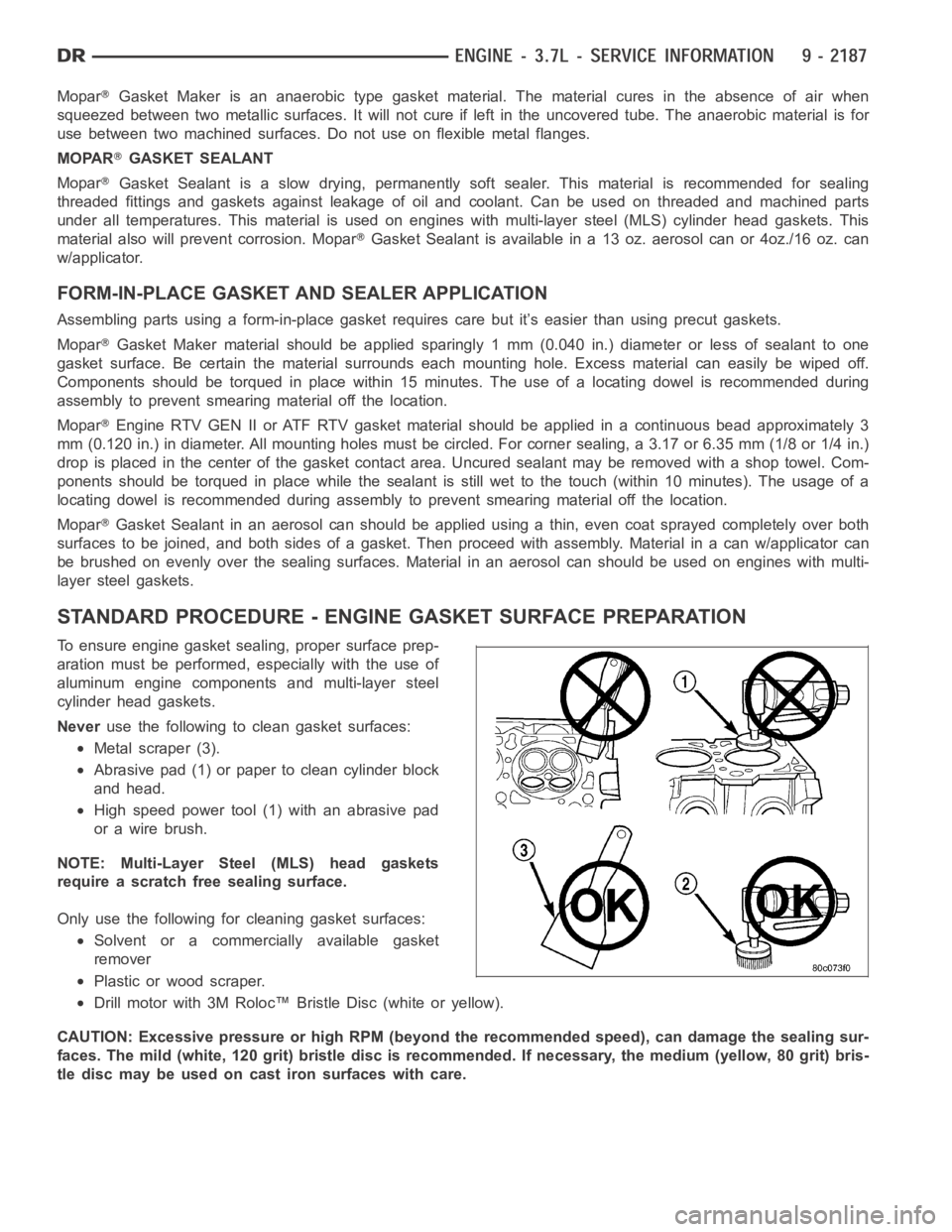
STANDARD PROCEDURE - ENGINE GASKET SURFACE PREPARATION
To ensure engine gasket sealing, proper surface prep-
aration must be performed, especially with the use of
aluminum engine components and multi-layer steel
cylinder head gaskets.
Neveruse the following to clean gasket surfaces:
Metal scraper (3).
Abrasive pad (1) or paper to clean cylinder block
and head.
High speed power tool (1) with an abrasive pad
orawirebrush.
NOTE: Multi-Layer Steel (MLS) head gaskets
require a scratch free sealing surface.
Only use the following for cleaning gasket surfaces:
Solvent or a commercially available gasket
remover
Plastic or wood scraper.
Drill motor with 3M Roloc™ Bristle Disc (white or yellow).
CAUTION: Excessive pressure or high RPM (beyond the recommended speed), can damage the sealing sur-
faces. The mild (white, 120 grit) bristle disc is recommended. If necessary, the medium (yellow, 80 grit) bris-
tle disc may be used on cast iron surfaces with care.