Page 905 of 5267

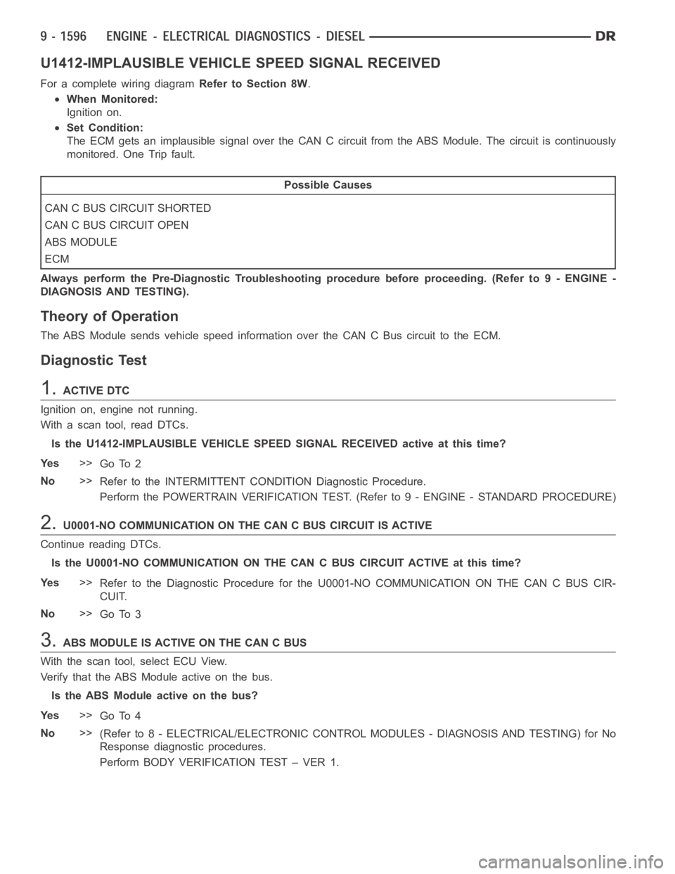
U1412-IMPLAUSIBLE VEHICLE SPEED SIGNAL RECEIVED
For a complete wiring diagramRefer to Section 8W.
When Monitored:
Ignition on.
Set Condition:
The ECM gets an implausible signal over the CAN C circuit from the ABS Module. The circuit is continuously
monitored. One Trip fault.
Possible Causes
CAN C BUS CIRCUIT SHORTED
CAN C BUS CIRCUIT OPEN
ABS MODULE
ECM
Always perform the Pre-Diagnostic Troubleshooting procedure before proceeding. (Refer to 9 - ENGINE -
DIAGNOSIS AND TESTING).
Theory of Operation
The ABS Module sends vehicle speed information over the CAN C Bus circuit tothe ECM.
Diagnostic Test
1.ACTIVE DTC
Ignition on, engine not running.
With a scan tool, read DTCs.
Is the U1412-IMPLAUSIBLE VEHICLE SPEED SIGNAL RECEIVED active at this time?
Ye s>>
Go To 2
No>>
Refer to the INTERMITTENT CONDITION Diagnostic Procedure.
Perform the POWERTRAIN VERIFICATION TEST. (Refer to 9 - ENGINE - STANDARD PROCEDURE)
2.U0001-NO COMMUNICATION ON THE CAN C BUS CIRCUIT IS ACTIVE
Continue reading DTCs.
Is the U0001-NO COMMUNICATION ON THE CAN C BUS CIRCUIT ACTIVE at this time?
Ye s>>
Refer to the Diagnostic Procedure for the U0001-NO COMMUNICATION ON THE CANCBUSCIR-
CUIT.
No>>
Go To 3
3.ABS MODULE IS ACTIVE ON THE CAN C BUS
With the scan tool, select ECU View.
Verify that the ABS Module active on the bus.
Is the ABS Module active on the bus?
Ye s>>
Go To 4
No>>
(Refer to 8 - ELECTRICAL/ELECTRONIC CONTROL MODULES - DIAGNOSIS AND TESTING) for No
Response diagnostic procedures.
Perform BODY VERIFICATION TEST – VER 1.
Page 911 of 5267

page page
ENGINE - ELECTRICAL DIAGNOSTICS - SRT-10
DIAGNOSIS AND TESTING
PRE-DIAGNOSTIC TROUBLESHOOTING
PROCEDURE............................. 1606
INTERMITTENT CONDITION ............... 1607
P0031-O2 SENSOR 1/1 HEATER CIRCUIT
LOW..................................... 1608
P0032-O2 SENSOR 1/1 HEATER CIRCUIT
HIGH.................................... 1612
P0051-O2 SENSOR 2/1 HEATER CIRCUIT
LOW..................................... 1616
P0052-O2 SENSOR 2/1 HEATER CIRCUIT
HIGH.................................... 1620
P0071-AMBIENT/BATTERY TEMP SENSOR
PERFORMANCE.......................... 1624
P0107-MAP SENSOR VOLTAGE TOO LOW . 1629
P0108–MAP SENSOR VOLTAGE TOO HIGH . 1634
P0111-INTAKE AIR TEMP PERFORMANCE . . 1639
P0112-INTAKE AIR TEMP SENSOR
VOLTAGE TOO LOW...................... 1643
P0113-INTAKE AIR TEMPERATURE
SENSOR CIRCUIT HIGH.................. 1647
P0117-ENGINE COOLANT TEMPERATURE
SENSOR CIRCUIT LOW................... 1651
P0118-ENGINE COOLANT TEMP SENSOR
VOLTAGE TOO HIGH...................... 1655
P0121-TP SENSOR VOLTAGE DOES NOT
AGREE WITH MAP........................ 1659
P0122-THROTTLE POSITION SENSOR #1
VOLTAGE TOO LOW...................... 1667
P0123-THROTTLE POSITION SENSOR #1
VOLTAGE TOO HIGH...................... 1672
P0125-INSUFFICIENT COOLANT TEMP FOR
CLOSED-LOOP FUEL CONTROL........... 1677
P0131-O2 SENSOR 1/1 CIRCUIT VOLTAGE
TOO LOW................................ 1680
P0132-O2 SENSOR 1/1 CIRCUIT VOLTAGE
TOO HIGH............................... 1683
P0133-O2 SENSOR 1/1 SLOW RESPONSE . 1688
P0135-O2 SENSOR 1/1 HEATER
PERFORMANCE.......................... 1691
P0136-O2 SENSOR 1/2 HEATER CIRCUIT
MALFUNCTION........................... 1694
P0137-O2 SENSOR 1/2 CIRCUIT LOW ..... 1697
P0138-O2 SENSOR 1/2 CIRCUIT HIGH ..... 1701
P0139-O2 SENSOR 1/2 SLOW RESPONSE . 1706
P0141-O2 SENSOR 1/2 HEATER
PERFORMANCE.......................... 1709
P0151-O2 SENSOR 2/1 CIRCUIT LOW ..... 1713
P0152-O2 SENSOR 2/1 CIRCUIT HIGH ..... 1716
P0153-O2 SENSOR 2/1 SLOW RESPONSE . 1721P0155-O2 SENSOR 2/1 HEATER
PERFORMANCE.......................... 1724
P0157-O2 SENSOR 2/2 CIRCUIT VOLTAGE
TOO LOW................................ 1728
P0158-O2 SENSOR 2/2 CIRCUIT VOLTAGE
TOO HIGH............................... 1732
P0159-O2 SENSOR 2/2 SLOW RESPONSE . 1737
P0161-O2 SENSOR 2/2 HEATER
PERFORMANCE.......................... 1740
P0171-FUEL SYSTEM 1/1 LEAN ........... 1744
P0172-FUEL SYSTEM 1/1 RICH ............ 1751
P0174-FUEL SYSTEM 2/1 LEAN ........... 1757
P0175-FUEL SYSTEM 2/1 RICH ............ 1764
P0197-ENGINE OIL TEMPERATURE
SENSOR VOLTAGE TOO LOW............. 1770
P0198-ENGINE OIL TEMPERATURE
SENSOR VOLTAGE TOO HIGH............ 1773
P0201-FUEL INJECTOR 1 CIRCUIT ........ 1777
P0202-FUEL INJECTOR 2 CIRCUIT ........ 1781
P0203-FUEL INJECTOR 3 CIRCUIT ........ 1785
P0204-FUEL INJECTOR 4 CIRCUIT ........ 1789
P0205-FUEL INJECTOR 5 CIRCUIT ........ 1793
P0206-FUEL INJECTOR 6 CIRCUIT ........ 1797
P0207-FUEL INJECTOR 7 CIRCUIT ........ 1801
P0208-FUEL INJECTOR 8 CIRCUIT ........ 1805
P0209-FUEL INJECTOR 9 CIRCUIT ........ 1809
P0210-FUEL INJECTOR 10 CIRCUIT....... 1813
P0300-MULTIPLE CYLINDER MISFIRE ..... 1817
P0301-CYLINDER #1 MISFIRE ............. 1823
P0302-CYLINDER #2 MISFIRE ............. 1832
P0303-CYLINDER #3 MISFIRE ............. 1841
P0304-CYLINDER #4 MISFIRE ............. 1850
P0305-CYLINDER #5 MISFIRE ............. 1859
P0306-CYLINDER #6 MISFIRE ............. 1868
P0307-CYLINDER #7 MISFIRE ............. 1877
P0308-CYLINDER #8 MISFIRE ............. 1886
P0309-CYLINDER #9 MISFIRE ............. 1895
P0310-CYLINDER #10 MISFIRE ............ 1904
P0320–NO CANK REFERENCE SIGNAL AT
PCM..................................... 1913
P0325-KNOCK SENSOR 1 CIRCUIT ........ 1921
P0330-KNOCK SENSOR 2 CIRCUIT ........ 1925
P0340-CAMSHAFT POSITION SENSOR
CIRCUIT................................. 1929
P0352-IGNITION COIL #2 PRIMARY
CIRCUIT................................. 1936
P0353-IGNITION COIL #3 PRIMARY
CIRCUIT................................. 1940
P0354-IGNITION COIL #4 PRIMARY
CIRCUIT................................. 1944
Page 915 of 5267

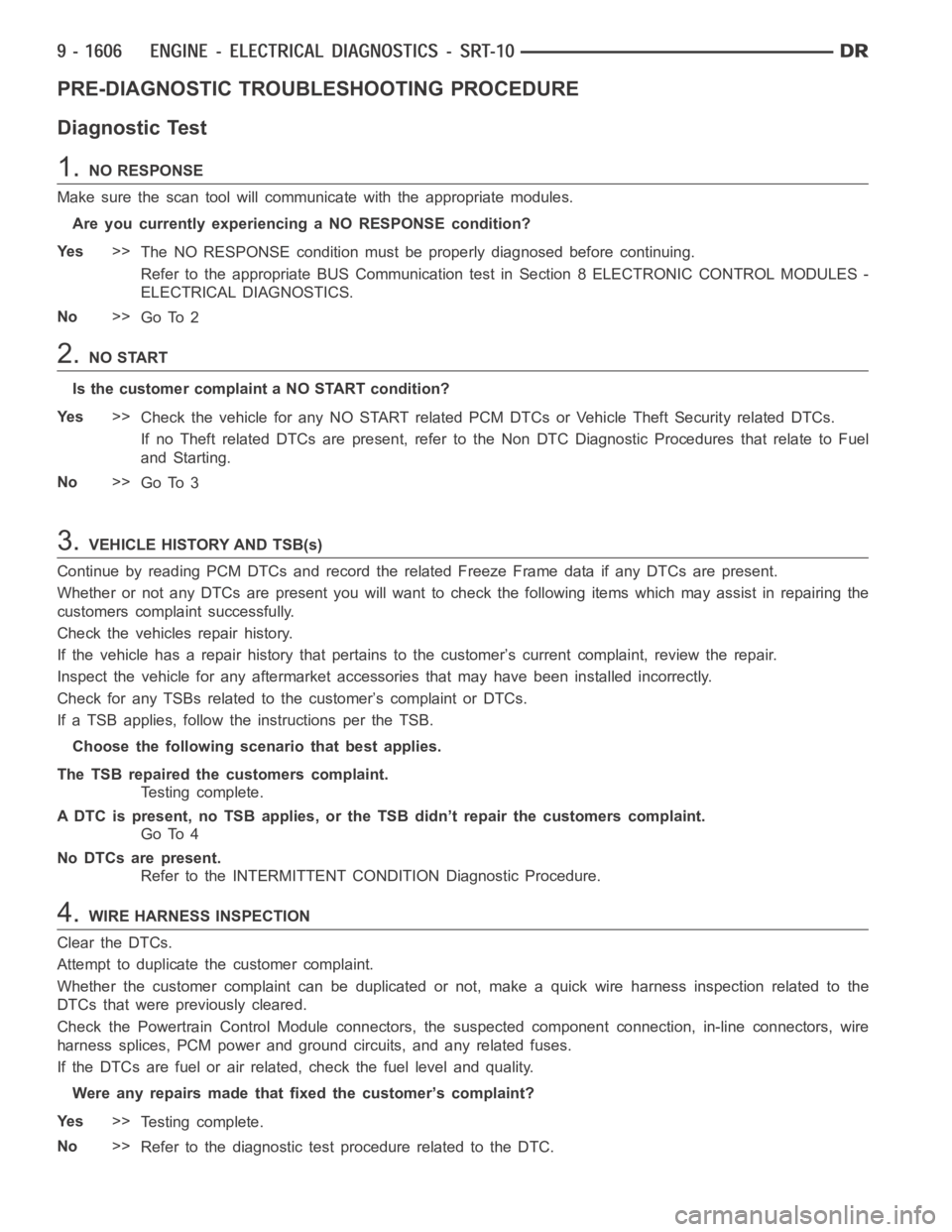
PRE-DIAGNOSTIC TROUBLESHOOTING PROCEDURE
Diagnostic Test
1.NO RESPONSE
Make sure the scan tool will communicate with the appropriate modules.
Are you currently experiencing a NO RESPONSE condition?
Ye s>>
The NO RESPONSE condition must be properly diagnosed before continuing.
Refer to the appropriate BUS Communication test in Section 8 ELECTRONIC CONTROL MODULES -
ELECTRICAL DIAGNOSTICS.
No>>
Go To 2
2.NO START
Is the customer complaint a NO START condition?
Ye s>>
Check the vehicle for any NO START related PCM DTCs or Vehicle Theft Security related DTCs.
If no Theft related DTCs are present, refer to the Non DTC Diagnostic Procedures that relate to Fuel
and Starting.
No>>
Go To 3
3.VEHICLE HISTORY AND TSB(s)
Continue by reading PCM DTCs and record the related Freeze Frame data if anyDTCs are present.
Whether or not any DTCs are present you will want to check the following items which may assist in repairing the
customers complaint successfully.
Check the vehicles repair history.
If the vehicle has a repair history that pertains to the customer’s currentcomplaint, review the repair.
Inspect the vehicle for any aftermarket accessories that may have been installed incorrectly.
Check for any TSBs related to thecustomer’s complaint or DTCs.
If a TSB applies, follow the instructions per the TSB.
Choose the following scenario that best applies.
The TSB repaired the customers complaint.
Testing complete.
A DTC is present, no TSB applies, or the TSB didn’t repair the customers complaint.
Go To 4
No DTCs are present.
Refer to the INTERMITTENT CONDITION Diagnostic Procedure.
4.WIRE HARNESS INSPECTION
Clear the DTCs.
Attempt to duplicate the customer complaint.
Whether the customer complaint can be duplicated or not, make a quick wire harness inspection related to the
DTCs that were previously cleared.
Check the Powertrain Control Module connectors, the suspected componentconnection, in-line connectors, wire
harness splices, PCM power and ground circuits, and any related fuses.
If the DTCs are fuel or air related, check the fuel level and quality.
Were any repairs made that fixed the customer’s complaint?
Ye s>>
Testing complete.
No>>
Refer to the diagnostic test procedure related to the DTC.
Page 997 of 5267
P0133-O2 SENSOR 1/1 SLOW RESPONSE
For a complete wiring diagramRefer to Section 8W.
Page 1015 of 5267
P0139-O2 SENSOR 1/2 SLOW RESPONSE
For a complete wiring diagramRefer to Section 8W.
Page 1016 of 5267

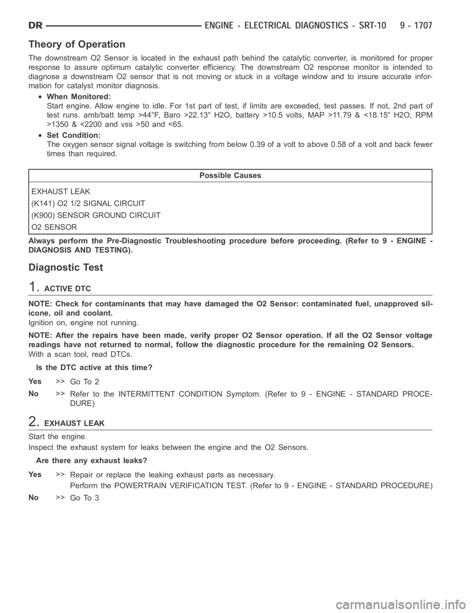
Theory of Operation
The downstream O2 Sensor is located in the exhaust path behind the catalytic converter, is monitored for proper
response to assure optimum catalytic converter efficiency. The downstream O2 response monitor is intended to
diagnose a downstream O2 sensor that is not moving or stuck in a voltage window and to insure accurate infor-
mation for catalyst monitor diagnosis.
When Monitored:
Start engine. Allow engine to idle. For 1st part of test, if limits are exceeded, test passes. If not, 2nd part of
test runs. amb/batt temp >44°F, Baro >22.13
H2O, battery >10.5 volts, MAP >11.79 & <18.15H2O, RPM
>1350 & <2200 and vss >50 and <65.
Set Condition:
The oxygen sensor signal voltage is switching from below 0.39 of a volt to above 0.58 of a volt and back fewer
times than required.
Possible Causes
EXHAUST LEAK
(K141) O2 1/2 SIGNAL CIRCUIT
(K900) SENSOR GROUND CIRCUIT
O2 SENSOR
Always perform the Pre-Diagnostic Troubleshooting procedure before proceeding. (Refer to 9 - ENGINE -
DIAGNOSIS AND TESTING).
Diagnostic Test
1.ACTIVE DTC
NOTE: Check for contaminants that may have damaged the O2 Sensor: contaminated fuel, unapproved sil-
icone, oil and coolant.
Ignition on, engine not running.
NOTE: After the repairs have been made, verify proper O2 Sensor operation.If all the O2 Sensor voltage
readings have not returned to normal, follow the diagnostic procedure forthe remaining O2 Sensors.
With a scan tool, read DTCs.
Is the DTC active at this time?
Ye s>>
Go To 2
No>>
Refer to the INTERMITTENT CONDITION Symptom. (Refer to 9 - ENGINE - STANDARD PROCE-
DURE)
2.EXHAUST LEAK
Start the engine.
Inspect the exhaust system for leaks between the engine and the O2 Sensors.
Are there any exhaust leaks?
Ye s>>
Repair or replace the leaking exhaust parts as necessary.
Perform the POWERTRAIN VERIFICATION TEST. (Refer to 9 - ENGINE - STANDARD PROCEDURE)
No>>
Go To 3
Page 1030 of 5267
P0153-O2 SENSOR 2/1 SLOW RESPONSE
For a complete wiring diagramRefer to Section 8W.
Page 1046 of 5267
P0159-O2 SENSOR 2/2 SLOW RESPONSE
For a complete wiring diagramRefer to Section 8W.