2006 DODGE RAM SRT-10 ESP
[x] Cancel search: ESPPage 2032 of 5267
material also will prevent corrosion. MoparGasket Sealant is available in a 13 oz. aerosol can or 4 oz./16 oz. can
w/applicator.
FORM-IN-PLACE GASKET AND SEALER APPLICATION
MoparGasket Maker material should be applied sparingly 1 mm (0.040 in.) diameter or less of sealant to one
gasket surface. Be certain the material surrounds each mounting hole. Excess material can easily be wiped off.
Components should be torqued in place within 15 minutes. The use of a locating dowel is recommended during
assembly to prevent smearing material off the location.
Mopar
Engine RTV GEN II or ATF RTV gasket material should be applied in a continuous bead approximately 3
mm (0.120 in.) in diameter. All mounting holes must be circled. For corner sealing,a3.17mmor6.35mm(1/8in.
or 1/4 in.) drop is placed in the center of the gasket contact area. Uncured sealant may be removed with a shop
towel. Components should be torqued in place while the sealant is still wettothetouch(within10minutes).The
usage of a locating dowel is recommended during assembly to prevent smearing material off the location.
Mopar
Gasket Sealant in an aerosol can should be applied using a thin, even coat sprayed completely over both
surfaces to be joined, and both sides of a gasket. Then proceed with assembly. Material in a can w/applicator can
be brushed on evenly over the sealing surfaces. Material in an aerosol can shouldbeusedonengineswithmulti-
layer steel gaskets.
ENGINE GASKET SURFACE PREPARATION
To ensure engine gasket sealing, proper surface prep-
aration must be performed, especially with the use of
aluminum engine components and multi-layer steel
cylinder head gaskets.
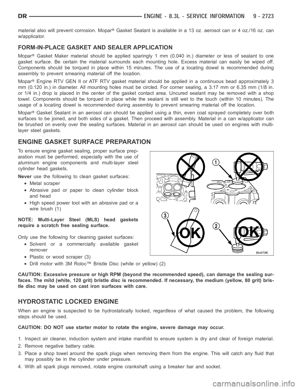
Neveruse the following to clean gasket surfaces:
Metal scraper
Abrasive pad or paper to clean cylinder block
and head
High speed power tool with an abrasive pad or a
wire brush (1)
NOTE: Multi-Layer Steel (MLS) head gaskets
require a scratch free sealing surface.
Only use the following for cleaning gasket surfaces:
Solvent or a commercially available gasket
remover
Plastic or wood scraper (3)
Drill motor with 3M Roloc™ Bristle Disc (white or yellow) (2)
CAUTION: Excessive pressure or high RPM (beyond the recommended speed), can damage the sealing sur-
faces. The mild (white, 120 grit) bristle disc is recommended. If necessary, the medium (yellow, 80 grit) bris-
tle disc may be used on cast iron surfaces with care.
HYDROSTATIC LOCKED ENGINE
When an engine is suspected to be hydrostatically locked, regardless of what caused the problem, the following
steps should be used.
CAUTION: DO NOT use starter motor to rotate the engine, severe damage may occur.
1. Inspect air cleaner, induction system and intake manifold to ensure system is dry and clear of foreign material.
2. Remove negative battery cable.
3. Place a shop towel around the spark plugs when removing them from the engine. This will catch any fluid that
may possibly be in the cylinder under pressure.
4. With all spark plugs removed, rotate engine crankshaft using a breaker bar and socket.
Page 2072 of 5267
SPRINGS/SEALS-VALVE
DIAGNOSIS AND TESTING
VA LV E S P R I N G T E S T I N G
The valve springs should be tested whenever
removed for inspection, reconditioning, or replace-
ment.
1. Obtain specifications for spring tension at specified
spring length (Refer to 9 - ENGINE - SPECIFICA-
TIONS).
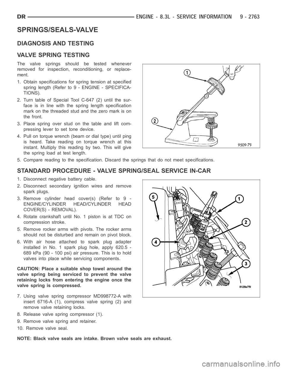
2. Turn table of Special Tool C-647 (2) until the sur-
face is in line with the spring length specification
mark on the threaded stud and the zero mark is on
the front.
3.Placespringoverstudonthetableandliftcom-
pressing lever to set tone device.
4. Pull on torque wrench (beam or dial type) until ping
is heard. Take reading on torque wrench at this
instant. Multiply this reading by two. This will give
the spring load at test length.
5. Compare reading to the specification. Discard the springs that do not meet specifications.
STANDARD PROCEDURE - VALVE SPRING/SEAL SERVICE IN-CAR
1. Disconnect negative battery cable.
2. Disconnect secondary ignition wires and remove
spark plugs.
3. Remove cylinder head cover(s) (Refer to 9 -
ENGINE/CYLINDER HEAD/CYLINDER HEAD
COVER(S) - REMOVAL).
4. Rotate crankshaft until No. 1 piston is at TDC on
compression stroke.
5. Remove rocker arms with pivots. The rocker arms
should not be disturbed and remain on pivot block.
6. With air hose attached to spark plug adapter
installed in No. 1 spark plug hole, apply 620.5 -
689 kPa (90 - 100 psi) air pressure. This is to hold
valves into place while servicing components.
CAUTION: Place a suitable shop towel around the
valve spring being serviced to prevent the valve
retaining locks from entering the engine once the
valve spring is compressed.
7. Using valve spring compressor MD998772-A with
insert 6716-A (1), compress valve spring (2) and
remove valve retaining locks.
8. Release valve spring compressor (1).
9. Remove valve spring and retainer.
10. Remove valve seal.
NOTE: Black valve seals are intake. Brown valve seals are exhaust.
Page 2087 of 5267
INSPECTION FOR REAR SEAL AREA LEAKS
Since it is sometimes difficult to determine the source of an oil leak in therear seal area of the engine, a more
involved inspection is necessary. The following steps should be followedto help pinpoint the source of the leak.
If the leakage occurs at the crankshaft rear oil seal area:
1. Disconnect the battery.
2. Raise the vehicle.
3. Remove torque converter or clutch housing cover and inspect rear of block for evidence of oil. Use a black light
to check for the oil leak:
a. Circular spray pattern generally indicates seal leakage or crankshaftdamage.
b. Where leakage tends to run straight down, possible causes are a porous block, distributor seal, camshaft
bore cup plugs oil galley pipe plugs, oil filter runoff, and main bearing cap to cylinder block mating surfaces.
4. If no leaks are detected, pressurize the crankcase as outlined in the, Inspection (Engine oil Leaks in general)
CAUTION: Do not exceed 20.6 kPa (3 psi).
5. If the leak is not detected, very slowly turn the crankshaft and watch forleakage. If a leak is detected between
the crankshaft and seal while slowly turning the crankshaft, it is possible the crankshaft seal surface is damaged.
The seal area on the crankshaft could have minor nicks or scratches that canbe polished out with emery cloth.
CAUTION: Use extreme caution when crankshaft polishing is necessary to remove minor nicks and
scratches. The crankshaft seal flange is especially machined to complement the function of the rear oil seal.
6. For bubbles that remain steady with shaft rotation, no further inspection can be done until disassembled.
Page 2203 of 5267
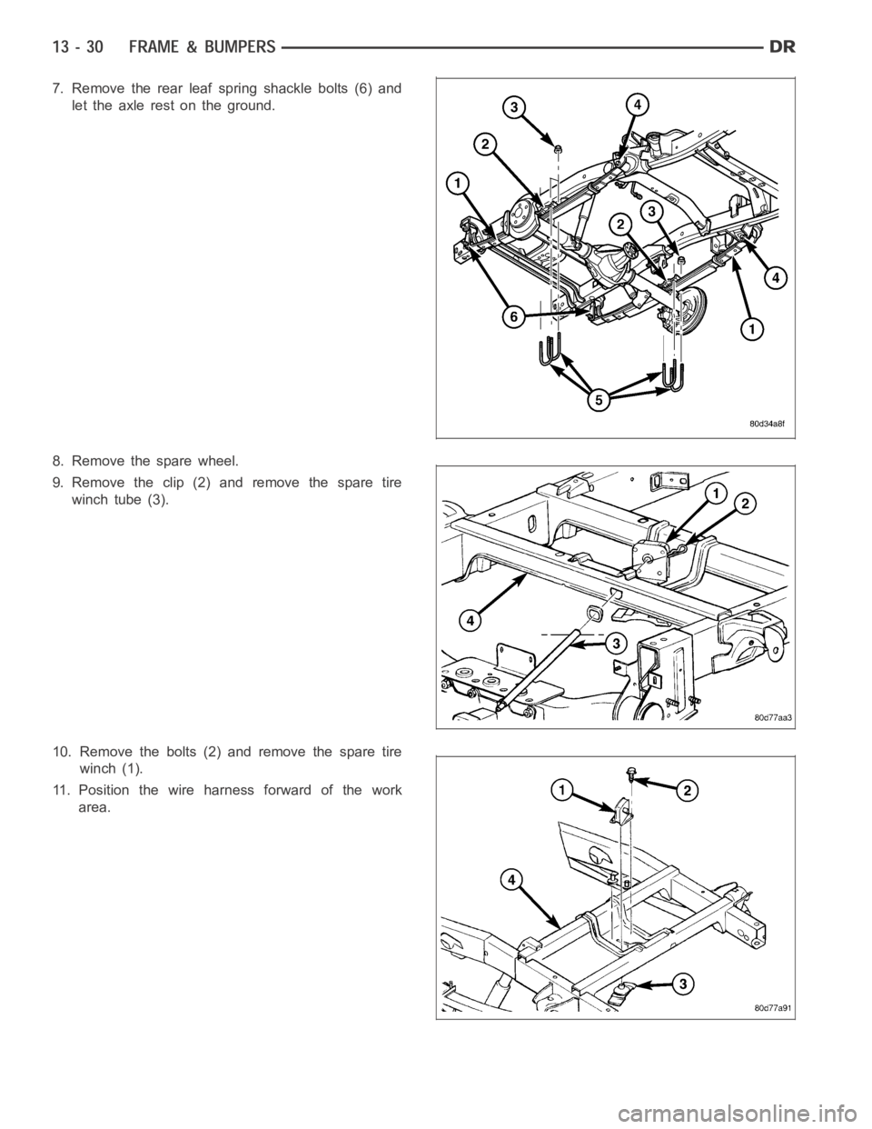
7. Remove the rear leaf spring shackle bolts (6) and
let the axle rest on the ground.
8. Remove the spare wheel.
9.Removetheclip(2)andremovethesparetire
winch tube (3).
10. Remove the bolts (2) and remove the spare tire
winch (1).
11. Position the wire harness forward of the work
area.
Page 2293 of 5267
INJECTOR - FUEL
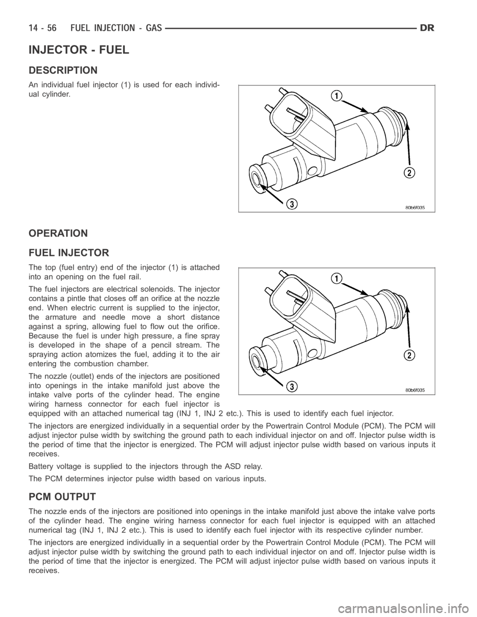
DESCRIPTION
An individual fuel injector (1) is used for each individ-
ual cylinder.
OPERATION
FUEL INJECTOR
The top (fuel entry) end of the injector (1) is attached
into an opening on the fuel rail.
The fuel injectors are electrical solenoids. The injector
contains a pintle that closes off an orifice at the nozzle
end. When electric current is supplied to the injector,
the armature and needle move a short distance
against a spring, allowing fuel to flow out the orifice.
Because the fuel is under high pressure, a fine spray
is developed in the shape of a pencil stream. The
spraying action atomizes the fuel, adding it to the air
entering the combustion chamber.
The nozzle (outlet) ends of the injectors are positioned
into openings in the intake manifold just above the
intake valve ports of the cylinder head. The engine
wiring harness connector for each fuel injector is
equipped with an attached numerical tag (INJ 1, INJ 2 etc.). This is used to identify each fuel injector.
The injectors are energized individually in a sequential order by the Powertrain Control Module (PCM). The PCM will
adjust injector pulse width by switching the ground path to each individual injector on and off. Injector pulse width is
the period of time that the injector isenergized. The PCM will adjust injector pulse width based on various inputs it
receives.
Battery voltage is supplied to the injectors through the ASD relay.
The PCM determines injector pulse width based on various inputs.
PCM OUTPUT
The nozzle ends of the injectors are positioned into openings in the intakemanifold just above the intake valve ports
of the cylinder head. The engine wiring harness connector for each fuel injector is equipped with an attached
numerical tag (INJ 1, INJ 2 etc.). This is used to identify each fuel injector with its respective cylinder number.
The injectors are energized individually in a sequential order by the Powertrain Control Module (PCM). The PCM will
adjust injector pulse width by switching the ground path to each individual injector on and off. Injector pulse width is
the period of time that the injector isenergized. The PCM will adjust injector pulse width based on various inputs it
receives.
Page 2315 of 5267
higher altitude, because the air density changes with altitude. It will also help to correct for varying barometric pres-
sure. Barometric pressure and altitude have a direct inverse correlation; as altitude goes up, barometric goes down.
At key-on, the PCM powers up and looks at MAP voltage, and based upon the voltage it sees, it knows the current
barometric pressure (relative to altitude). Once the engine starts, the PCM looks at the voltage again, continuously
every 12 milliseconds, and compares the current voltage to what it was at key-on. The difference between current
voltage and what it was at key-on, is manifold vacuum.
During key-on (engine not running) the sensor reads (updates) barometricpressure. A normal range can be
obtained by monitoring a known good sensor.
As the altitude increases, the air becomes thinner (less oxygen). If a vehicleisstartedanddriventoaverydifferent
altitude than where it was at key-on, the barometric pressure needs to be updated. Any time the PCM sees Wide
Open Throttle (WOT), based upon Throttle Position Sensor (TPS) angle and RPM, it will update barometric pressure
in the MAP memory cell. With periodic updates, the PCM can make its calculations more effectively.
The PCM uses the MAP sensor input to aid in calculating the following:
Manifold pressure
Barometric pressure
Engine load
Injector pulse-width
Spark-advance programs
Shift-point strategies (certain automatic transmissions only)
Idle speed
Decel fuel shutoff
The MAP sensor signal is provided from asingle piezoresistive element located in the center of a diaphragm. The
element and diaphragm are both made ofsilicone. As manifold pressure changes, the diaphragm moves causing
the element to deflect, which stresses the silicone. When silicone is exposed to stress, its resistance changes. As
manifold vacuum increases, the MAP sensor input voltage decreases proportionally. The sensor also contains elec-
tronics that condition the signal and provide temperature compensation.
The PCM recognizes a decrease in manifold pressure by monitoring a decrease in voltage from the reading stored
in the barometric pressure memory cell. The MAP sensor is a linear sensor; meaning as pressure changes, voltage
changes proportionately. The range of voltage output from the sensor is usually between 4.6 volts at sea level to as
low as 0.3 volts at 26 in. of Hg. Barometric pressure is the pressure exertedby the atmosphere upon an object. At
sea level on a standard day, no storm, barometric pressure is approximately 29.92 in Hg. For every 100 feet of
altitude, barometric pressure drops 0.10 in. Hg. If a storm goes through, it can change barometric pressure from
what should be present for that altitude. You should know what the average pressure and corresponding barometric
pressure is for your area.
Page 2336 of 5267
OPERATION
The 5.7L V-8 engine does not use a separate Throttle Position Sensor (TPS) on the throttle body.
The 3-wire TPS provides the Powertrain Control Module (PCM) with an input signal (voltage) that represents the
throttle blade position of the throttle body. The sensor is connected to the throttle blade shaft. As the position of the
throttle blade changes, the output voltage of the TPS changes.
The PCM supplies approximately 5 volts to the TPS. The TPS output voltage (input signal to the PCM) represents
the throttle blade position. The PCM receives an input signal voltage fromthe TPS. This will vary in an approximate
range of from .26 volts at minimum throttle opening (idle), to 4.49 volts atwide open throttle. Along with inputs from
other sensors, the PCM uses the TPS input to determine current engine operating conditions. In response to engine
operating conditions, the PCM will adjust fuel injector pulse width and ignition timing.
The PCM needs to identify the actions and position of the throttle blade at all times. This information is needed to
assist in performing the following calculations:
Ignition timing advance
Fuel injection pulse-width
Idle (learned value or minimum TPS)
Off-idle (0.06 volt)
Wide Open Throttle (WOT) open loop (2.608 volts above learned idle voltage)
Deceleration fuel lean out
Fuel cutoff during cranking at WOT (2.608 volts above learned idle voltage)
A/C WOT cutoff (certain automatic transmissions only)
REMOVAL
3.7L V6
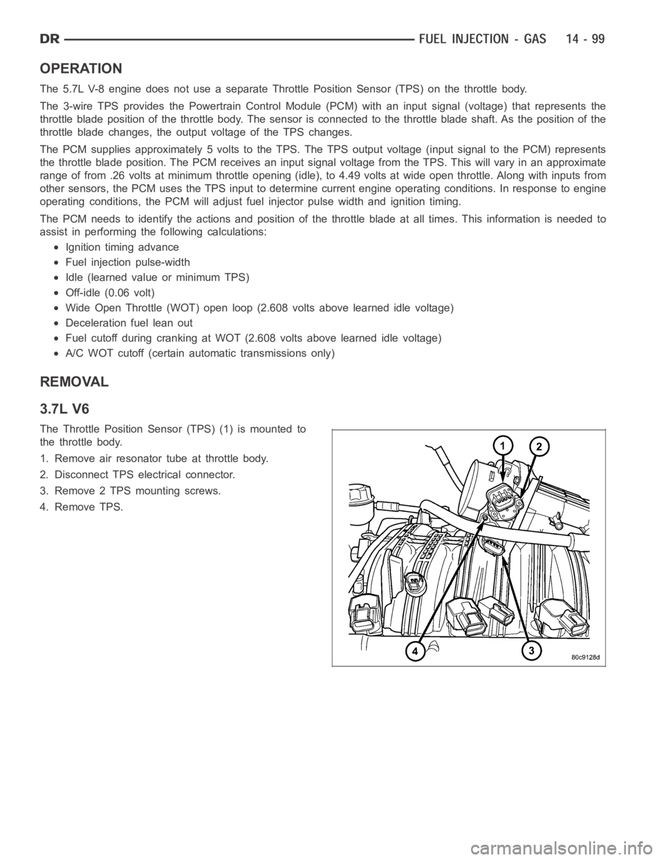
The Throttle Position Sensor (TPS) (1) is mounted to
the throttle body.
1. Remove air resonator tube at throttle body.
2. Disconnect TPS electrical connector.
3. Remove 2 TPS mounting screws.
4. Remove TPS.
Page 2343 of 5267
Fuel enters the system from the electric fuel transfer (lift) pump, which is located inside of the fuel tank and attached
to the fuel tank module (the fuel transfer pump is no longer attached to the engine). Fuel is forced through the fuel
filter element and then enters the Fuel Pump/Gear Pump, which is attached to the rear of the fuel injection pump.
The Fuel Pump/Gear Pump is a low-pressure pump and produce pressures ranging from 551.5 kpa (80 psi) to 1241
kpa (180) psi. Fuel then enters the fuel injection pump. Low pressure fuel is then supplied to the FCA (Fuel Control
Actuator).
The FCA is an electronically controlled solenoid valve. The ECM controls the amount of fuel that enters the high-
pressure pumping chambers by opening and closing the FCA based on a demanded fuel pressure. The FPS (Fuel
Pressure Sensor) on the fuel rail monitors the actual fuel pressure and provides it as an input to the ECM. When
the actuator is opened, the maximum amount of fuel is being supplied to the fuel injection pump. Any fuel that does
not enter the injection pump is directed to the overflow valve. The overflow valve regulates how much excess fuel
is used for lubrication of the pump and how much is returned to the tank through the drain manifold.
Fuel entering the injection pump is pressurized to between 300-1600 bar (4351-23,206 psi) by three radial pumping
chambers. The pressurized fuel is then supplied to the fuel rail.
STANDARD PROCEDURE
WATER DRAINING AT FUEL FILTER
Refer to Fuel Filter/Water Separatorremoval/installation for procedures.
CLEANING FUEL SYSTEM PARTS
CAUTION: Cleanliness cannot be overemphasized when handling or replacingdieselfuelsystemcompo-
nents. This especially includes the fuel injectors, high-pressure fuel lines and fuel injection pump. Very tight
tolerances are used with these parts. Dirt contamination could cause rapid part wear and possible plugging
of fuel injector nozzle tip holes. This in turn could lead to possible engine misfire. Always wash/clean any
fuel system component thoroughly before disassembly and then air dry. Capor cover any open part after
disassembly. Before assembly, examine each part for dirt, grease or othercontaminants and clean if nec-
essary. When installing new parts, lubricate them with clean engine oil orclean diesel fuel only.
FUEL SYSTEM PRIMING
A certain amount of air becomes trappedin the fuel system when fuel system components on the supply and/or
high-pressure side are serviced or replaced. Fuel system priming is accomplished using the electric fuel transfer (lift)
pump.
Servicing or replacing fuel system components will not require fuel systempriming.
The fuel transfer (lift) pump is self-priming: When the key is first turnedon (without cranking engine), the pump
operates for approximately 1 to 2 second and then shuts off (Note: When ambient temperatures are cold enough to
cause the intake air heaters to operate, the fuel lift pump will operate during the entire intake air pre-heat cycle).
The pump will also operate for up to 25 seconds after the starter is quickly engaged, and then disengaged without
allowing the engine to start. The pump shuts off immediately if the key is onand the engine stops running.
1. Turn key to CRANK position and quickly release key to ON position before engine starts. This will operate fuel
transfer pump for approximately 25 seconds.
2. Crank engine. If the engine does not start after 25 seconds, turn key to OFF position, and leave it off for at least
5 seconds. Repeat previous step until engine starts.
3. Fuel system priming is now completed.
4. Attempt to start engine. If engine will not start, proceed to following steps.When engine does start, it may run
erratically and be noisy for a few minutes. This is a normal condition.
CAUTION: Do not engage the starter motor for more than 30 seconds at a time. Allow two minutes between
cranking intervals.
5. Perform previous fuel priming procedure steps using fuel transfer pump. Be sure fuel is present at fuel tank.
6. Crank the engine for 30 seconds at a time to allow fuel system to prime.