2006 DODGE RAM SRT-10 ESP
[x] Cancel search: ESPPage 3012 of 5267
CLUTCHES-DRIVING
DESCRIPTION
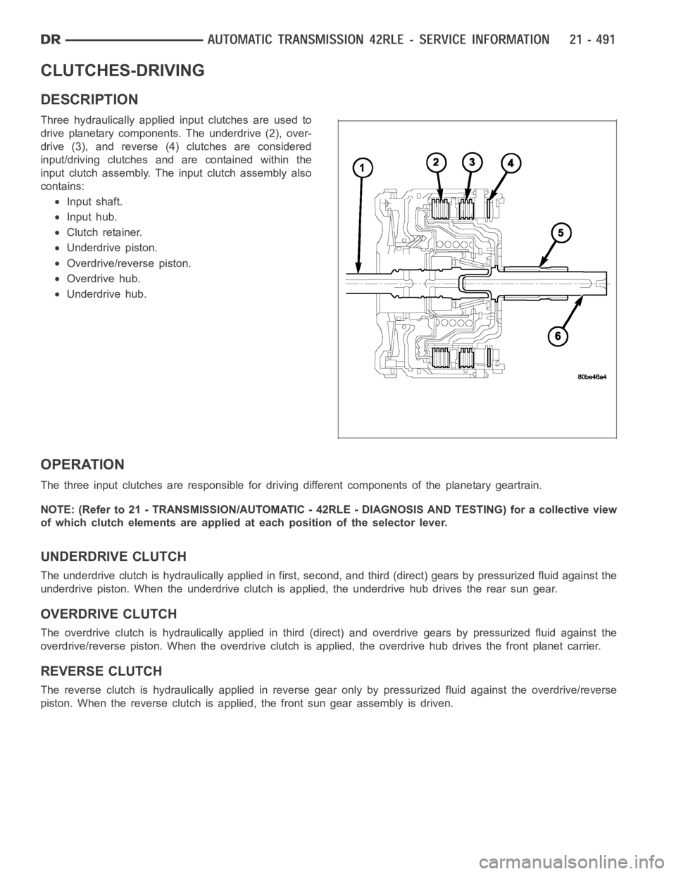
Three hydraulically applied input clutches are used to
drive planetary components. The underdrive (2), over-
drive (3), and reverse (4) clutches are considered
input/driving clutches and are contained within the
input clutch assembly. The input clutch assembly also
contains:
Input shaft.
Input hub.
Clutch retainer.
Underdrive piston.
Overdrive/reverse piston.
Overdrive hub.
Underdrive hub.
OPERATION
The three input clutches are responsible for driving different components of the planetary geartrain.
NOTE: (Refer to 21 - TRANSMISSION/AUTOMATIC - 42RLE - DIAGNOSIS AND TESTING) for a collective view
ofwhichclutchelementsareappliedateachpositionoftheselectorlever.
UNDERDRIVE CLUTCH
The underdrive clutch is hydraulically applied in first, second, and third (direct) gears by pressurized fluid against the
underdrive piston. When the underdrive clutch is applied, the underdrivehub drives the rear sun gear.
OVERDRIVE CLUTCH
The overdrive clutch is hydraulically applied in third (direct) and overdrive gears by pressurized fluid against the
overdrive/reverse piston. When the overdrive clutch is applied, the overdrive hub drives the front planet carrier.
REVERSE CLUTCH
The reverse clutch is hydraulically applied in reverse gear only by pressurized fluid against the overdrive/reverse
piston. When the reverse clutch is applied, the front sun gear assembly is driven.
Page 3058 of 5267
SOLENOID
DESCRIPTION
The typical electrical solenoid used in automotive applications is a linear actuator. It is a device that produces
motion in a straight line. This straight line motion can be either forward or backward in direction, and short or long
distance.
A solenoid is an electromechanical device that uses a magnetic force to perform work. It consists of a coil of wire,
wrapped around a magnetic core made from steel or iron, and a spring loaded,movable plunger, which performs
the work, or straight line motion.
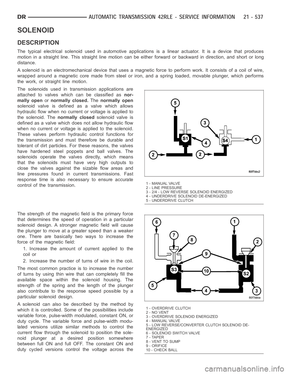
The solenoids used in transmission applications are
attached to valves which can be classified asnor-
mally openornormally closed.Thenormally open
solenoid valve is defined as a valve which allows
hydraulic flow when no current or voltage is applied to
the solenoid. Thenormally closedsolenoid valve is
defined as a valve which does not allow hydraulic flow
when no current or voltage is applied to the solenoid.
These valves perform hydraulic control functions for
the transmission and must therefore be durable and
tolerant of dirt particles. For these reasons, the valves
have hardened steel poppets and ball valves. The
solenoids operate the valves directly, which means
that the solenoids must have very high outputs to
close the valves against the sizable flow areas and
line pressures found in current transmissions. Fast
response time is also necessary to ensure accurate
control of the transmission.
The strength of the magnetic field is the primary force
that determines the speed of operation in a particular
solenoid design. A stronger magnetic field will cause
the plunger to move at a greater speed than a weaker
one. There are basically two ways to increase the
force of the magnetic field:
1. Increase the amount of current applied to the
coil or
2. Increase the number of turns of wire in the coil.
The most common practice is to increase the number
of turns by using thin wire that can completely fill the
available space within the solenoid housing. The
strength of the spring and the length of the plunger
also contribute to the response speed possible by a
particular solenoid design.
A solenoid can also be described by the method by
which it is controlled. Some of the possibilities include
variable force, pulse-width modulated, constant ON, or
duty cycle. The variable force and pulse-width modu-
lated versions utilize similar methods to control the
current flow through the solenoid to position the sole-
noid plunger at a desired position somewhere
between full ON and full OFF. The constant ON and
duty cycled versions control the voltage across the
1 - MANUAL VALVE
2 - LINE PRESSURE
3 - 2/4 - LOW REVERSE SOLENOID ENERGIZED
4 - UNDERDRIVE SOLENOID DE-ENERGIZED
5 - UNDERDRIVE CLUTCH
1-OVERDRIVECLUTCH
2 - NO VENT
3 - OVERDRIVE SOLENOID ENERGIZED
4 - MANUAL VALVE
5 - LOW REVERSE/CONVERTER CLUTCH SOLENOID DE-
ENERGIZED
6-SOLENOIDSWITCHVALVE
7 - TAPER
8 - VENT TO SUMP
9 - ORIFICE
10 - CHECK BALL
Page 3061 of 5267
GEAR L/R 2/4 OD
ROPOPOP
P/N CL OP OP
1st CL OP OP
2nd OP CL OP
DOPOPCL
OD OP CL CL
OP = OPEN
CL = CLOSED
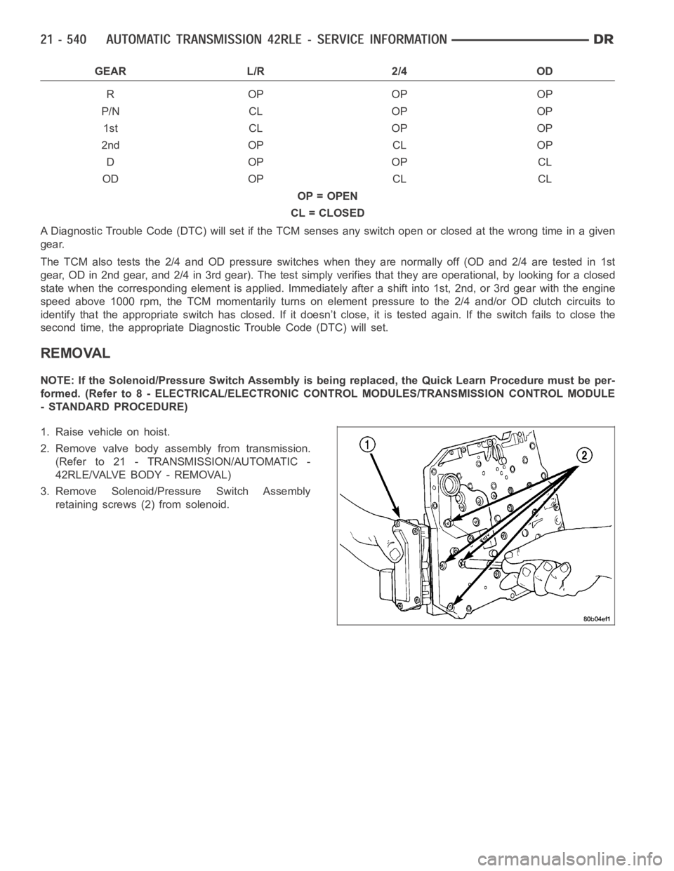
A Diagnostic Trouble Code (DTC) will set if the TCM senses any switch open orclosed at the wrong time in a given
gear.
The TCM also tests the 2/4 and OD pressure switches when they are normally off (OD and 2/4 are tested in 1st
gear, OD in 2nd gear, and 2/4 in 3rd gear). The test simply verifies that theyare operational, by looking for a closed
state when the corresponding elementis applied. Immediately after a shift into 1st, 2nd, or 3rd gear with the engine
speed above 1000 rpm, the TCM momentarily turns on element pressure to the 2/4 and/or OD clutch circuits to
identify that the appropriate switch has closed. If it doesn’t close, it istested again. If the switch fails to close the
second time, the appropriate Diagnostic Trouble Code (DTC) will set.
REMOVAL
NOTE: If the Solenoid/Pressure Switch Assembly is being replaced, the Quick Learn Procedure must be per-
formed. (Refer to 8 - ELECTRICAL/ELECTRONIC CONTROL MODULES/TRANSMISSION CONTROL MODULE
- STANDARD PROCEDURE)
1. Raise vehicle on hoist.
2. Remove valve body assembly from transmission.
(Refer to 21 - TRANSMISSION/AUTOMATIC -
42RLE/VALVE BODY - REMOVAL)
3. Remove Solenoid/Pressure Switch Assembly
retaining screws (2) from solenoid.
Page 3082 of 5267
MANUAL VALVE
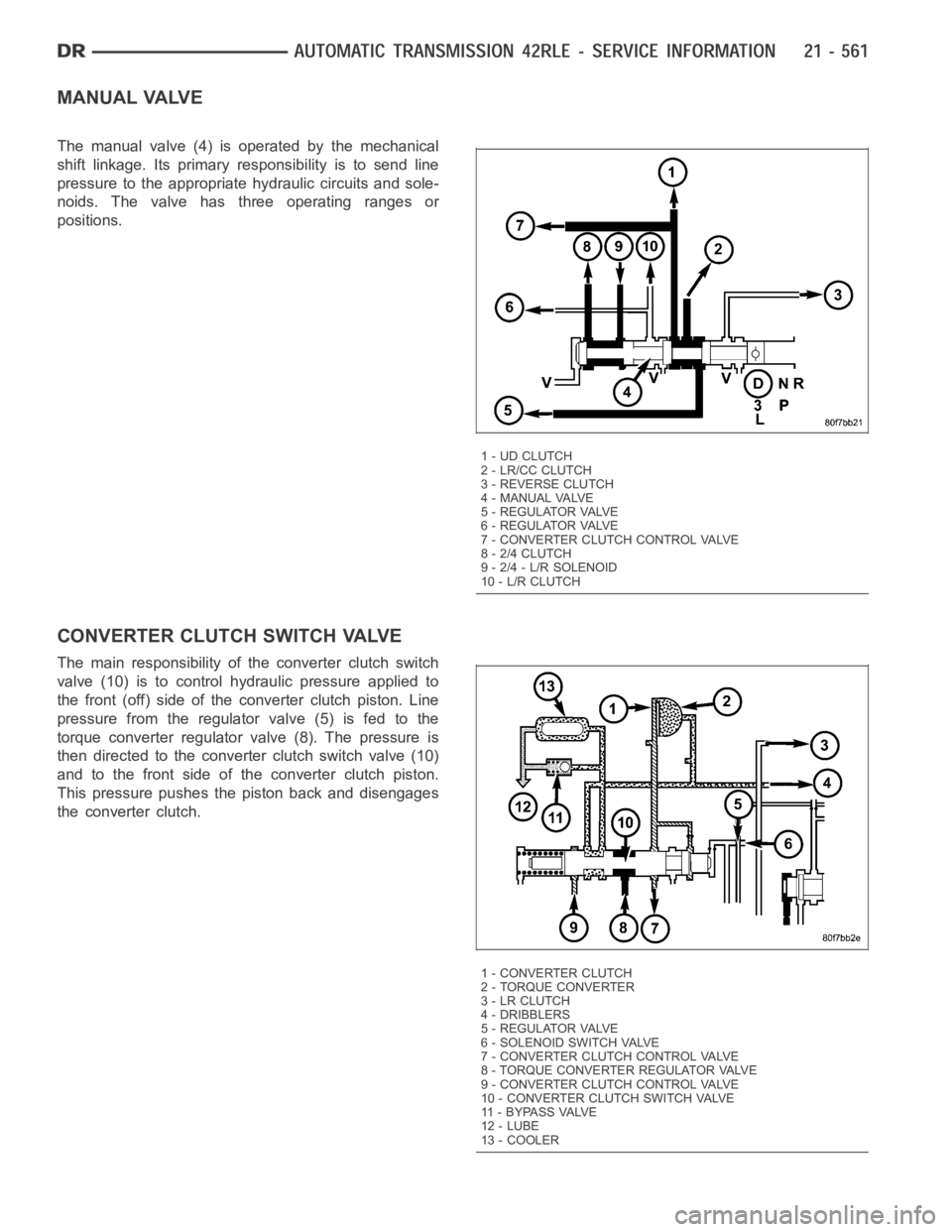
The manual valve (4) is operated by the mechanical
shift linkage. Its primary responsibility is to send line
pressure to the appropriate hydraulic circuits and sole-
noids. The valve has three operating ranges or
positions.
CONVERTER CLUTCH SWITCH VALVE
The main responsibility of the converter clutch switch
valve (10) is to control hydraulic pressure applied to
the front (off) side of the converter clutch piston. Line
pressure from the regulator valve (5) is fed to the
torque converter regulator valve (8). The pressure is
then directed to the converter clutch switch valve (10)
and to the front side of the converter clutch piston.
This pressure pushes the piston back and disengages
the converter clutch.
1 - UD CLUTCH
2 - LR/CC CLUTCH
3 - REVERSE CLUTCH
4 - MANUAL VALVE
5 - REGULATOR VALVE
6 - REGULATOR VALVE
7 - CONVERTER CLUTCH CONTROL VALVE
8 - 2/4 CLUTCH
9 - 2/4 - L/R SOLENOID
10 - L/R CLUTCH
1 - CONVERTER CLUTCH
2 - TORQUE CONVERTER
3 - LR CLUTCH
4 - DRIBBLERS
5 - REGULATOR VALVE
6-SOLENOIDSWITCHVALVE
7 - CONVERTER CLUTCH CONTROL VALVE
8 - TORQUE CONVERTER REGULATOR VALVE
9 - CONVERTER CLUTCH CONTROL VALVE
10 - CONVERTER CLUTCH SWITCH VALVE
11 - B Y PA S S VA LV E
12 - LUBE
13 - COOLER
Page 3136 of 5267
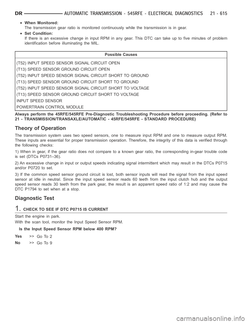
When Monitored:
The transmission gear ratio is monitored continuously while the transmission is in gear.
Set Condition:
IfthereisanexcessivechangeininputRPMinanygear.ThisDTCcantakeupto five minutes of problem
identification beforeilluminating the MIL.
Possible Causes
(T52) INPUT SPEED SENSOR SIGNAL CIRCUIT OPEN
(T13) SPEED SENSOR GROUND CIRCUIT OPEN
(T52) INPUT SPEED SENSOR SIGNAL CIRCUIT SHORT TO GROUND
(T13) SPEED SENSOR GROUND CIRCUIT SHORT TO GROUND
(T52) INPUT SPEED SENSOR SIGNAL CIRCUIT SHORT TO VOLTAGE
(T13) SPEED SENSOR GROUND CIRCUIT SHORT TO VOLTAGE
INPUT SPEED SENSOR
POWERTRAIN CONTROL MODULE
Always perform the 45RFE/545RFE Pre-Diagnostic Troubleshooting Procedure before proceeding. (Refer to
21 - TRANSMISSION/TRANSAXLE/AUTOMATIC - 45RFE/545RFE - STANDARD PROCEDURE)
Theory of Operation
The transmission system uses two speed sensors, one to measure input RPM and one to measure output RPM.
These inputs are essential for proper transmission operation. Therefore, the integrity of this data is verified through
the following checks:
1) When in gear, if the gear ratio does not compare to a known gear ratio, the corresponding in-gear trouble code
is set (DTCs P0731–36).
2) An excessive change in input or output speeds indicating signal intermittent which may result in the DTCs P0715
and/or P0720 to set.
3) If the common speed sensor ground circuit is lost, both sensor inputs will read the signal from the input speed
sensor at idle in neutral. Since the input speed sensor reads 60 teeth from the input clutch hub and the output
speed sensor reads 30 teeth from the park gear, the result is an apparent speed ratio of 1:2 and may cause the
DTC P1794 to set when at a stop.
Diagnostic Test
1.CHECK TO SEE IF DTC P0715 IS CURRENT
Start the engine in park.
With the scan tool, monitor the Input Speed Sensor RPM.
Is the Input Speed Sensor RPM below 400 RPM?
Ye s>>
Go To 2
No>>
Go To 9
Page 3142 of 5267
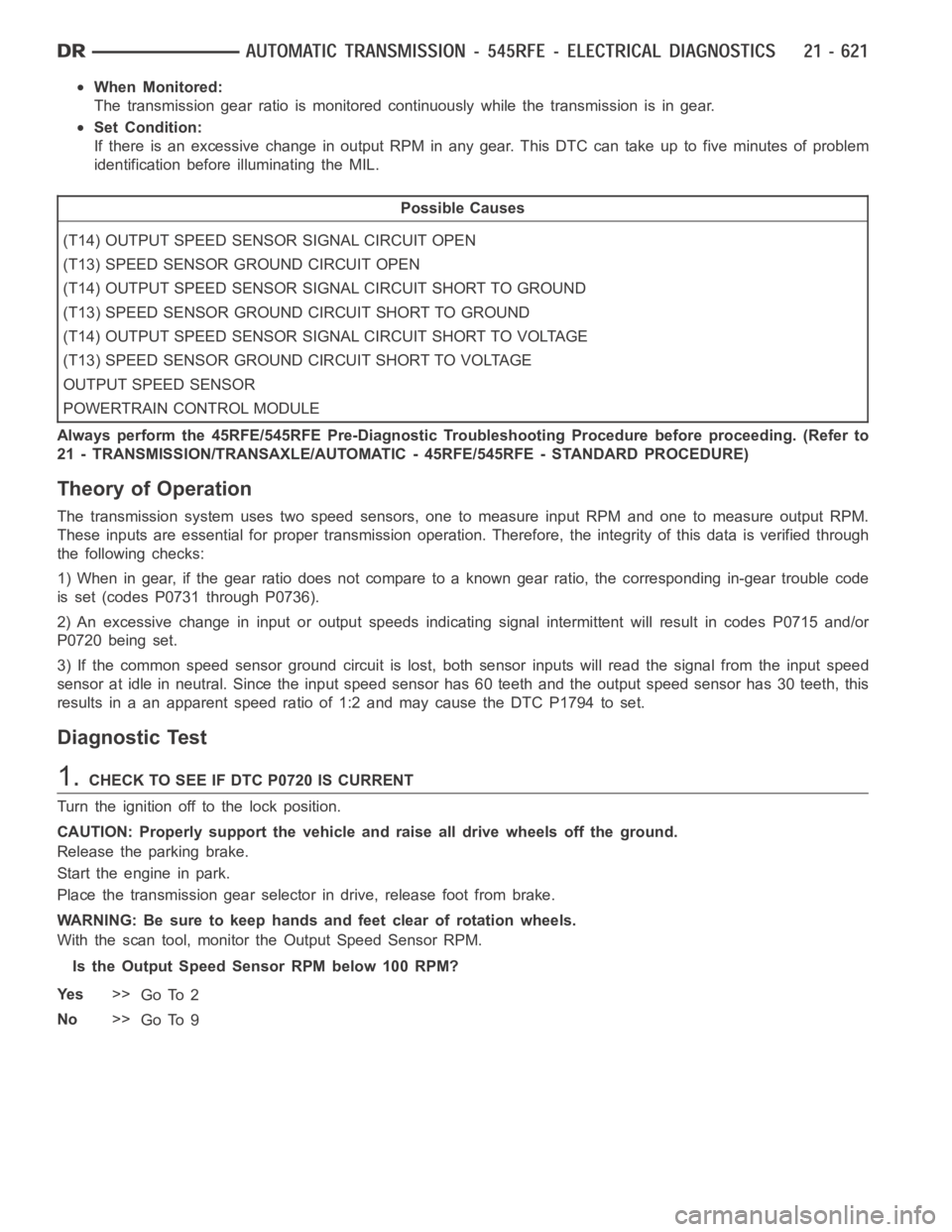
When Monitored:
The transmission gear ratio is monitored continuously while the transmission is in gear.
Set Condition:
If there is an excessive change in output RPM in any gear. This DTC can take upto five minutes of problem
identification beforeilluminating the MIL.
Possible Causes
(T14) OUTPUT SPEED SENSOR SIGNAL CIRCUIT OPEN
(T13) SPEED SENSOR GROUND CIRCUIT OPEN
(T14) OUTPUT SPEED SENSOR SIGNAL CIRCUIT SHORT TO GROUND
(T13) SPEED SENSOR GROUND CIRCUIT SHORT TO GROUND
(T14) OUTPUT SPEED SENSOR SIGNAL CIRCUIT SHORT TO VOLTAGE
(T13) SPEED SENSOR GROUND CIRCUIT SHORT TO VOLTAGE
OUTPUT SPEED SENSOR
POWERTRAIN CONTROL MODULE
Always perform the 45RFE/545RFE Pre-Diagnostic Troubleshooting Procedure before proceeding. (Refer to
21 - TRANSMISSION/TRANSAXLE/AUTOMATIC - 45RFE/545RFE - STANDARD PROCEDURE)
Theory of Operation
The transmission system uses two speed sensors, one to measure input RPM and one to measure output RPM.
These inputs are essential for proper transmission operation. Therefore, the integrity of this data is verified through
the following checks:
1) When in gear, if the gear ratio does not compare to a known gear ratio, the corresponding in-gear trouble code
is set (codes P0731 through P0736).
2) An excessive change in input or output speeds indicating signal intermittent will result in codes P0715 and/or
P0720 being set.
3) If the common speed sensor ground circuit is lost, both sensor inputs will read the signal from the input speed
sensor at idle in neutral. Since the input speed sensor has 60 teeth and the output speed sensor has 30 teeth, this
results in a an apparent speed ratio of 1:2 and may cause the DTC P1794 to set.
Diagnostic Test
1.CHECK TO SEE IF DTC P0720 IS CURRENT
Turn the ignition off to the lock position.
CAUTION: Properly support the vehicle and raise all drive wheels off the ground.
Release the parking brake.
Start the engine in park.
Place the transmission gear selector in drive, release foot from brake.
WARNING: Be sure to keep hands and feet clear of rotation wheels.
With the scan tool, monitor the Output Speed Sensor RPM.
Is the Output Speed Sensor RPM below 100 RPM?
Ye s>>
Go To 2
No>>
Go To 9
Page 3149 of 5267
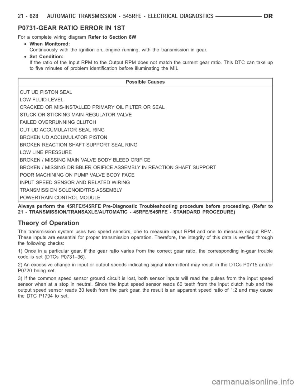
P0731-GEAR RATIO ERROR IN 1ST
For a complete wiring diagramRefer to Section 8W
When Monitored:
Continuously with the ignition on, engine running, with the transmissionin gear.
Set Condition:
If the ratio of the Input RPM to the Output RPM does not match the current gearratio. This DTC can take up
to five minutes of problem identification before illuminating the MIL
Possible Causes
CUT UD PISTON SEAL
LOW FLUID LEVEL
CRACKED OR MIS-INSTALLED PRIMARY OIL FILTER OR SEAL
STUCK OR STICKING MAIN REGULATOR VALVE
FAILED OVERRUNNING CLUTCH
CUT UD ACCUMULATOR SEAL RING
BROKEN UD ACCUMULATOR PISTON
BROKEN REACTION SHAFT SUPPORT SEAL RING
LOW LINE PRESSURE
BROKEN / MISSING MAIN VALVE BODY BLEED ORIFICE
BROKEN / MISSING DRIBBLER ORIFICE ASSEMBLY IN REACTION SHAFT SUPPORT
POOR MACHINING ON PUMP VALVE BODY FACE
INPUT SPEED SENSOR AND RELATED WIRING
TRANSMISSION SOLENOID/TRS ASSEMBLY
POWERTRAIN CONTROL MODULE
Always perform the 45RFE/545RFE Pre-Diagnostic Troubleshooting procedure before proceeding. (Refer to
21 - TRANSMISSION/TRANSAXLE/AUTOMATIC - 45RFE/545RFE - STANDARD PROCEDURE)
Theory of Operation
The transmission system uses two speed sensors, one to measure input RPM and one to measure output RPM.
These inputs are essential for proper transmission operation. Therefore, the integrity of this data is verified through
the following checks:
1) Once in a particular gear, if the gear ratio varies from the correct gear ratio, the corresponding in-gear trouble
code is set (DTCs P0731–36).
2) An excessive change in input or output speeds indicating signal intermittent may result in the DTCs P0715 and/or
P0720 being set.
3) If the common speed sensor ground circuit is lost, both sensor inputs will read the pulses from the input speed
sensor when at a stop in neutral. Since the input speed sensor reads 60 teethfrom the input clutch hub and the
output speed sensor reads 30 teeth from the park gear, the result is an apparent speed ratio of 1:2 and may cause
the DTC P1794 to set.
Page 3150 of 5267
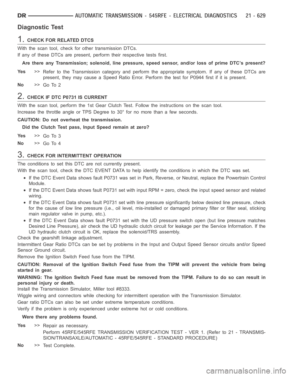
Diagnostic Test
1.CHECKFORRELATEDDTCS
With the scan tool, check for other transmission DTCs.
If any of these DTCs are present, perform their respective tests first.
Are there any Transmission; solenoid, line pressure, speed sensor, and/or loss of prime DTC’s present?
Ye s>>
Refer to the Transmission category and perform the appropriate symptom. If any of these DTCs are
present, they may cause a Speed Ratio Error. Perform the test for P0944 firstifitispresent.
No>>
Go To 2
2.CHECK IF DTC P0731 IS CURRENT
With the scan tool, perform the 1st Gear Clutch Test. Follow the instructions on the scan tool.
Increase the throttle angle or TPS Degree to 30° for no more than a few seconds.
CAUTION: Do not overheat the transmission.
Did the Clutch Test pass, Input Speed remain at zero?
Ye s>>
Go To 3
No>>
Go To 4
3.CHECK FOR INTERMITTENT OPERATION
The conditions to set this DTC are not currently present.
With the scan tool, check the DTC EVENT DATA to help identify the conditionsin which the DTC was set.
If the DTC Event Data shows fault P0731 was set in Park, Reverse, or Neutral,replace the Powertrain Control
Module.
If the DTC Event Data shows fault P0731 set with input RPM = zero, check the input speed sensor and related
wiring.
If the DTC Event Data shows fault P0731 set with line pressure significantly below desired line pressure, check
for the cause of low line pressure (i.e., oil level, mis-installed or damaged primary filter or filter seal, sticking
main regulator valve in pump, etc.).
If the DTC Event Data shows fault P0731 set with the UD pressure switch open (but line pressure matches
Desired Line Pressure), air check the UD hydraulic clutch circuit for leakage per the Service Information. If the
UD hydraulic clutch circuit is OK, replace the solenoid/TRS assembly.
Check the gearshift linkage adjustment.
Intermittent Gear Ratio DTCs can be set by problems in the Input and Output Speed Sensor circuits and/or Speed
Sensor Ground circuit.
Remove the Ignition Switch Feed fuse from the TIPM.
CAUTION: Removal of the Ignition Switch Feed fuse from the TIPM will prevent the vehicle from being
startedingear.
WARNING: The Ignition Switch Feed fuse must be removed from the TIPM. Failure to do so can result in
personal injury or death.
Install the Transmission Simulator, Miller tool #8333.
Wiggle wiring and connectors while checking for intermittent operation with the Transmission Simulator.
Gear ratio DTCs can also be set under extreme temperature conditions.
Verify if the problem is only experienced under extreme hot or cold conditions.
Were there any problems found.
Ye s>>
Repair as necessary.
Perform 45RFE/545RFE TRANSMISSION VERIFICATION TEST - VER 1. (Refer to 21- TRANSMIS-
SION/TRANSAXLE/AUTOMATIC - 45RFE/545RFE - STANDARD PROCEDURE)
No>>
Te s t C o m p l e t e .