2006 DODGE RAM SRT-10 ESP
[x] Cancel search: ESPPage 3181 of 5267
When Monitored:
Initially at power-up, then every 10 seconds thereafter. The solenoid circuits will also be tested immediately
after a gear ratio or pressure switch error is detected.
Set Condition:
After three consecutive solenoid continuity test failures, or one failure if test is run in response to a gear ratio
or pressure switch error.Note: This DTC is strictly an electrical fault and does not apply to any internal
transmission failures.
Possible Causes
RELATED TIPM TCM DTCS PRESENT
(T219) 2C SOLENOID CONTROL CIRCUIT SHORT TO OTHER CIRCUITS
(T219) 2C SOLENOID CONTROL CIRCUIT OPEN
(T219) 2C SOLENOID CONTROL CIRCUIT SHORT TO GROUND
TRANSMISSION SOLENOID/TRS ASSEMBLY
POWERTRAIN CONTROL MODULE
Always perform the 45RFE/545RFE Pre-Diagnostic Troubleshooting Procedure before proceeding. (Refer to
21 - TRANSMISSION/TRANSAXLE/AUTOMATIC - 45RFE/545RFE - STANDARD PROCEDURE)
Theory of Operation
The Transmission Control System uses six electronically controlled solenoids that allow hydraulic fluid to be applied
to various friction elements (clutches), which enables the gear requested. The continuity of each solenoid circuit is
periodically tested. Each inactive solenoid is turned on for a few milliseconds, then off. Each active solenoid is
turned off for a few milliseconds, then on. This pulsing of voltage to the solenoid causes an inductive spike which
can be sensed by the Transmission Control System. If an inductive spike is not sensed by the Transmission Control
System during the continuity check, it is tested again. If the test fails three consecutive times, the appropriate Diag-
nostic Trouble Code (DTC) is set. If the solenoid test is run in response to agear ratio or pressure switch error, one
failure will result in setting the appropriate DTC.Note: This DTC is strictly an electrical fault and does not apply
to any internal transmission failures.
Diagnostic Test
1.CHECK FOR TCM TIPM DTCS
With the scan tool under TIPM, check for TCM Power Input DTCs.
Are there any TIPM TCM Power Input DTCs present?
Ye s>>
Refer to the Transmission category and perform the appropriate symptom.
No>>
Go To 2
2.CHECK TO SEE IF P0755 IS PRESENT
Turn the ignition off to the lock position.
Remove the Ignition Switch Feed fuse from the TIPM.
CAUTION: Removal of the Ignition Switch Feed fuse from the TIPM will prevent the vehicle from being
startedingear.
WARNING: The Ignition Switch Feed fuse must be removed from the TIPM. Failure to do so can result in
personal injury or death.
Install the Transmission Simulator, Miller tool #8333.
Ignition on, engine not running.
With the scan tool, actuate the 2C Solenoid.
Did the 2C Solenoid LED blink on and off on the Transmission Simulator?
Ye s>>
Go To 3
No>>
Go To 4
Page 3185 of 5267
When Monitored:
Initially at power-up, then every 10 seconds thereafter. The solenoid circuits will also be tested immediately
after a gear ratio or pressure switch error is detected.
Set Condition:
After three consecutive solenoid continuity test failures, or one failure if test is run in response to a gear ratio
or pressure switch error.Note: This DTC is strictly an electrical fault and does not apply to any internal
transmission failures.
Possible Causes
RELATED TIPM TCM DTCS PRESENT
(T60) OD SOLENOID CONTROL CIRCUIT SHORT TO OTHER CIRCUITS
(T60) OD SOLENOID CONTROL CIRCUIT OPEN
(T60) OD SOLENOID CONTROL CIRCUIT SHORT TO GROUND
TRANSMISSION SOLENOID/TRS ASSEMBLY
POWERTRAIN CONTROL MODULE
Always perform the 45RFE/545RFE Pre-Diagnostic Troubleshooting Procedure before proceeding. (Refer to
21 - TRANSMISSION/TRANSAXLE/AUTOMATIC - 45RFE/545RFE - STANDARD PROCEDURE)
Theory of Operation
The Transmission Control System uses six electronically controlled solenoids that allow hydraulic fluid to be applied
to various friction elements (clutches), which enables the gear requested. The continuity of each solenoid circuit is
periodically tested. Each inactive solenoid is turned on for a few milliseconds, then off. Each active solenoid is
turned off for a few milliseconds, then on. This pulsing of voltage to the solenoid causes an inductive spike which
can be sensed by the Transmission Control System. If an inductive spike is not sensed by the Transmission Control
System during the continuity check, it is tested again. If the test fails three consecutive times, the appropriate Diag-
nostic Trouble Code (DTC) is set. If the solenoid test is run in response to agear ratio or pressure switch error, one
failure will result in setting the appropriate DTC.Note: This DTC is strictly an electrical fault and does not apply
to any internal transmission failures.
Diagnostic Test
1.RELATED TIPM TCM DTCS PRESENT
With the scan tool, check for TIPM DTCs.
Are there any TIPM TCM DTCs present?
Ye s>>
Refer to the Transmission category and perform the appropriate symptom.
No>>
Go To 2
2.CHECK TO SEE IF P0760 IS PRESENT
Turn the ignition off to the lock position.
Remove the Ignition Switch Feed fuse from the TIPM.
CAUTION: Removal of the Ignition Switch Feed fuse from the TIPM will prevent the vehicle from being
startedingear.
WARNING: The Ignition Switch Feed fuse must be removed from the TIPM. Failure to do so can result in
personal injury or death.
Install Transmission Simulator, Miller tool #8333.
Ignition on, engine not running.
With the scan tool, actuate the OD Solenoid.
Page 3189 of 5267
When Monitored:
Initially at power-up, then every 10 seconds thereafter. The solenoid circuits will also be tested immediately
after a gear ratio or pressure switch error is detected.
Set Condition:
After three consecutive solenoid continuity test failures, or one failure if test is run in response to a gear ratio
or pressure switch error.Note: This DTC is strictly an electrical fault and does not apply to any internal
transmission failures.
Possible Causes
RELATED TIPM TCM DTCS PRESENT
(T59) UD SOLENOID CONTROL CIRCUIT SHORT TO OTHER CIRCUITS
(T59) UD SOLENOID CONTROL CIRCUIT OPEN
(T59) UD SOLENOID CONTROL CIRCUIT SHORT TO GROUND
TRANSMISSION SOLENOID/TRS ASSEMBLY
POWERTRAIN CONTROL MODULE
Always perform the 45RFE/545RFE Pre-Diagnostic Troubleshooting Procedure before proceeding. (Refer to
21 - TRANSMISSION/TRANSAXLE/AUTOMATIC - 45RFE/545RFE - STANDARD PROCEDURE)
Theory of Operation
The Transmission Control System uses six electronically controlled solenoids that allow hydraulic fluid to be applied
to various friction elements (clutches), which enables the gear requested. The continuity of each solenoid circuit is
periodically tested. Each inactive solenoid is turned on for a few milliseconds, then off. Each active solenoid is
turned off for a few milliseconds, then on. This pulsing of voltage to the solenoid causes an inductive spike which
can be sensed by the Transmission Control System. If an inductive spike is not sensed by the Transmission Control
System during the continuity check, it is tested again. If the test fails three consecutive times, the appropriate Diag-
nostic Trouble Code (DTC) is set. If the solenoid test is run in response to agear ratio or pressure switch error, one
failure will result in setting the appropriate DTC.Note: This DTC is strictly an electrical fault and does not apply
to any internal transmission failures.
Diagnostic Test
1.CHECK FOR TCM TIPM DTCS
With the scan tool under TIPM, check for TCM Power Input DTCs.
Are there any TIPM TCM Power Input DTCs present?
Ye s>>
Refer to the Transmission category and perform the appropriate symptom.
No>>
Go To 2
2.CHECK IF P0765 IS PRESENT
Turn the ignition off to the lock position.
Remove the Ignition Switch Feed fuse from the TIPM.
CAUTION: Removal of the Ignition Switch Feed fuse from the TIPM will prevent the vehicle from being
startedingear.
WARNING: The Ignition Switch Feed fuse must be removed from the TIPM. Failure to do so can result in
personal injury or death.
Install Transmission Simulator, Miller tool #8333.
Ignition on, engine not running.
With the scan tool, actuate the UD Solenoid.
Page 3193 of 5267
When Monitored:
Initially at power-up, then every 10 seconds thereafter. The solenoid circuits will also be tested immediately
after a gear ratio or pressure switch error is detected.
Set Condition:
After three consecutive solenoid continuity test failures, or one failure if test is run in response to a gear ratio
or pressure switch error.Note: This DTC is strictly an electrical fault and does not apply to any internal
transmission failures.
Possible Causes
RELATED TIPM TCM DTCS PRESENT
(T259) 4C SOLENOID CONTROL CIRCUIT SHORT TO OTHER CIRCUITS
(T259) 4C SOLENOID CONTROL CIRCUIT OPEN
(T259) 4C SOLENOID CONTROL CIRCUIT SHORT TO GROUND
TRANSMISSION SOLENOID/TRS ASSEMBLY
POWERTRAIN CONTROL MODULE
Always perform the 45RFE/545RFE Pre-Diagnostic Troubleshooting Procedure before proceeding. (Refer to
21 - TRANSMISSION/TRANSAXLE/AUTOMATIC - 45RFE/545RFE - STANDARD PROCEDURE)
Theory of Operation
The Transmission Control System uses six electronically controlled solenoids that allow hydraulic fluid to be applied
to various friction elements (clutches), which enables the gear requested. The continuity of each solenoid circuit is
periodically tested. Each inactive solenoid is turned on for a few milliseconds, then off. Each active solenoid is
turned off for a few milliseconds, then on. This pulsing of voltage to the solenoid causes an inductive spike which
can be sensed by the Transmission Control System. If an inductive spike is not sensed by the Transmission Control
System during the continuity check, it is tested again. If the test fails three consecutive times, the appropriate Diag-
nostic Trouble Code (DTC) is set. If the solenoid test is run in response to agear ratio or pressure switch error, one
failure will result in setting the appropriate DTC.Note: This DTC is strictly an electrical fault and does not apply
to any internal transmission failures.
Diagnostic Test
1.CHECK FOR TCM TIPM DTCS
With the scan tool under TIPM, check for TCM Power Input DTCs.
Are there any TIPM TCM Power Input DTCs present?
Ye s>>
Refer to the Transmission category and perform the appropriate symptom.
No>>
Go To 2
2.CHECK TO SEE IF P0770 IS PRESENT
Turn the ignition off to the lock position.
Remove the Ignition Switch Feed fuse from the TIPM.
CAUTION: Removal of the Ignition Switch Feed fuse from the TIPM will prevent the vehicle from being
startedingear.
WARNING: The Ignition Switch Feed fuse must be removed from the TIPM. Failure to do so can result in
personal injury or death.
Install Transmission Simulator, Miller tool #8333.
Ignition on, engine not running.
With the scan tool, actuate the 4C Solenoid.
Page 3197 of 5267
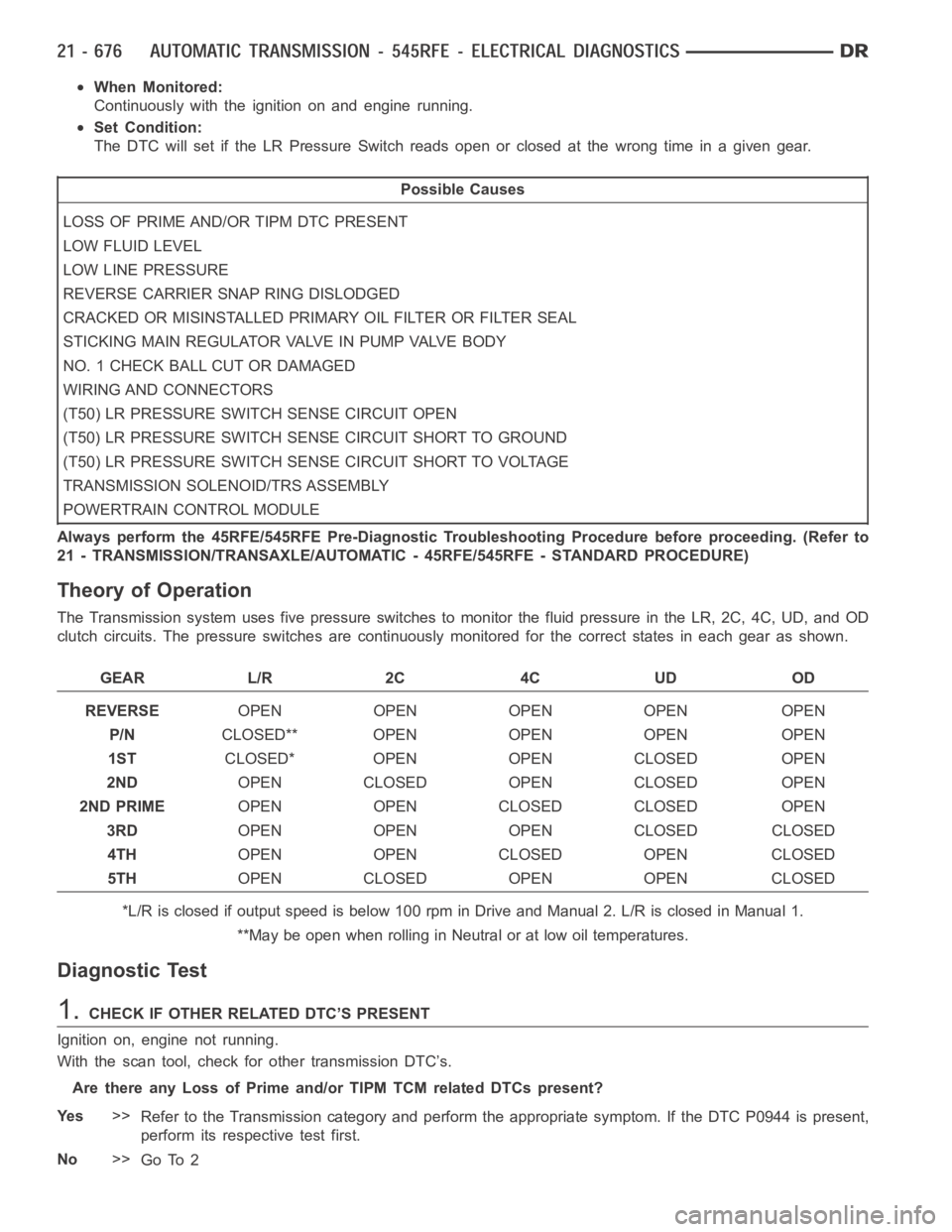
When Monitored:
Continuously with the ignition on and engine running.
Set Condition:
The DTC will set if the LR Pressure Switch reads open or closed at the wrong time in a given gear.
Possible Causes
LOSS OF PRIME AND/OR TIPM DTC PRESENT
LOW FLUID LEVEL
LOW LINE PRESSURE
REVERSE CARRIER SNAP RING DISLODGED
CRACKED OR MISINSTALLED PRIMARY OIL FILTER OR FILTER SEAL
STICKING MAIN REGULATOR VALVE IN PUMP VALVE BODY
NO. 1 CHECK BALL CUT OR DAMAGED
WIRING AND CONNECTORS
(T50) LR PRESSURE SWITCH SENSE CIRCUIT OPEN
(T50) LR PRESSURE SWITCH SENSE CIRCUIT SHORT TO GROUND
(T50) LR PRESSURE SWITCH SENSE CIRCUIT SHORT TO VOLTAGE
TRANSMISSION SOLENOID/TRS ASSEMBLY
POWERTRAIN CONTROL MODULE
Always perform the 45RFE/545RFE Pre-Diagnostic Troubleshooting Procedure before proceeding. (Refer to
21 - TRANSMISSION/TRANSAXLE/AUTOMATIC - 45RFE/545RFE - STANDARD PROCEDURE)
Theory of Operation
The Transmission system uses five pressure switches to monitor the fluid pressure in the LR, 2C, 4C, UD, and OD
clutch circuits. The pressure switches are continuously monitored for the correct states in each gear as shown.
GEAR L/R 2C 4C UD OD
REVERSEOPEN OPEN OPEN OPEN OPEN
P/NCLOSED** OPEN OPEN OPEN OPEN
1STCLOSED* OPEN OPEN CLOSED OPEN
2NDOPEN CLOSED OPEN CLOSED OPEN
2ND PRIMEOPEN OPEN CLOSED CLOSED OPEN
3RDOPEN OPEN OPEN CLOSED CLOSED
4THOPEN OPEN CLOSED OPEN CLOSED
5THOPEN CLOSED OPEN OPEN CLOSED
*L/R is closed if output speed is below 100 rpm in Drive and Manual 2. L/R is closed in Manual 1.
**May be open when rolling in Neutral or at low oil temperatures.
Diagnostic Test
1.CHECK IF OTHER RELATED DTC’S PRESENT
Ignition on, engine not running.
With the scan tool, check for other transmission DTC’s.
Are there any Loss of Prime and/or TIPM TCM related DTCs present?
Ye s>>
Refer to the Transmission category and perform the appropriate symptom. If the DTC P0944 is present,
perform its respective test first.
No>>
Go To 2
Page 3204 of 5267
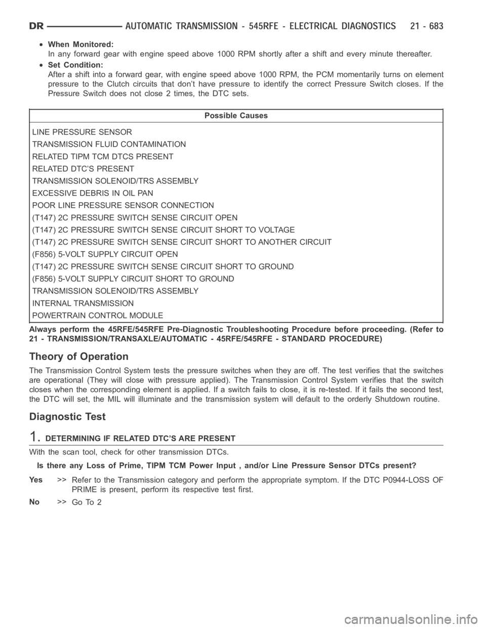
When Monitored:
In any forward gear with engine speed above 1000 RPM shortly after a shift and every minute thereafter.
Set Condition:
After a shift into a forward gear, with engine speed above 1000 RPM, the PCM momentarily turns on element
pressure to the Clutch circuits that don’t have pressure to identify the correct Pressure Switch closes. If the
Pressure Switch does not close 2 times, the DTC sets.
Possible Causes
LINE PRESSURE SENSOR
TRANSMISSION FLUID CONTAMINATION
RELATED TIPM TCM DTCS PRESENT
RELATED DTC’S PRESENT
TRANSMISSION SOLENOID/TRS ASSEMBLY
EXCESSIVE DEBRIS IN OIL PAN
POOR LINE PRESSURE SENSOR CONNECTION
(T147) 2C PRESSURE SWITCH SENSE CIRCUIT OPEN
(T147) 2C PRESSURE SWITCH SENSE CIRCUIT SHORT TO VOLTAGE
(T147) 2C PRESSURE SWITCH SENSE CIRCUIT SHORT TO ANOTHER CIRCUIT
(F856) 5-VOLT SUPPLY CIRCUIT OPEN
(T147) 2C PRESSURE SWITCH SENSE CIRCUIT SHORT TO GROUND
(F856) 5-VOLT SUPPLY CIRCUIT SHORT TO GROUND
TRANSMISSION SOLENOID/TRS ASSEMBLY
INTERNAL TRANSMISSION
POWERTRAIN CONTROL MODULE
Always perform the 45RFE/545RFE Pre-Diagnostic Troubleshooting Procedure before proceeding. (Refer to
21 - TRANSMISSION/TRANSAXLE/AUTOMATIC - 45RFE/545RFE - STANDARD PROCEDURE)
Theory of Operation
The Transmission Control System tests the pressure switches when they areoff. The test verifies that the switches
are operational (They will close with pressure applied). The Transmission Control System verifies that the switch
closes when the corresponding element is applied. If a switch fails to close, it is re-tested. If it fails the second test,
the DTC will set, the MIL will illuminate and the transmission system will default to the orderly Shutdown routine.
Diagnostic Test
1.DETERMINING IF RELATED DTC’S ARE PRESENT
With the scan tool, check for other transmission DTCs.
Is there any Loss of Prime, TIPM TCM Power Input , and/or Line Pressure Sensor DTCs present?
Ye s>>
Refer to the Transmission category and perform the appropriate symptom. If the DTC P0944-LOSS OF
PRIME is present, perform its respective test first.
No>>
Go To 2
Page 3231 of 5267
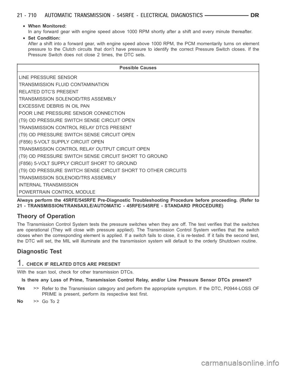
When Monitored:
In any forward gear with engine speed above 1000 RPM shortly after a shift and every minute thereafter.
Set Condition:
After a shift into a forward gear, with engine speed above 1000 RPM, the PCM momentarily turns on element
pressure to the Clutch circuits that don’t have pressure to identify the correct Pressure Switch closes. If the
Pressure Switch does not close 2 times, the DTC sets.
Possible Causes
LINE PRESSURE SENSOR
TRANSMISSION FLUID CONTAMINATION
RELATED DTC’S PRESENT
TRANSMISSION SOLENOID/TRS ASSEMBLY
EXCESSIVE DEBRIS IN OIL PAN
POOR LINE PRESSURE SENSOR CONNECTION
(T9) OD PRESSURE SWITCH SENSE CIRCUIT OPEN
TRANSMISSION CONTROL RELAY DTCS PRESENT
(T9) OD PRESSURE SWITCH SENSE CIRCUIT OPEN
(F856) 5-VOLT SUPPLY CIRCUIT OPEN
TRANSMISSION CONTROL RELAY OUTPUT CIRCUIT OPEN
(T9) OD PRESSURE SWITCH SENSE CIRCUIT SHORT TO GROUND
(F856) 5-VOLT SUPPLY CIRCUIT SHORT TO GROUND
(T9) OD PRESSURE SWITCH SENSE CIRCUIT SHORT TO OTHER CIRCUITS
TRANSMISSION SOLENOID/TRS ASSEMBLY
INTERNAL TRANSMISSION
POWERTRAIN CONTROL MODULE
Always perform the 45RFE/545RFE Pre-Diagnostic Troubleshooting Procedure before proceeding. (Refer to
21 - TRANSMISSION/TRANSAXLE/AUTOMATIC - 45RFE/545RFE - STANDARD PROCEDURE)
Theory of Operation
The Transmission Control System tests the pressure switches when they areoff. The test verifies that the switches
are operational (They will close with pressure applied). The Transmission Control System verifies that the switch
closes when the corresponding element is applied. If a switch fails to close, it is re-tested. If it fails the second test,
the DTC will set, the MIL will illuminate and the transmission system will default to the orderly Shutdown routine.
Diagnostic Test
1.CHECK IF RELATED DTCS ARE PRESENT
With the scan tool, check for other transmission DTCs.
Is there any Loss of Prime, Transmission Control Relay, and/or Line Pressure Sensor DTCs present?
Ye s>>
Refer to the Transmission category and perform the appropriate symptom. If the DTC, P0944-LOSS OF
PRIME is present, perform its respective test first.
No>>
Go To 2
Page 3248 of 5267
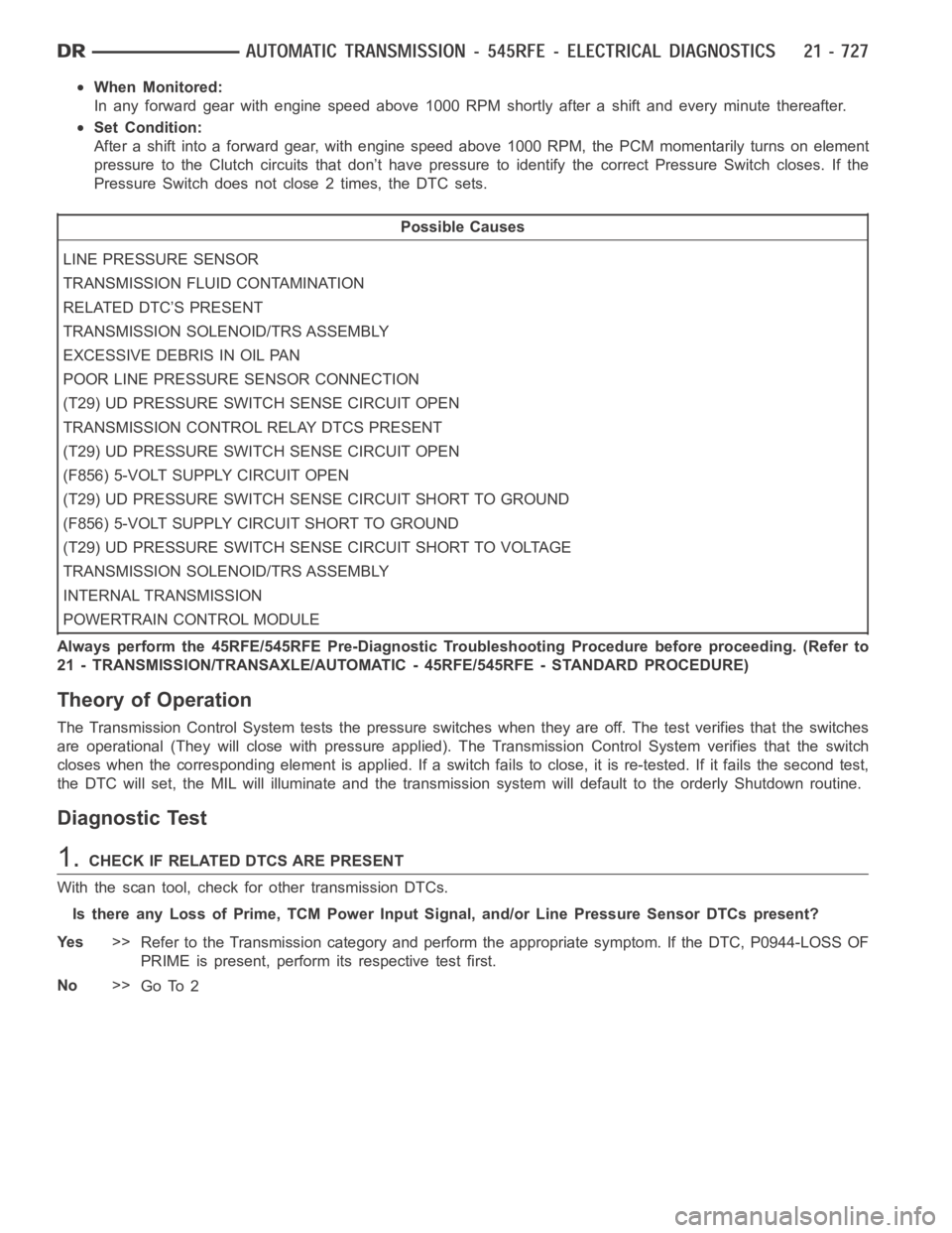
When Monitored:
In any forward gear with engine speed above 1000 RPM shortly after a shift and every minute thereafter.
Set Condition:
After a shift into a forward gear, with engine speed above 1000 RPM, the PCM momentarily turns on element
pressure to the Clutch circuits that don’t have pressure to identify the correct Pressure Switch closes. If the
Pressure Switch does not close 2 times, the DTC sets.
Possible Causes
LINE PRESSURE SENSOR
TRANSMISSION FLUID CONTAMINATION
RELATED DTC’S PRESENT
TRANSMISSION SOLENOID/TRS ASSEMBLY
EXCESSIVE DEBRIS IN OIL PAN
POOR LINE PRESSURE SENSOR CONNECTION
(T29) UD PRESSURE SWITCH SENSE CIRCUIT OPEN
TRANSMISSION CONTROL RELAY DTCS PRESENT
(T29) UD PRESSURE SWITCH SENSE CIRCUIT OPEN
(F856) 5-VOLT SUPPLY CIRCUIT OPEN
(T29) UD PRESSURE SWITCH SENSE CIRCUIT SHORT TO GROUND
(F856) 5-VOLT SUPPLY CIRCUIT SHORT TO GROUND
(T29) UD PRESSURE SWITCH SENSE CIRCUIT SHORT TO VOLTAGE
TRANSMISSION SOLENOID/TRS ASSEMBLY
INTERNAL TRANSMISSION
POWERTRAIN CONTROL MODULE
Always perform the 45RFE/545RFE Pre-Diagnostic Troubleshooting Procedure before proceeding. (Refer to
21 - TRANSMISSION/TRANSAXLE/AUTOMATIC - 45RFE/545RFE - STANDARD PROCEDURE)
Theory of Operation
The Transmission Control System tests the pressure switches when they areoff. The test verifies that the switches
are operational (They will close with pressure applied). The Transmission Control System verifies that the switch
closes when the corresponding element is applied. If a switch fails to close, it is re-tested. If it fails the second test,
the DTC will set, the MIL will illuminate and the transmission system will default to the orderly Shutdown routine.
Diagnostic Test
1.CHECK IF RELATED DTCS ARE PRESENT
With the scan tool, check for other transmission DTCs.
Is there any Loss of Prime, TCM Power Input Signal, and/or Line Pressure Sensor DTCs present?
Ye s>>
Refer to the Transmission category and perform the appropriate symptom. If the DTC, P0944-LOSS OF
PRIME is present, perform its respective test first.
No>>
Go To 2