2006 DODGE RAM SRT-10 ESP
[x] Cancel search: ESPPage 3256 of 5267
When Monitored:
Continuously with the ignition on and engine running.
Set Condition:
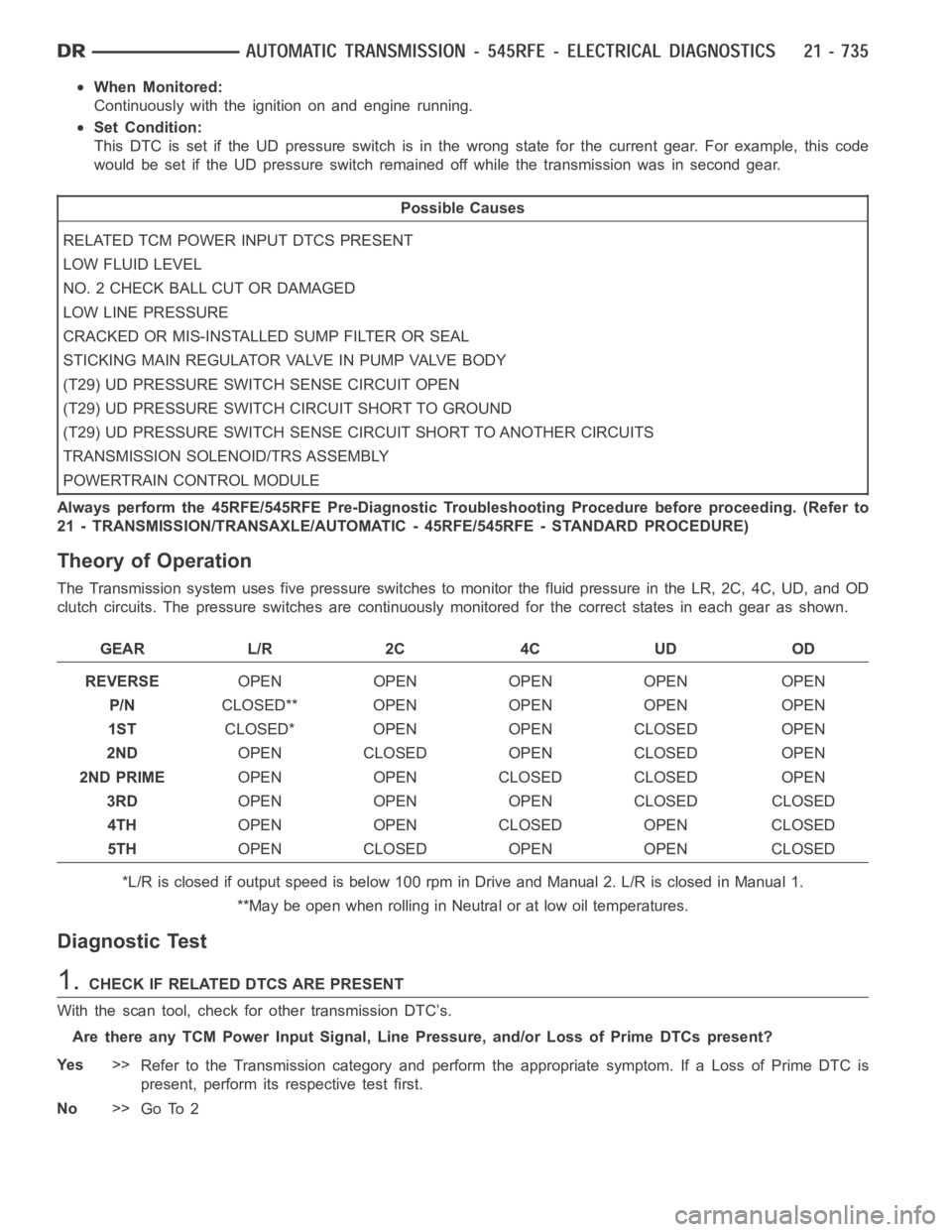
This DTC is set if the UD pressure switch is in the wrong state for the currentgear. For example, this code
would be set if the UD pressure switch remained off while the transmission was in second gear.
Possible Causes
RELATED TCM POWER INPUT DTCS PRESENT
LOW FLUID LEVEL
NO. 2 CHECK BALL CUT OR DAMAGED
LOW LINE PRESSURE
CRACKED OR MIS-INSTALLED SUMP FILTER OR SEAL
STICKING MAIN REGULATOR VALVE IN PUMP VALVE BODY
(T29) UD PRESSURE SWITCH SENSE CIRCUIT OPEN
(T29) UD PRESSURE SWITCH CIRCUIT SHORT TO GROUND
(T29) UD PRESSURE SWITCH SENSE CIRCUIT SHORT TO ANOTHER CIRCUITS
TRANSMISSION SOLENOID/TRS ASSEMBLY
POWERTRAIN CONTROL MODULE
Always perform the 45RFE/545RFE Pre-Diagnostic Troubleshooting Procedure before proceeding. (Refer to
21 - TRANSMISSION/TRANSAXLE/AUTOMATIC - 45RFE/545RFE - STANDARD PROCEDURE)
Theory of Operation
The Transmission system uses five pressure switches to monitor the fluid pressure in the LR, 2C, 4C, UD, and OD
clutch circuits. The pressure switches are continuously monitored for the correct states in each gear as shown.
GEAR L/R 2C 4C UD OD
REVERSEOPEN OPEN OPEN OPEN OPEN
P/NCLOSED** OPEN OPEN OPEN OPEN
1STCLOSED* OPEN OPEN CLOSED OPEN
2NDOPEN CLOSED OPEN CLOSED OPEN
2ND PRIMEOPEN OPEN CLOSED CLOSED OPEN
3RDOPEN OPEN OPEN CLOSED CLOSED
4THOPEN OPEN CLOSED OPEN CLOSED
5THOPEN CLOSED OPEN OPEN CLOSED
*L/R is closed if output speed is below 100 rpm in Drive and Manual 2. L/R is closed in Manual 1.
**May be open when rolling in Neutral or at low oil temperatures.
Diagnostic Test
1.CHECK IF RELATED DTCS ARE PRESENT
With the scan tool, check for other transmission DTC’s.
Are there any TCM Power Input Signal, Line Pressure, and/or Loss of Prime DTCs present?
Ye s>>
Refer to the Transmission category and perform the appropriate symptom. If a Loss of Prime DTC is
present, perform its respective test first.
No>>
Go To 2
Page 3271 of 5267
When Monitored:
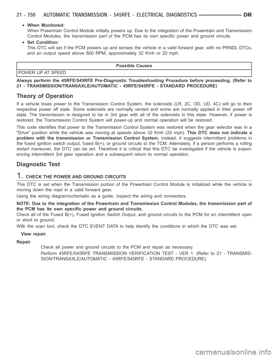
When Powertrain Control Module initially powers up. Due to the integration of the Powertrain and Transmission
Control Modules, the transmission part of the PCM has its own specific power and ground circuits.
Set Condition:
This DTC will set if the PCM powers up and senses the vehicle in a valid forwardgear,withnoPRNDLDTCs,
and an output speed above 800 RPM, approximately 32 Kmh or 20 mph.
Possible Causes
POWER UP AT SPEED
Always perform the 45RFE/545RFE Pre-Diagnostic Troubleshooting Procedure before proceeding. (Refer to
21 - TRANSMISSION/TRANSAXLE/AUTOMATIC - 45RFE/545RFE - STANDARD PROCEDURE)
Theory of Operation
If a vehicle loses power to the Transmission Control System, the solenoids(LR, 2C, OD, UD, 4C) will go to their
respective power off state. Some solenoids are normally vented and some are normally applied in their power off
state. The transmission is designed to be in 3rd gear with all of the solenoids in this state. However, if power is
restored, the Transmission Control System will power-up and normal operation will be restored.
This code identifies that power to the Transmission Control System was restored when the gear selector was in a
Driveposition while the vehicle was moving at speeds above 32 Kmh (20 mph).This DTC does not indicate a
problem with the transmission or Transmission Control System,instead, it suggests intermittent problems in
the fused ignition switch output, fused B(+), or ground circuits to the TCM. Alternately, if a person performs a rolling
restart maneuver, the DTC can be set. Therefore it is critical that this DTCbe investigated if the vehicle is experi-
encing intermittent 3rd gear operation and a subsequent return to normal operation.
Diagnostic Test
1.CHECK THE POWER AND GROUND CIRCUITS
This DTC is set when the Transmission portion of the Powertrain Control Module is initialized while the vehicle is
movingdowntheroadinavalidforwardgear.
Using the wiring diagram/schematic as a guide, inspect the wiring and connectors.
NOTE: Due to the integration of the Powertrain and Transmission Control Modules, the transmission part of
the PCM has its own specific power and ground circuits.
Check all of the Fused B(+), Fused Ignition Switch Output, and ground circuits to the PCM for an intermittent open
or short to ground.
With the scan tool, check the DTC EVENT DATA to help identify the conditionsin which the DTC was set.
View repair.
Repair
Check all power and ground circuits to the PCM and repair as necessary.
Perform 45RFE/545RFE TRANSMISSION VERIFICATION TEST - VER 1. (Refer to 21- TRANSMIS-
SION/TRANSAXLE/AUTOMATIC - 45RFE/545RFE - STANDARD PROCEDURE)
Page 3289 of 5267
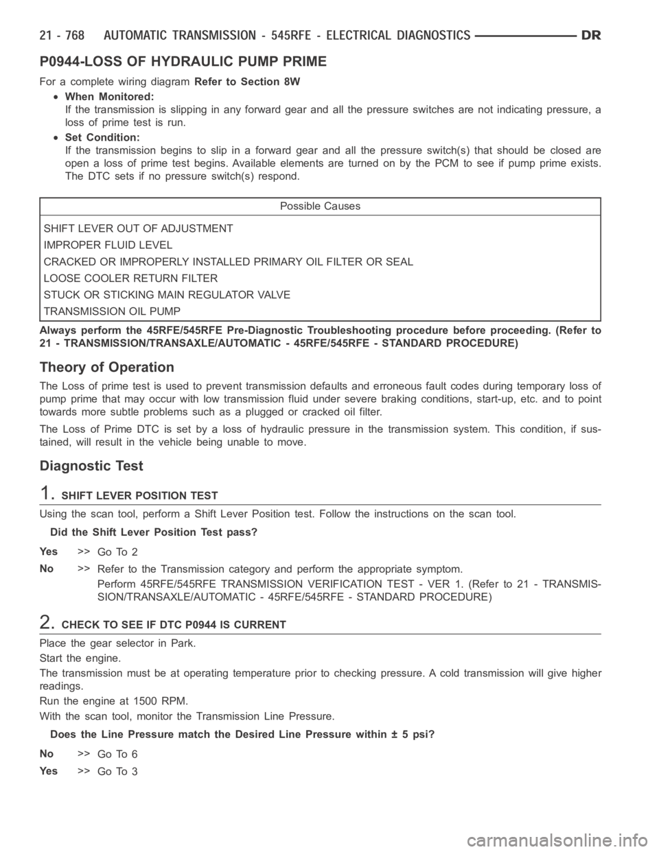
P0944-LOSS OF HYDRAULIC PUMP PRIME
For a complete wiring diagramRefer to Section 8W
When Monitored:
If the transmission is slipping in any forward gear and all the pressure switches are not indicating pressure, a
loss of prime test is run.
Set Condition:
If the transmission begins to slip in a forward gear and all the pressure switch(s) that should be closed are
open a loss of prime test begins. Available elements are turned on by the PCMto see if pump prime exists.
The DTC sets if no pressure switch(s) respond.
Possible Causes
SHIFT LEVER OUT OF ADJUSTMENT
IMPROPER FLUID LEVEL
CRACKED OR IMPROPERLY INSTALLED PRIMARY OIL FILTER OR SEAL
LOOSE COOLER RETURN FILTER
STUCK OR STICKING MAIN REGULATOR VALVE
TRANSMISSION OIL PUMP
Always perform the 45RFE/545RFE Pre-Diagnostic Troubleshooting procedure before proceeding. (Refer to
21 - TRANSMISSION/TRANSAXLE/AUTOMATIC - 45RFE/545RFE - STANDARD PROCEDURE)
Theory of Operation
The Loss of prime test is used to prevent transmission defaults and erroneous fault codes during temporary loss of
pump prime that may occur with low transmission fluid under severe brakingconditions, start-up, etc. and to point
towards more subtle problems such as a plugged or cracked oil filter.
The Loss of Prime DTC is set by a loss of hydraulic pressure in the transmission system. This condition, if sus-
tained, will result in the vehicle being unable to move.
Diagnostic Test
1.SHIFT LEVER POSITION TEST
Using the scan tool, perform a Shift Lever Position test. Follow the instructions on the scan tool.
Did the Shift Lever Position Test pass?
Ye s>>
Go To 2
No>>
Refer to the Transmission category and perform the appropriate symptom.
Perform 45RFE/545RFE TRANSMISSION VERIFICATION TEST - VER 1. (Refer to 21- TRANSMIS-
SION/TRANSAXLE/AUTOMATIC - 45RFE/545RFE - STANDARD PROCEDURE)
2.CHECK TO SEE IF DTC P0944 IS CURRENT
Place the gear selector in Park.
Start the engine.
The transmission must be at operating temperature prior to checking pressure. A cold transmission will give higher
readings.
Run the engine at 1500 RPM.
With the scan tool, monitor the Transmission Line Pressure.
Does the Line Pressure match the Desired Line Pressure within ± 5 psi?
No>>
Go To 6
Ye s>>
Go To 3
Page 3292 of 5267
When Monitored:
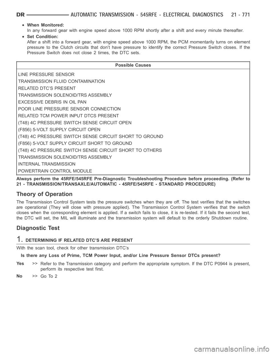
In any forward gear with engine speed above 1000 RPM shortly after a shift and every minute thereafter.
Set Condition:
After a shift into a forward gear, with engine speed above 1000 RPM, the PCM momentarily turns on element
pressure to the Clutch circuits that don’t have pressure to identify the correct Pressure Switch closes. If the
Pressure Switch does not close 2 times, the DTC sets.
Possible Causes
LINE PRESSURE SENSOR
TRANSMISSION FLUID CONTAMINATION
RELATED DTC’S PRESENT
TRANSMISSION SOLENOID/TRS ASSEMBLY
EXCESSIVE DEBRIS IN OIL PAN
POOR LINE PRESSURE SENSOR CONNECTION
RELATED TCM POWER INPUT DTCS PRESENT
(T48) 4C PRESSURE SWITCH SENSE CIRCUIT OPEN
(F856) 5-VOLT SUPPLY CIRCUIT OPEN
(T48) 4C PRESSURE SWITCH SENSE CIRCUIT SHORT TO GROUND
(F856) 5-VOLT SUPPLY CIRCUIT SHORT TO GROUND
(T48) 4C PRESSURE SWITCH SENSE CIRCUIT SHORT TO OTHERS
TRANSMISSION SOLENOID/TRS ASSEMBLY
INTERNAL TRANSMISSION
POWERTRAIN CONTROL MODULE
Always perform the 45RFE/545RFE Pre-Diagnostic Troubleshooting Procedure before proceeding. (Refer to
21 - TRANSMISSION/TRANSAXLE/AUTOMATIC - 45RFE/545RFE - STANDARD PROCEDURE)
Theory of Operation
The Transmission Control System tests the pressure switches when they areoff. The test verifies that the switches
are operational (They will close with pressure applied). The Transmission Control System verifies that the switch
closes when the corresponding element is applied. If a switch fails to close, it is re-tested. If it fails the second test,
the DTC will set, the MIL will illuminate and the transmission system will default to the orderly Shutdown routine.
Diagnostic Test
1.DETERMINING IF RELATED DTC’S ARE PRESENT
With the scan tool, check for other transmission DTC’s
Is there any Loss of Prime, TCM Power Input, and/or Line Pressure Sensor DTCspresent?
Ye s>>
Refer to the Transmission category and perform the appropriate symptom. If the DTC P0944 is present,
perform its respective test first.
No>>
Go To 2
Page 3321 of 5267

P1736-GEAR RATIO ERROR IN 2ND PRIME
For a complete wiring diagramRefer to Section 8W.
When Monitored:
Continuously with the ignition on, engine running, with the transmissionin gear.
Set Condition:
If the ratio of the Input RPM to the Output RPM does not match the current gearratio. This DTC can take up
to five minutes of problem identification before illuminating the MIL
Possible Causes
RELATED DTC’S PRESENT
INPUT SPEED SENSOR OR WIRING
LOW FLUID LEVEL
CRACKED OR MIS-INSTALLED PRIMARY OIL FILTER OR SEAL
WORN SOLENOID SWITCH VALVE OR PLUGS
STUCK OR STICKING MAIN REGULATOR VALVE
BURNED UD OR 4C CLUTCH
CUT 4C OR UD PISTON SEAL
BROKEN 4C PISTON CASTING
BROKEN OR MISSING 4C BLEED ORIFICE
BROKEN OR MISSING UD BLEED ORIFICE
CUT 4C OR UD ACCUMULATOR PISTON SEAL
CRACKED 4C OR UD ACCUMULATOR PISTON
EXTRA CHECK BALL IN PASSAGE DOWNSTREAM OF #7 CHECK BALL POCKET
TRANSMISSION SOLENOID/TRS ASSEMBLY
BROKEN WELD - REACTION CARRIER TO REVERSE SUN GEAR
MISSING TEETH ON INPUT CLUTCH HUB TONE WHEEL
Always perform the 45RFE/545RFE Pre-Diagnostic Troubleshooting Procedure before proceeding. (Refer to
21 - TRANSMISSION/TRANSAXLE/AUTOMATIC - 45RFE/545RFE - STANDARD PROCEDURE)
Theory of Operation
The transmission system uses two speed sensors, one to measure input RPM and one to measure output RPM.
These inputs are essential for proper transmission operation. Therefore, the integrity of this data is verified through
the following checks:
1) When in gear, if the gear ratio does not compare to a known gear ratio, the corresponding in-gear trouble code
is set (DTCs P0731-36).
2) An excessive change in input or output speeds indicating signal intermittent which may result in the DTCs P0715
and/or P0720 to set.
3) If the common speed sensor ground circuit is lost, both sensor inputs will read the signal from the input speed
sensor at idle in neutral. Since the input speed sensor reads 60 teeth from the input clutch hub and the output
speed sensor reads 30 teeth from the park gear, the result is an apparent speed ratio of 1:2 and may cause the
DTC P1794 to set when at a stop.
Page 3336 of 5267
When Monitored:
The gear ratio is monitored continuously while the Transmission is in gear.
Set Condition:
After a controller reset in neutral and a ratio of input to output, of 1 to 2. ThisDTCcantakeuptofiveminutes
of problem identification before illuminating the MIL.
Possible Causes
(T13) SPEED SENSOR GROUND CIRCUIT OPEN
(T13) SPEED SENSOR GROUND CIRCUIT SHORT TO GROUND
(T13) SPEED SENSOR GROUND CIRCUIT SHORT TO VOLTAGE
POWERTRAIN CONTROL MODULE
Always perform the 45RFE/545RFE Pre-Diagnostic Troubleshooting Procedure before proceeding. (Refer to
21 - TRANSMISSION/TRANSAXLE/AUTOMATIC - 45RFE/545RFE - STANDARD PROCEDURE)
Theory of Operation
The transmission system uses two speed sensors, one to measure input RPM and one to measure output RPM.
These inputs are essential for proper transmission operation. Therefore, the integrity of this data is verified through
the following checks:
1) When in gear, if the gear ratio does not compare to a known gear ratio, the corresponding in-gear trouble code
is set (DTCs P0731–36).
2) An excessive change in input or output speeds indicating signal intermittent which may result in the DTCs P0715
and/or P0720 to set.
3) If the common speed sensor ground circuit is lost, both sensor inputs will read the signal from the input speed
sensor at idle in neutral. Since the input speed sensor reads 60 teeth from the input clutch hub and the output
speed sensor reads 30 teeth from the park gear, the result is an apparent speed ratio of 1:2 and may cause the
DTC P1794 to set when at a stop.
Diagnostic Test
1.CHECK TO SEE IF DTC P1794 IS CURRENT
Engine Running, Shift lever in park.
With the scan tool, read the Transmission Output and Input Speed Sensor states.
Is the Output Speed Sensor reading twice the Input Speed Sensor reading?
Ye s>>
Go To 2
No>>
Go To 6
2.PCM AND WIRING
Turn the ignition off to the lock position.
Remove the Ignition Switch Feed fuse from the TIPM.
CAUTION: Removal of the Ignition Switch Feed fuse from the TIPM will prevent the vehicle from being
startedingear.
WARNING: The Ignition Switch Feed fuse must be removed from the TIPM. Failure to do so can result in
personal injury or death.
Install the Transmission Simulator, Miller tool 8333.
With the Transmission Simulator, set the Input/Output Speed selector switch to the
3000/1000position. Turn the
Input/Output Speed switch to
ON.
Ignition on, engine not running.
Page 3350 of 5267
When Monitored:
Initially at power-up, then every 10 seconds thereafter. The solenoid circuits will also be tested immediately
after a gear ratio or pressure switch error is detected.
Set Condition:
After three consecutive solenoid continuity test failures, or one failure if test is run in response to a gear ratio
or pressure switch error.Note: This DTC is strictly an electrical fault and does not apply to any internal
transmission failures.
Possible Causes
RELATED TCM POWER INPUT DTCS PRESENT
(T118) MS SOLENOID CONTROL CIRCUIT SHORT TO OTHER CIRCUITS
(T118) MS SOLENOID CONTROL CIRCUIT OPEN
(T118) MS SOLENOID CONTROL CIRCUIT SHORT TO GROUND
TRANSMISSION SOLENOID/TRS ASSEMBLY
POWERTRAIN CONTROL MODULE
Always perform the 45RFE/545RFE Pre-Diagnostic Troubleshooting Procedure before proceeding. (Refer to
21 - TRANSMISSION/TRANSAXLE/AUTOMATIC - 45RFE/545RFE - STANDARD PROCEDURE)
Theory of Operation
The Transmission Control System uses six electronically controlled solenoids that allow hydraulic fluid to be applied
to various friction elements (clutches), which enables the gear requested. The continuity of each solenoid circuit is
periodically tested. Each inactive solenoid is turned on for a few milliseconds, then off. Each active solenoid is
turned off for a few milliseconds, then on. This pulsing of voltage to the solenoid causes an inductive spike which
can be sensed by the Transmission Control System. If an inductive spike is not sensed by the Transmission Control
System during the continuity check, it is tested again. If the test fails three consecutive times, the appropriate Diag-
nostic Trouble Code (DTC) is set. If the solenoid test is run in response to agear ratio or pressure switch error, one
failure will result in setting the appropriate DTC.Note: This DTC is strictly an electrical fault and does not apply
to any internal transmission failures.
Diagnostic Test
1.RELATED TCM POWER INPUT DTCS PRESENT
With the scan tool, check for other transmission DTCs.
Are there any TCM Power Input DTCs present?
Ye s>>
Refer to the Transmission category and perform the appropriate symptom.
No>>
Go To 2
2.TRANSMISSION SOLENOID/TRS ASSEMBLY
Turn the ignition off to the lock position.
Remove the Ignition Switch Feed fuse from the TIPM.
CAUTION: Removal of the Ignition Switch Feed fuse from the TIPM will prevent the vehicle from being
startedingear.
WARNING: The Ignition Switch Feed fuse must be removed from the TIPM. Failure to do so can result in
personal injury or death.
Install Transmission Simulator, Miller tool #8333.
Ignition on, engine not running.
With the scan tool, actuate the MS Solenoid.
Page 3365 of 5267
AUTOMATIC TRANSMISSION - 45RFE/545RFE-SERVICEINFORMATION
DESCRIPTION
The 45RFE/545RFE automatic transmissions is a sophisticated, multi-range, electronically controlled transmission
which combines optimized gear ratios for responsive performance, state of the art efficiency features and low NVH.
Other features include driver adaptive shifting and three planetary gearsets to provide wide ratio capability with
precise ratio steps for optimum driveability. The three planetary gear sets also make available a unique alternate
second gear ratio. The primary 2nd gear ratio fits between 1st and 3rd gearsfor normal through-gear accelerations.
The alternate second gear ratio (2prime) allows smoother 4-2 kickdowns athigh speeds to provide 2nd gear pass-
ing performance over a wider highway cruising range.
The hydraulic portion of the transmission consists of the transmission fluid, fluid passages, hydraulic valves, and
various line pressure control components.
The primary mechanical components of the transmission consist of the following:
Three multiple disc input clutches
Three multiple disc holding clutches
Five hydraulic accumulators
Three planetary gear sets
Dual Stage Hydraulic oil pump
Valve body
Solenoid pack
The Transmission Control Module (TCM) is the “heart” or “brain” of the electronic control system and relies on infor-
mation from various direct and indirect inputs (sensors, switches, etc.)to determine driver demand and vehicle oper-
ating conditions. Depending on the vehicle configuration, the TCM may be astandalone module or it it may be
housed along with the Powertrain Control Module (PCM) in a single module. With this information, the TCM can
calculate and perform timely and quality shifts through various output orcontrol devices (solenoid pack, transmission
control relay, etc.).
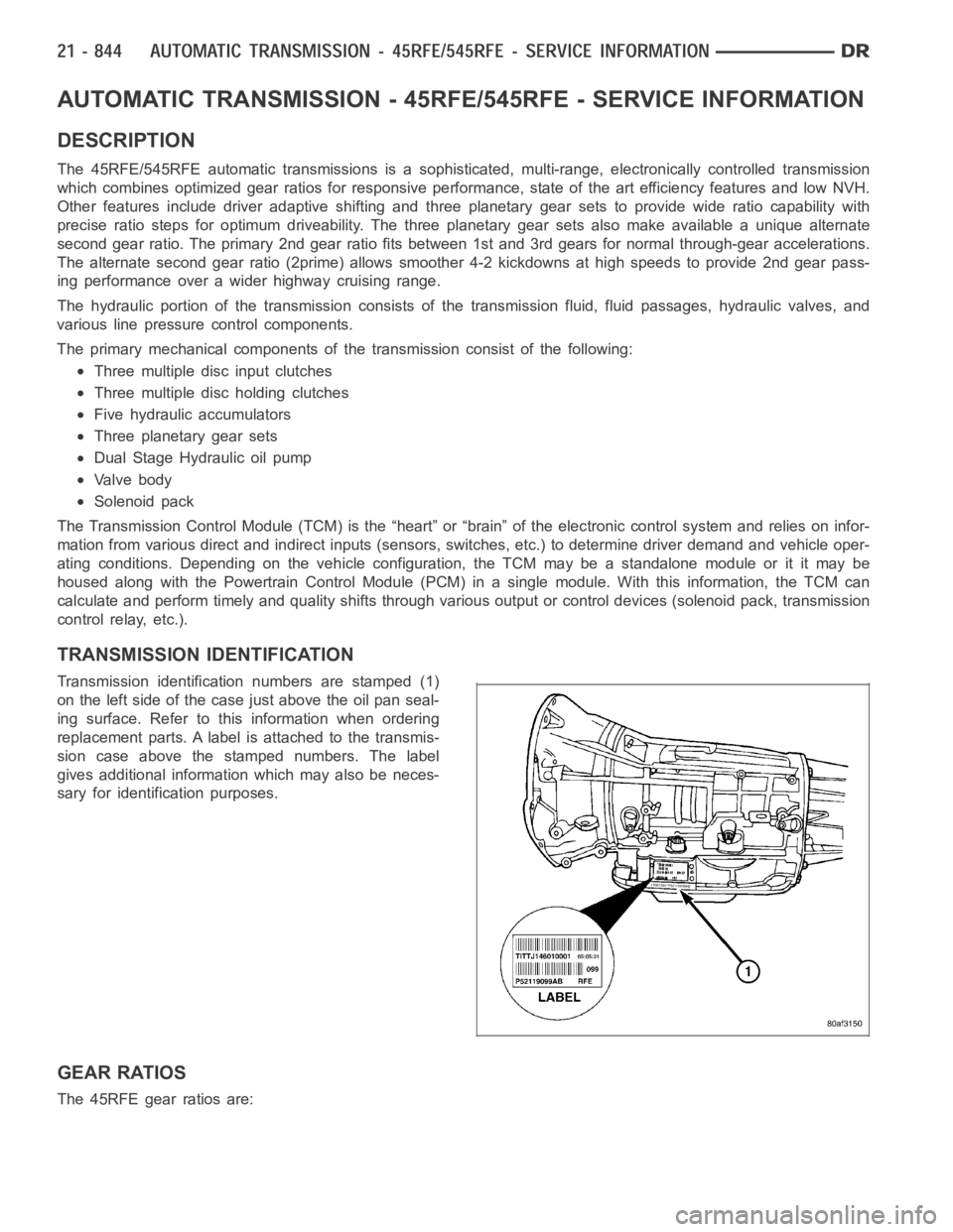
TRANSMISSION IDENTIFICATION
Transmission identification numbers are stamped (1)
on the left side of the case just above the oil pan seal-
ing surface. Refer to this information when ordering
replacement parts. A label is attached to the transmis-
sion case above the stamped numbers. The label
gives additional information which may also be neces-
sary for identification purposes.
GEAR RATIOS
The 45RFE gear ratios are: