Page 4262 of 5267
MOTOR-SHIFT
DESCRIPTION
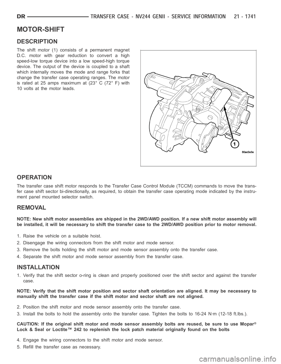
The shift motor (1) consists of a permanent magnet
D.C. motor with gear reduction to convert a high
speed-low torque device into a low speed-high torque
device. The output of the device is coupled to a shaft
which internally moves the mode and range forks that
change the transfer case operating ranges. The motor
is rated at 25 amps maximum at (23° C (72° F) with
10 volts at the motor leads.
OPERATION
The transfer case shift motor responds to the Transfer Case Control Module(TCCM) commands to move the trans-
fer case shift sector bi-directionally, as required, to obtain the transfer case operating mode indicated by the instru-
ment panel mounted selector switch.
REMOVAL
NOTE: New shift motor assemblies are shipped in the 2WD/AWD position. If a new shift motor assembly will
be installed, it will be necessary to shift the transfer case to the 2WD/AWDposition prior to motor removal.
1. Raise the vehicle on a suitable hoist.
2. Disengage the wiring connectors from the shift motor and mode sensor.
3. Remove the bolts holding the shift motor and mode sensor assembly onto the transfer case.
4. Separate the shift motor and mode sensor assembly from the transfer case.
INSTALLATION
1. Verify that the shift sector o-ring is clean and properly positioned over the shift sector and against the transfer
case.
NOTE: Verify that the shift motor position and sector shaft orientation are aligned. It may be necessary to
manually shift the transfer case if the shift motor and sector shaft are notaligned.
2. Position the shift motor and mode sensor assembly onto the transfer case.
3. Install the bolts to hold the assembly onto the transfer case. Tighten the bolts to 16-24 Nꞏm (12-18 ft.lbs.).
CAUTION: If the original shift motor and mode sensor assembly bolts are reused, be sure to use Mopar
Lock & Seal or Loctite™ 242 to replenish the lock patch material originallyfound on the bolts
4. Engage the wiring connectors to the shift motor and mode sensor.
5. Refill the transfer case as necessary.
Page 4283 of 5267
SHIFT FORKS/HUBS/SLEEVES
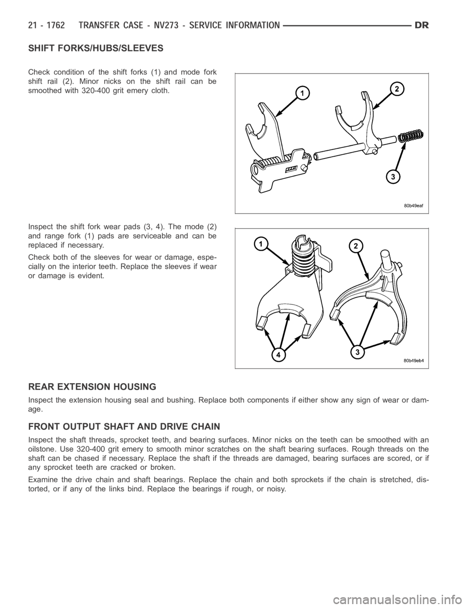
Check condition of the shift forks (1) and mode fork
shift rail (2). Minor nicks on the shift rail can be
smoothed with 320-400 grit emery cloth.
Inspect the shift fork wear pads (3, 4). The mode (2)
and range fork (1) pads are serviceable and can be
replaced if necessary.
Check both of the sleeves for wear or damage, espe-
cially on the interior teeth. Replace the sleeves if wear
or damage is evident.
REAR EXTENSION HOUSING
Inspect the extension housing seal and bushing. Replace both components if either show any sign of wear or dam-
age.
FRONT OUTPUT SHAFT AND DRIVE CHAIN
Inspect the shaft threads, sprocket teeth, and bearing surfaces. Minor nicksontheteethcanbesmoothedwithan
oilstone. Use 320-400 grit emery to smooth minor scratches on the shaft bearing surfaces. Rough threads on the
shaft can be chased if necessary. Replace the shaft if the threads are damaged, bearing surfaces are scored, or if
any sprocket teeth are cracked or broken.
Examine the drive chain and shaft bearings. Replace the chain and both sprockets if the chain is stretched, dis-
torted, or if any of the links bind. Replace the bearings if rough, or noisy.
Page 4312 of 5267
MOTOR-SHIFT
DESCRIPTION
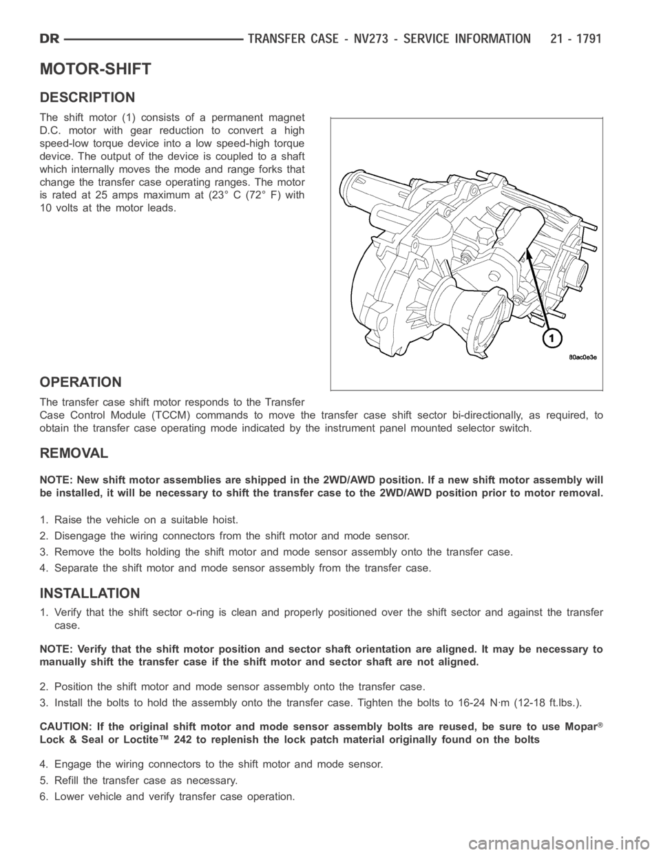
The shift motor (1) consists of a permanent magnet
D.C. motor with gear reduction to convert a high
speed-low torque device into a low speed-high torque
device. The output of the device is coupled to a shaft
which internally moves the mode and range forks that
change the transfer case operating ranges. The motor
is rated at 25 amps maximum at (23° C (72° F) with
10 volts at the motor leads.
OPERATION
The transfer case shift motor responds to the Transfer
Case Control Module (TCCM) commands to move the transfer case shift sectorbi-directionally, as required, to
obtain the transfer case operating mode indicated by the instrument panelmounted selector switch.
REMOVAL
NOTE: New shift motor assemblies are shipped in the 2WD/AWD position. If a new shift motor assembly will
be installed, it will be necessary to shift the transfer case to the 2WD/AWDposition prior to motor removal.
1. Raise the vehicle on a suitable hoist.
2. Disengage the wiring connectors from the shift motor and mode sensor.
3. Remove the bolts holding the shift motor and mode sensor assembly onto the transfer case.
4. Separate the shift motor and mode sensor assembly from the transfer case.
INSTALLATION
1. Verify that the shift sector o-ring is clean and properly positioned over the shift sector and against the transfer
case.
NOTE: Verify that the shift motor position and sector shaft orientation are aligned. It may be necessary to
manually shift the transfer case if the shift motor and sector shaft are notaligned.
2. Position the shift motor and mode sensor assembly onto the transfer case.
3. Install the bolts to hold the assembly onto the transfer case. Tighten the bolts to 16-24 Nꞏm (12-18 ft.lbs.).
CAUTION: If the original shift motor and mode sensor assembly bolts are reused, be sure to use Mopar
Lock & Seal or Loctite™ 242 to replenish the lock patch material originallyfound on the bolts
4. Engage the wiring connectors to the shift motor and mode sensor.
5. Refill the transfer case as necessary.
6. Lower vehicle and verify transfer case operation.
Page 4441 of 5267
SIDE VIEW MIRROR GLASS
REMOVAL
STANDARD MIRROR
WARNING: Always wear eye and hand protection
when servicing the mirror assembly. Failure to
observe this warning may result in personal injury
from broken glass.
1. Position the glass (3) in the mirror (2) as shown to
access the two outboard mirror housing retainer
clips (1).
2. Disengage the three mirror housing retainer clips
(2) (start with the two outboard clips) and remove
the cover.
3. Disengage the lower glass retainer clip (2) from the
mirror motor.
4. Slide the mirror glass (1) upward from the mirror
motor and remove the glass from the motor.
NOTE: When disconnecting the wire harness con-
nectors from the heated mirror glass terminals,
note the location of each connector and its
respective terminal for installation reference.
5. If equipped with heated mirrors, disconnect the
wire harness connectors from the mirror glass.
Page 4442 of 5267
TOW PACKAGE MIRROR
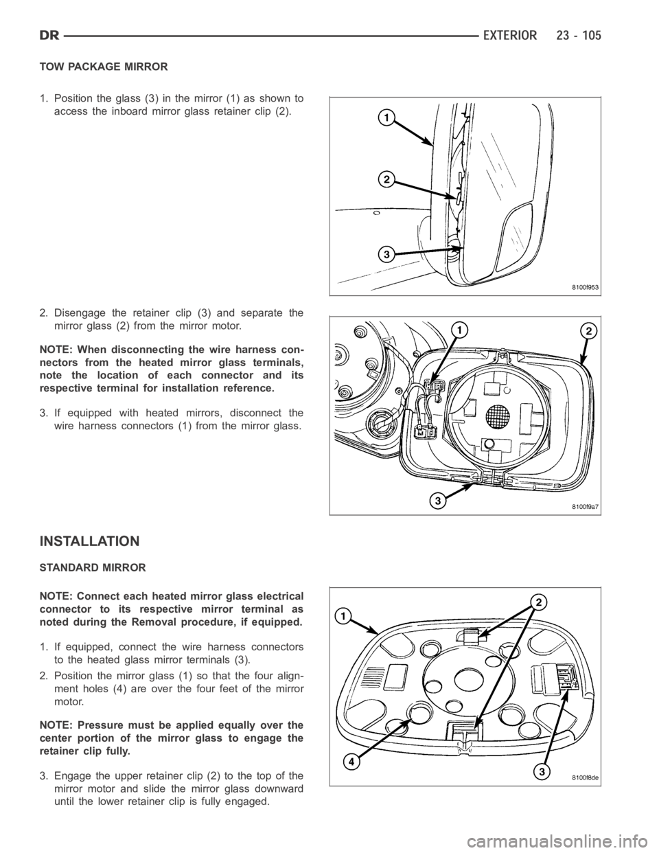
1. Position the glass (3) in the mirror (1) as shown to
access the inboard mirror glass retainer clip (2).
2. Disengage the retainer clip (3) and separate the
mirror glass (2) from the mirror motor.
NOTE: When disconnecting the wire harness con-
nectors from the heated mirror glass terminals,
note the location of each connector and its
respective terminal for installation reference.
3. If equipped with heated mirrors, disconnect the
wire harness connectors (1) from the mirror glass.
INSTALLATION
STANDARD MIRROR
NOTE: Connect each heated mirror glass electrical
connector to its respective mirror terminal as
noted during the Removal procedure, if equipped.
1. If equipped, connect the wire harness connectors
to the heated glass mirror terminals (3).
2. Position the mirror glass (1) so that the four align-
ment holes (4) are over the four feet of the mirror
motor.
NOTE: Pressure must be applied equally over the
center portion of the mirror glass to engage the
retainer clip fully.
3. Engage the upper retainer clip (2) to the top of the
mirror motor and slide the mirror glass downward
until the lower retainerclip is fully engaged.
Page 4443 of 5267
4. Position the mirror housing (1) onto the mirror and
fully engage the three retainer clips (2).
TOW PACKAGE MIRROR
NOTE: Connect each heated mirror glass electrical
connector to its respective mirror terminal as
noted during the Removal procedure, if equipped.
1. If equipped, connect the wire harness connectors
to the heated glass mirror terminals (1).
NOTE: Pressure must be applied equally over the
center portion of the mirror glass to engage the
retainer clip fully.
2. Install the mirror glass (2) onto the mirror motor
and fully engage the retainer clip (3).
Page 4556 of 5267
PA I N T T O U C H - U P
DESCRIPTION
If the painted metal surface of a vehicle becomes scratched or chipped, it should be touched-up as soon as pos-
sible to avoid corrosion.
WARNING: Use an OSHA approved respirator and safety glasses when sprayingpaint or solvents in a con-
fined area. Failure to follow this warning may result in possible personalinjury or death.
When repairing painted metal surfaces, for best results, use MOPAR
Scratch Filler/Primer, Touch-Up Paints and
Clear Top Coat (Refer to VEHICLE DATA/VEHICLE INFORMATION/BODY CODE PLATE - DESCRIPTION) for
Body Code Plate information.
STANDARD PROCEDURE
PA I N T T O U C H - U P
1. Scrape any loose paint and corrosion from inside the scratch or chip.
WARNING: Avoid prolonged skin contact with petroleum or alcohol–based cleaning solvents. Failure to fol-
low this warning can result in possible personal injury or death.
2. Clean affected area with MOPAR
Tar/Road Oil Remover or equivalent, and allow to dry.
3. Fill the inside of the scratch or chip with a coat of filler/primer. Do notoverlap primer onto good surface finish.
The applicator brush should be wet enough to puddle-fill the scratch or chip without running. Do not stroke brush
applicator on body surface. Allow the filler/primer to dry hard.
4. Cover the filler/primer with color touch-up paint. Do not overlap touch-up color onto the original color coat around
the scratch or chip. Butt the new color to the original color, if possible. Do not stroke applicator brush on body
surface. Allow touch-up paint to dry hard.
5. On vehicles without clearcoat, the touch-up color can be lightly finesse sanded (1500 grit) and polished with
rubbing compound.
6. On vehicles with clearcoat, apply clear top coat to touch-up paint with the same technique as described in Step
4. Allow clear top coat to dry hard. If desired, the clearcoat can be lightlyfinesse sanded (1500 grit) and polished
with rubbing compound.
Page 4599 of 5267
WINDSHIELD
WARNING
WINDSHIELD SAFETY PRECAUTIONS
Do not operate the vehicle within 24 hours of windshield installation. It takes at least 24 hours for urethane
adhesive to cure. If it is not cured, the windshield may not perform properlyinanaccident.
Urethane adhesives are applied as a system. Use glass cleaner, glass prep solvent, glass primer, PVC
(vinyl) primer and pinch weld (fence) primer provided by the adhesive manufacturer. If not, structural
integrity could be compromised.
DaimlerChrysler does not recommend glass adhesive by brand. Techniciansshould review product
labels and technical data sheets, and use only adhesives that their manufactures warranty and will
restore a vehicle to the requirements of fmvss 212. Technicians should also insure that primers and
cleaners are compatible with the particular adhesive used.
Be sure to refer to the urethane manufacturer’s directions for curing timespecifications and do not
use adhesive after its expiration date.
Vapors that are emitted from the urethane adhesive or primer could cause personal injury or death.
Use them in a well-ventilated area.
Skin contact with urethane adhesive should be avoided. Personal injury ordeath may result.
Always wear eye and hand protection when working with glass.
Protect all painted and trimmed surfaces from coming in contact with urethane or primers.
Be careful not to damage painted surfaces when removing moldings or cutting urethane around windshield.
REMOVAL
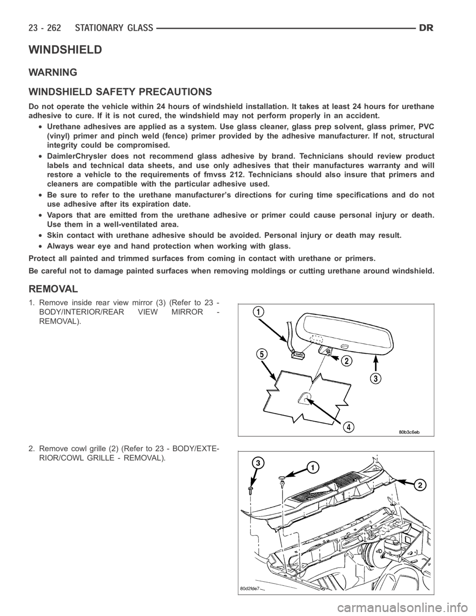
1. Remove inside rear view mirror (3) (Refer to 23 -
BODY/INTERIOR/REAR VIEW MIRROR -
REMOVAL).
2. Remove cowl grille (2) (Refer to 23 - BODY/EXTE-
RIOR/COWL GRILLE - REMOVAL).