2006 DODGE RAM SRT-10 ESP
[x] Cancel search: ESPPage 5061 of 5267
ACTUATOR-BLEND DOOR
DESCRIPTION
The blend door actuators are reversible, 12-volt direct
current (DC), servo motors. Models with the single
zone heating-A/C system have a single blend-air door,
which is controlled by a single blend door actuator.
Models with the dual zone system have two blend-air
doors, which are controlled by two blend door actua-
tors.
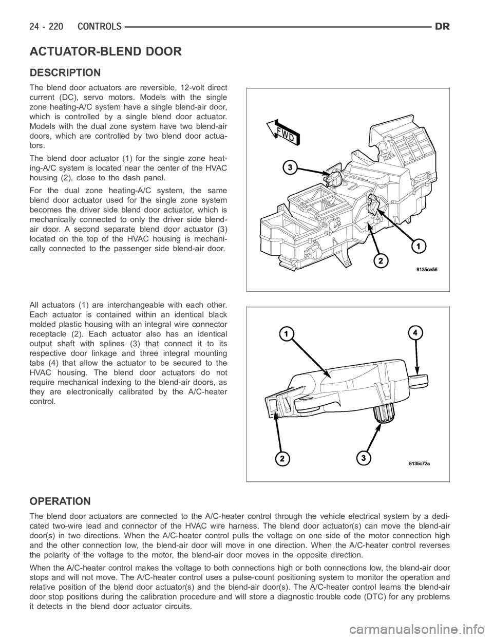
The blend door actuator (1) for the single zone heat-
ing-A/C system is located near the center of the HVAC
housing (2), close to the dash panel.
For the dual zone heating-A/C system, the same
blend door actuator used for the single zone system
becomes the driver side blend door actuator, which is
mechanically connected to only the driver side blend-
air door. A second separate blend door actuator (3)
located on the top of the HVAC housing is mechani-
cally connected to the passenger side blend-air door.
All actuators (1) are interchangeable with each other.
Each actuator is contained within an identical black
molded plastic housing with an integral wire connector
receptacle (2). Each actuator also has an identical
output shaft with splines (3) that connect it to its
respective door linkage and three integral mounting
tabs (4) that allow the actuator to be secured to the
HVAC housing. The blend door actuators do not
require mechanical indexing to the blend-air doors, as
they are electronically calibrated by the A/C-heater
control.
OPERATION
The blend door actuators are connected to the A/C-heater control through the vehicle electrical system by a dedi-
cated two-wire lead and connector of the HVAC wire harness. The blend door actuator(s) can move the blend-air
door(s) in two directions. When the A/C-heater control pulls the voltage on one side of the motor connection high
and the other connection low, the blend-air door will move in one direction. When the A/C-heater control reverses
the polarity of the voltage to the motor, the blend-air door moves in the opposite direction.
When the A/C-heater control makes the voltage to both connections high or both connections low, the blend-air door
stops and will not move. The A/C-heater control uses a pulse-count positioning system to monitor the operation and
relative position of the blend door actuator(s) and the blend-air door(s). The A/C-heater control learns the blend-air
door stop positions during the calibration procedure and will store a diagnostic trouble code (DTC) for any problems
it detects in the blend door actuator circuits.
Page 5066 of 5267
ACTUATOR-MODE DOOR
DESCRIPTION
The mode door actuators are reversible, 12-volt direct
current (DC) servo motors.The heating-A/C systems
on this vehicle use two mode door actuators. One for
the panel/floor-air door and one for the defrost-air
door.
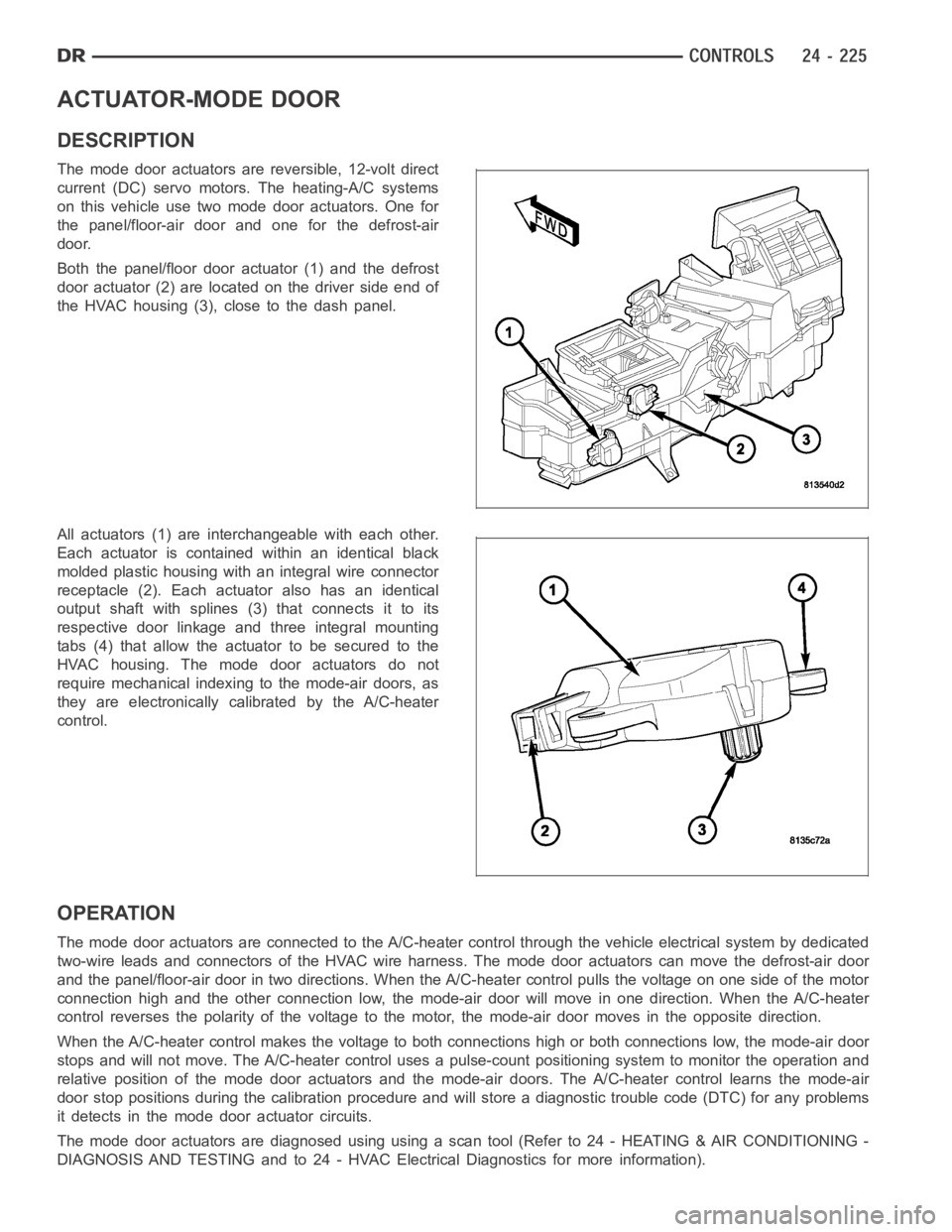
Both the panel/floor door actuator (1) and the defrost
door actuator (2) are located on the driver side end of
the HVAC housing (3), close to the dash panel.
All actuators (1) are interchangeable with each other.
Each actuator is contained within an identical black
molded plastic housing with an integral wire connector
receptacle (2). Each actuator also has an identical
output shaft with splines (3) that connects it to its
respective door linkage and three integral mounting
tabs (4) that allow the actuator to be secured to the
HVAC housing. The mode door actuators do not
require mechanical indexing to the mode-air doors, as
they are electronically calibrated by the A/C-heater
control.
OPERATION
The mode door actuators are connectedto the A/C-heater control through the vehicle electrical system by dedicated
two-wire leads and connectors of the HVAC wire harness. The mode door actuators can move the defrost-air door
and the panel/floor-air door in two directions. When the A/C-heater control pulls the voltage on one side of the motor
connection high and the other connection low, the mode-air door will move in one direction. When the A/C-heater
control reverses the polarity of the voltage to the motor, the mode-air door moves in the opposite direction.
When the A/C-heater control makes the voltage to both connections high or both connections low, the mode-air door
stops and will not move. The A/C-heater control uses a pulse-count positioning system to monitor the operation and
relative position of the mode door actuators and the mode-air doors. The A/C-heater control learns the mode-air
door stop positions during the calibration procedure and will store a diagnostic trouble code (DTC) for any problems
it detects in the mode door actuator circuits.
The mode door actuators are diagnosed using using a scan tool (Refer to 24 - HEATING & AIR CONDITIONING -
DIAGNOSIS AND TESTING and to 24 - HVAC Electrical Diagnostics for more information).
Page 5070 of 5267
ACTUATOR-RECIRCULATION DOOR
DESCRIPTION
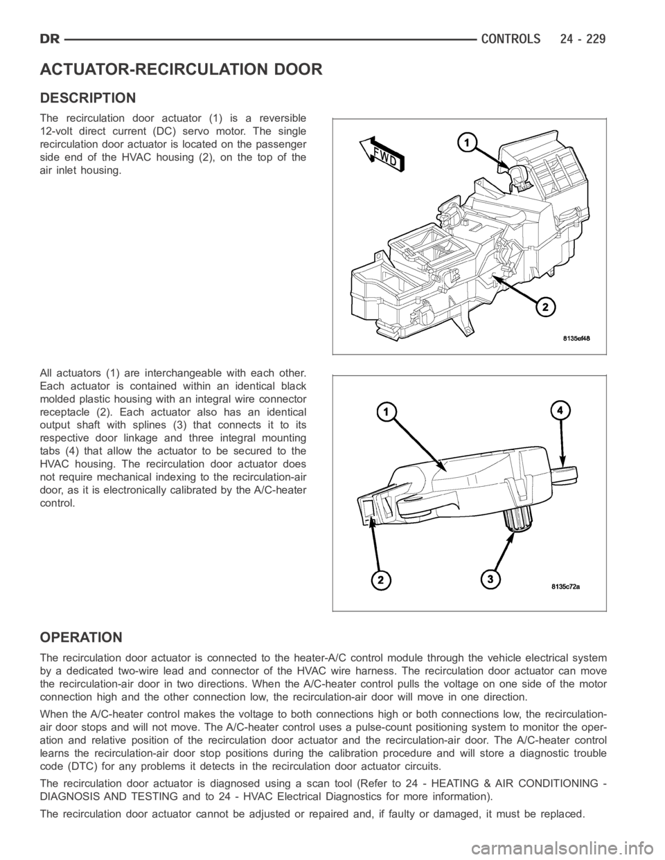
The recirculation door actuator (1) is a reversible
12-volt direct current (DC)servo motor. The single
recirculation door actuator is located on the passenger
side end of the HVAC housing (2), on the top of the
air inlet housing.
All actuators (1) are interchangeable with each other.
Each actuator is contained within an identical black
molded plastic housing with an integral wire connector
receptacle (2). Each actuator also has an identical
output shaft with splines (3) that connects it to its
respective door linkage and three integral mounting
tabs (4) that allow the actuator to be secured to the
HVAC housing. The recirculation door actuator does
not require mechanical indexing to the recirculation-air
door, as it is electronically calibrated by the A/C-heater
control.
OPERATION
The recirculation door actuator is connected to the heater-A/C control module through the vehicle electrical system
by a dedicated two-wire lead and connector of the HVAC wire harness. The recirculation door actuator can move
the recirculation-air door in two directions. When the A/C-heater control pulls the voltage on one side of the motor
connection high and the other connection low, the recirculation-air doorwill move in one direction.
When the A/C-heater control makes the voltage to both connections high or both connections low, the recirculation-
air door stops and will not move. The A/C-heater control uses a pulse-countpositioning system to monitor the oper-
ation and relative position of the recirculation door actuator and the recirculation-air door. The A/C-heater control
learns the recirculation-air door stop positions during the calibrationprocedure and will store a diagnostic trouble
code (DTC) for any problems it detects in the recirculation door actuator circuits.
The recirculation door actuator is diagnosed using a scan tool (Refer to 24- HEATING & AIR CONDITIONING -
DIAGNOSIS AND TESTING and to 24 - HVAC Electrical Diagnostics for more information).
The recirculation door actuator cannot be adjusted or repaired and, if faulty or damaged, it must be replaced.
Page 5089 of 5267
SENSOR-EVAPORATOR TEMPERATURE
DESCRIPTION
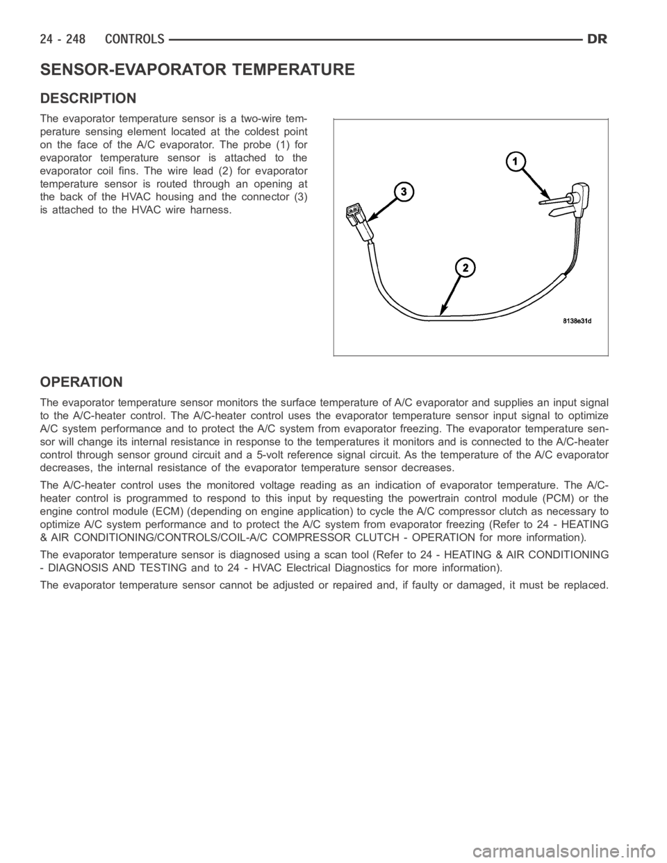
The evaporator temperature sensor is a two-wire tem-
perature sensing element located at the coldest point
on the face of the A/C evaporator. The probe (1) for
evaporator temperature sensor is attached to the
evaporator coil fins. The wire lead (2) for evaporator
temperature sensor is routed through an opening at
the back of the HVAC housing and the connector (3)
is attached to the HVAC wire harness.
OPERATION
The evaporator temperature sensor monitors the surface temperature of A/C evaporator and supplies an input signal
to the A/C-heater control. The A/C-heater control uses the evaporator temperature sensor input signal to optimize
A/C system performance and to protect the A/C system from evaporator freezing. The evaporator temperature sen-
sor will change its internal resistance in response to the temperatures itmonitors and is connected to the A/C-heater
control through sensor ground circuit and a 5-volt reference signal circuit. As the temperature of the A/C evaporator
decreases, the internal resistance of the evaporator temperature sensordecreases.
The A/C-heater control uses the monitored voltage reading as an indication of evaporator temperature. The A/C-
heater control is programmed to respond to this input by requesting the powertrain control module (PCM) or the
engine control module (ECM) (depending on engine application) to cycle the A/C compressor clutch as necessary to
optimize A/C system performance and to protect the A/C system from evaporatorfreezing(Referto24-HEATING
& AIR CONDITIONING/CONTROLS/COIL-A/C COMPRESSOR CLUTCH - OPERATION formore information).
The evaporator temperature sensor is diagnosed using a scan tool (Refer to24 - HEATING & AIR CONDITIONING
- DIAGNOSIS AND TESTING and to 24 - HVAC Electrical Diagnostics for more information).
The evaporator temperature sensor cannot be adjusted or repaired and, if faulty or damaged, it must be replaced.
Page 5092 of 5267

TRANSDUCER-A/C PRESSURE
DESCRIPTION
The A/C pressure transducer (1) is a switch that is
installed on a fitting located on the A/C discharge line.
An internally threaded fitting on the A/C pressure
transducer connects it to the externally threaded
Schrader-type fitting on the A/C discharge line. A rub-
ber O-ring seals the connection between the A/C pres-
sure transducer and the discharge line fitting. The A/C
pressure transducer is connected to the vehicle elec-
trical system by a molded plastic connector with three
terminals.
OPERATION
The A/C pressure transducer monitors the pressures in the high side of the refrigerant system through its connection
to a fitting on the A/C discharge line. The A/C pressure transducer will change its internal resistance in response to
the pressures it monitors. A Schrader-type valve in the A/C discharge linefitting permits the A/C pressure transducer
to be removed or installed without disturbing the refrigerant in the A/C system.
The A/C pressure transducer will change its internal resistance in response to the pressures it monitors. The pow-
ertrain control module (PCM) or the engine control module (ECM) (depending on engine application) provides a five
volt reference signal and a sensor ground to the A/C pressure transducer, then monitors the output voltage of the
transducer on a sensor return circuit to determine refrigerant pressure.The PCM/ECM is programmed to respond to
this and other sensor inputs by controlling the operation of the A/C compressor clutch and the radiator cooling fan
to help optimize A/C system performance and to protect the system components from damage. The PCM will dis-
engagetheA/Ccompressorclutchwhenhighsidepressurerisesabove3172kPa (460 psi) and re-engage the
clutch when high side pressure drops below 1999 kPa (290 psi). The A/C pressure transducer will also disengage
the A/C compressor clutch if the high side pressure drops below 193 kPa (28 psi) and will re-engage the clutch
when the high side pressure rises above 234 kPa (34 psi). If the refrigerantpressure rises above 1655 kPa (240
psi), the PCM will actuate the cooling fan. The A/C pressure transducer signal to the PCM/ECM will also prevent the
A/C compressor clutch from engaging when ambient temperatures are below about 10° C (50° F) due to the pres-
sure/temperature relationship of the refrigerant. The A/C pressure transducer input to the PCM/ECM will also pre-
vent the A/C compressor clutch from engaging when ambient temperatures are below about 10° C (50° F) due to
the pressure/temperature relationship of the refrigerant.
The A/C pressure transducer is diagnosed using a scan tool. Refer to 9 - Engine Electrical Diagnostics for more
information.
The A/C pressure transducer cannot be adjusted or repaired and, if faulty or damaged, it must be replaced.
REMOVAL
NOTE: It is not necessary to discharge the refrigerant system to replace the A/C pressure transducer.
Page 5093 of 5267
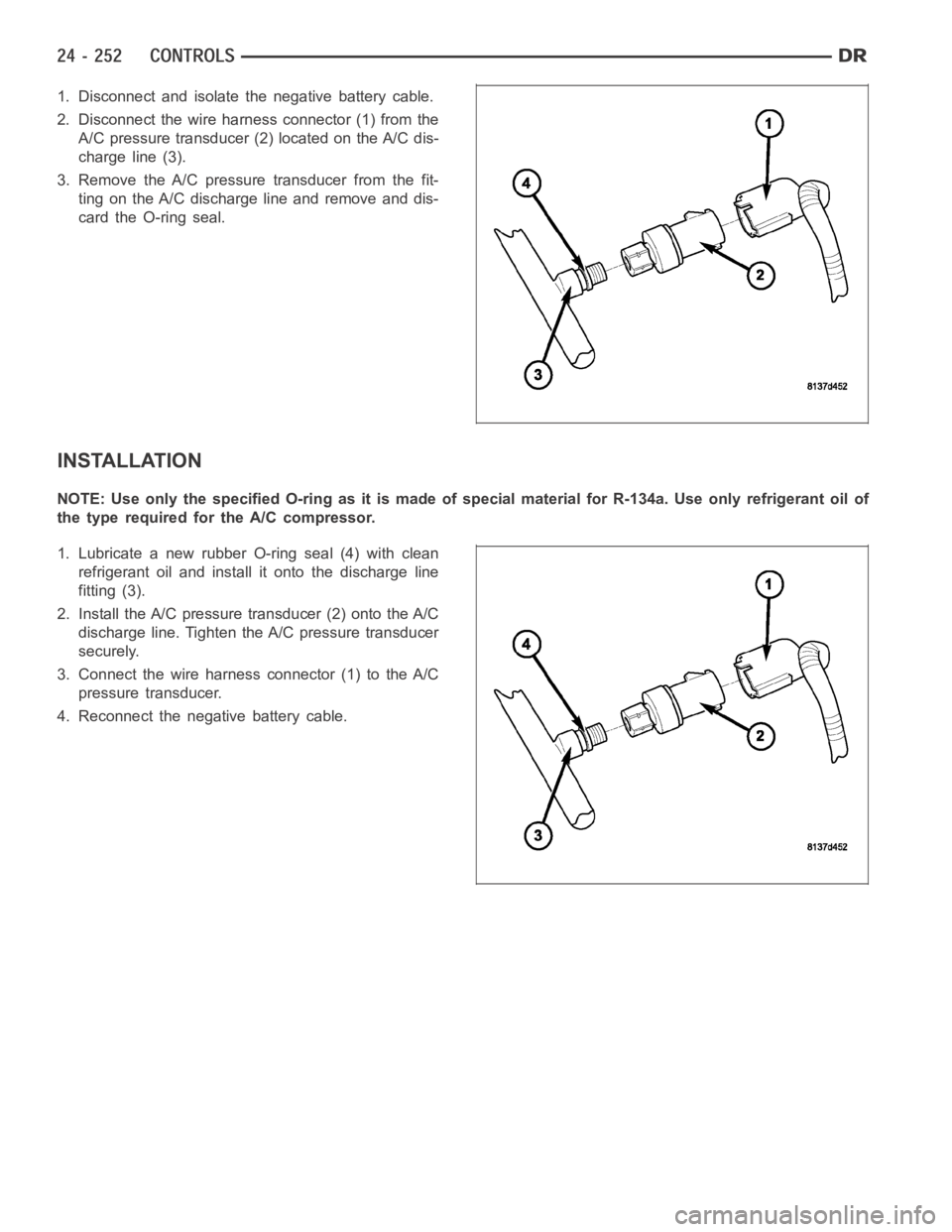
1. Disconnect and isolate the negative battery cable.
2. Disconnect the wire harness connector (1) from the
A/C pressure transducer (2) located on the A/C dis-
charge line (3).
3. Remove the A/C pressure transducer from the fit-
ting on the A/C discharge line and remove and dis-
card the O-ring seal.
INSTALLATION
NOTE:UseonlythespecifiedO-ringasitismadeofspecialmaterialforR-134a. Use only refrigerant oil of
the type required for the A/C compressor.
1. Lubricate a new rubber O-ring seal (4) with clean
refrigerant oil and install it onto the discharge line
fitting (3).
2. Install the A/C pressure transducer (2) onto the A/C
discharge line. Tighten the A/C pressure transducer
securely.
3. Connect the wire harness connector (1) to the A/C
pressure transducer.
4. Reconnect the negative battery cable.
Page 5131 of 5267
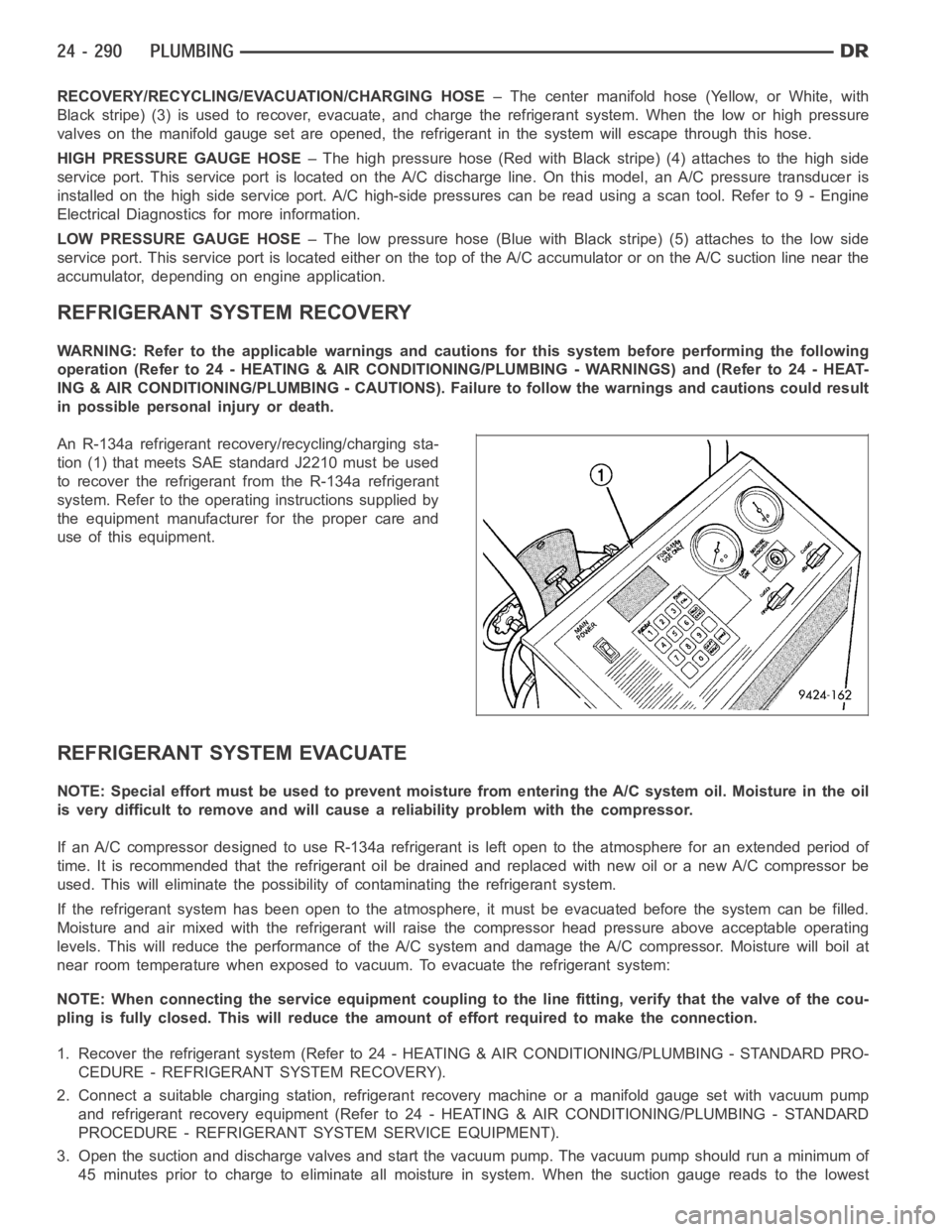
RECOVERY/RECYCLING/EVACUATION/CHARGING HOSE– The center manifold hose (Yellow, or White, with
Black stripe) (3) is used to recover, evacuate, and charge the refrigerantsystem. When the low or high pressure
valves on the manifold gauge set are opened, the refrigerant in the system will escape through this hose.
HIGH PRESSURE GAUGE HOSE– The high pressure hose (Red with Black stripe) (4) attaches to the high side
service port. This service port is located on the A/C discharge line. On this model, an A/C pressure transducer is
installed on the high side service port. A/C high-side pressures can be read using a scan tool. Refer to 9 - Engine
Electrical Diagnostics for more information.
LOW PRESSURE GAUGE HOSE– The low pressure hose (Blue with Black stripe) (5) attaches to the low side
service port. This service port is located either on the top of the A/C accumulator or on the A/C suction line near the
accumulator, depending on engine application.
REFRIGERANT SYSTEM RECOVERY
WARNING: Refer to the applicable warnings and cautions for this system before performing the following
operation (Refer to 24 - HEATING & AIR CONDITIONING/PLUMBING - WARNINGS) and (Refer to 24 - HEAT-
ING & AIR CONDITIONING/PLUMBING - CAUTIONS). Failure to follow the warnings and cautions could result
in possible personal injury or death.
An R-134a refrigerant recovery/recycling/charging sta-
tion (1) that meets SAE standard J2210 must be used
to recover the refrigerant from the R-134a refrigerant
system. Refer to the operating instructions supplied by
the equipment manufacturer for the proper care and
use of this equipment.
REFRIGERANT SYSTEM EVACUATE
NOTE: Special effort must be used to prevent moisture from entering the A/Csystem oil. Moisture in the oil
is very difficult to remove and will cause a reliability problem with the compressor.
If an A/C compressor designed to use R-134a refrigerant is left open to the atmosphere for an extended period of
time. It is recommended that the refrigerant oil be drained and replaced with new oil or a new A/C compressor be
used. This will eliminate the possibility of contaminating the refrigerant system.
If the refrigerant system has been open to the atmosphere, it must be evacuated before the system can be filled.
Moisture and air mixed with the refrigerant will raise the compressor headpressure above acceptable operating
levels. This will reduce the performance of the A/C system and damage the A/C compressor. Moisture will boil at
near room temperature when exposed to vacuum. To evacuate the refrigerantsystem:
NOTE: When connecting the service equipment coupling to the line fitting,verify that the valve of the cou-
pling is fully closed. This will reduce the amount of effort required to make the connection.
1. Recover the refrigerant system (Refer to 24 - HEATING & AIR CONDITIONING/PLUMBING - STANDARD PRO-
CEDURE - REFRIGERANT SYSTEM RECOVERY).
2. Connect a suitable charging station, refrigerant recovery machine or amanifold gauge set with vacuum pump
and refrigerant recovery equipment (Refer to 24 - HEATING & AIR CONDITIONING/PLUMBING - STANDARD
PROCEDURE - REFRIGERANT SYSTEM SERVICE EQUIPMENT).
3. Open the suction and discharge valves and start the vacuum pump. The vacuum pump should run a minimum of
45minutespriortochargetoeliminateall moisture in system. When the suction gauge reads to the lowest
Page 5149 of 5267
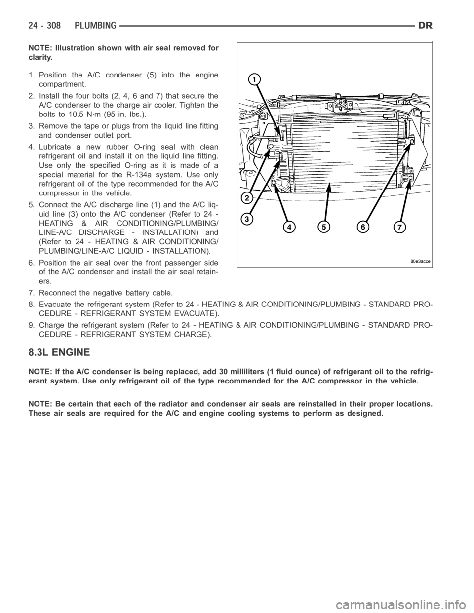
NOTE: Illustration shown with air seal removed for
clarity.
1. Position the A/C condenser (5) into the engine
compartment.
2. Install the four bolts (2, 4, 6 and 7) that secure the
A/C condenser to the charge air cooler. Tighten the
bolts to 10.5 Nꞏm (95 in. lbs.).
3. Remove the tape or plugs from the liquid line fitting
and condenser outlet port.
4. Lubricate a new rubber O-ring seal with clean
refrigerant oil and install it on the liquid line fitting.
UseonlythespecifiedO-ringasitismadeofa
special material for the R-134a system. Use only
refrigerant oil of the type recommended for the A/C
compressor in the vehicle.
5. Connect the A/C discharge line (1) and the A/C liq-
uid line (3) onto the A/C condenser (Refer to 24 -
HEATING & AIR CONDITIONING/PLUMBING/
LINE-A/C DISCHARGE - INSTALLATION) and
(Refer to 24 - HEATING & AIR CONDITIONING/
PLUMBING/LINE-A/C LIQUID - INSTALLATION).
6. Position the air seal over the front passenger side
of the A/C condenser and install the air seal retain-
ers.
7. Reconnect the negative battery cable.
8. Evacuate the refrigerant system (Refer to 24 - HEATING & AIR CONDITIONING/PLUMBING - STANDARD PRO-
CEDURE - REFRIGERANT SYSTEM EVACUATE).
9. Charge the refrigerant system (Refer to 24 - HEATING & AIR CONDITIONING/PLUMBING - STANDARD PRO-
CEDURE - REFRIGERANT SYSTEM CHARGE).
8.3L ENGINE
NOTE: If the A/C condenser is being replaced, add 30 milliliters (1 fluid ounce) of refrigerant oil to the refrig-
erant system. Use only refrigerant oil of the type recommended for the A/C compressor in the vehicle.
NOTE: Be certain that each of the radiator and condenser air seals are reinstalled in their proper locations.
These air seals are required for the A/C and engine cooling systems to perform as designed.