2006 DODGE RAM SRT-10 service
[x] Cancel search: servicePage 1723 of 5267
OIL
STANDARD PROCEDURE - ENGINE OIL SERVICE
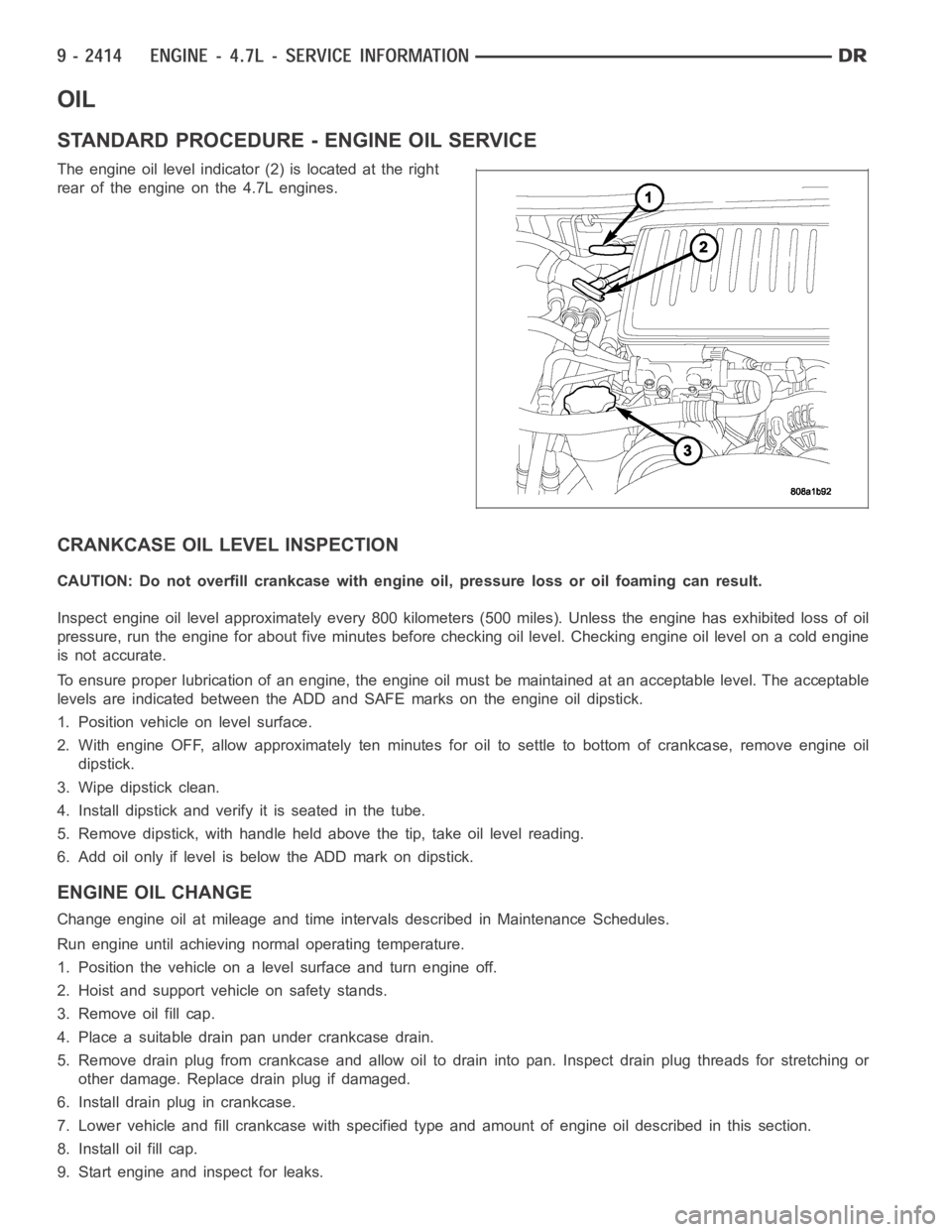
The engine oil level indicator (2) is located at the right
rear of the engine on the 4.7L engines.
CRANKCASE OIL LEVEL INSPECTION
CAUTION: Do not overfill crankcase with engine oil, pressure loss or oil foaming can result.
Inspect engine oil level approximately every 800 kilometers (500 miles).Unless the engine has exhibited loss of oil
pressure, run the engine for about five minutes before checking oil level.Checking engine oil level on a cold engine
is not accurate.
To ensure proper lubrication of an engine, the engine oil must be maintained at an acceptable level. The acceptable
levels are indicated between the ADD and SAFE marks on the engine oil dipstick.
1. Position vehicle on level surface.
2. With engine OFF, allow approximately ten minutes for oil to settle to bottom of crankcase, remove engine oil
dipstick.
3. Wipe dipstick clean.
4. Install dipstick and verify it is seated in the tube.
5. Remove dipstick, with handle held above the tip, take oil level reading.
6. Add oil only if level is below the ADD mark on dipstick.
ENGINE OIL CHANGE
Change engine oil at mileage and time intervals described in Maintenance Schedules.
Run engine until achieving normal operating temperature.
1. Position the vehicle on a level surface and turn engine off.
2. Hoist and support vehicle on safety stands.
3. Remove oil fill cap.
4. Place a suitable drain pan under crankcase drain.
5. Remove drain plug from crankcase and allow oil to drain into pan. Inspectdrain plug threads for stretching or
other damage. Replace drain plug if damaged.
6. Install drain plug in crankcase.
7. Lower vehicle and fill crankcase with specified type and amount of engine oil described in this section.
8. Install oil fill cap.
9. Start engine and inspect for leaks.
Page 1739 of 5267
VALVE TIMING
DESCRIPTION - TIMING DRIVE SYSTEM
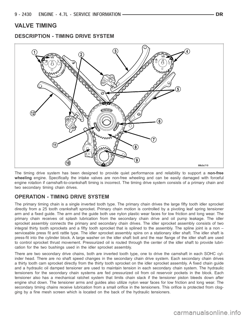
The timing drive system has been designed to provide quiet performance andreliability to support anon-free
wheelingengine. Specifically the intake valves are non-free wheeling and can be easily damaged with forceful
engine rotation if camshaft-to-crankshaft timing is incorrect. The timing drive system consists of a primary chain and
two secondary timing chain drives.
OPERATION - TIMING DRIVE SYSTEM
The primary timing chain is a single inverted tooth type. The primary chaindrives the large fifty tooth idler sprocket
directly from a 25 tooth crankshaft sprocket. Primary chain motion is controlled by a pivoting leaf spring tensioner
arm and a fixed guide. The arm and the guide both use nylon plastic wear facesfor low friction and long wear. The
primary chain receives oil splash lubrication from the secondary chain drive and oil pump leakage. The idler
sprocket assembly connects the primary and secondary chain drives. The idler sprocket assembly consists of two
integral thirty tooth sprockets and afifty tooth sprocket that is splinedto the assembly. The spline joint is a non –
serviceable press fit anti rattle type. The idler sprocket assembly spinson a stationary idler shaft. The idler shaft is
press-fit into the cylinder block. A large washer on the idler shaft bolt and the rear flange of the idler shaft are used
to control sprocket thrust movement. Pressurized oil is routed through the center of the idler shaft to provide lubri-
cation for the two bushings used in the idler sprocket assembly.
There are two secondary drive chains, both are inverted tooth type, one to drive the camshaft in each SOHC cyl-
inder head. There are no shaft speed changes in the secondary chain drive system. Each secondary chain drives
a thirty tooth cam sprocket directly from the thirty tooth sprocket on the idler sprocket assembly. A fixed chain guide
and a hydraulic oil damped tensioner are used to maintain tension in each secondary chain system. The hydraulic
tensioners for the secondary chainsystems are fed pressurized oil from oil reservoir pockets in the block. Each
tensioner also has a mechanical ratchet system that limits chain slack if the tensioner piston bleeds down after
engine shut down. The tensioner arms and guides also utilize nylon wear faces for low friction and long wear. The
secondary timing chains receive lubrication from a small orifice in the tensioners. This orifice is protected from clog-
ging by a fine mesh screen which is located on the back of the hydraulic tensioners.
Page 1745 of 5267
COVER - TIMING
REMOVAL
1. Disconnect the battery negative cable.
2. Drain cooling system (Refer to 7 - COOLING -
STANDARD PROCEDURE).
3. Disconnect both heater hoses at timing cover.
4. Disconnect lower radiator hose at engine.
5. Remove crankshaft damper (Refer to 9 - ENGINE/
ENGINE BLOCK/VIBRATION DAMPER -
REMOVAL).
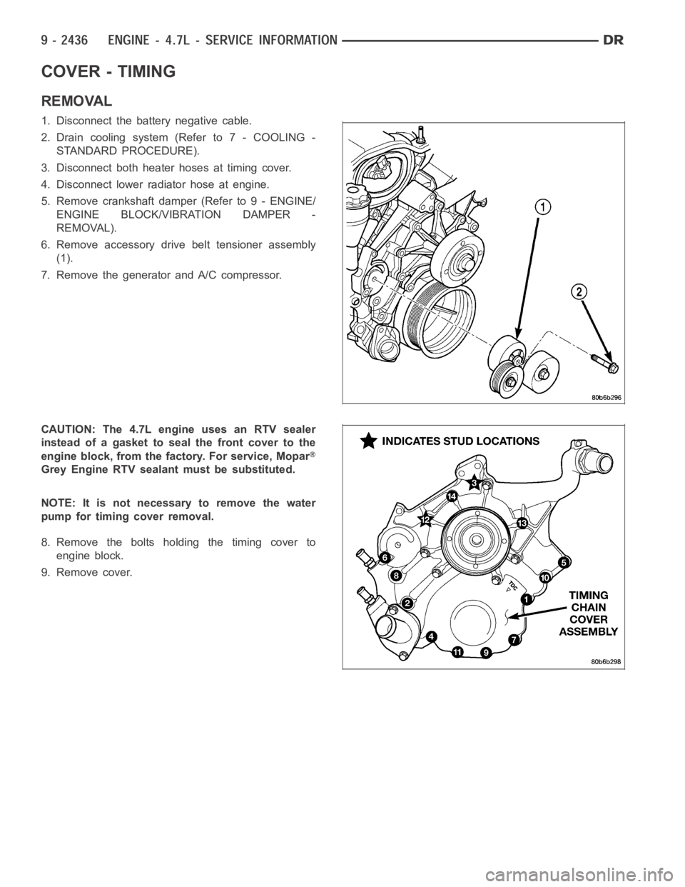
6. Remove accessory drive belt tensioner assembly
(1).
7. Remove the generator and A/C compressor.
CAUTION:The4.7LengineusesanRTVsealer
instead of a gasket to seal the front cover to the
engine block, from the factory. For service, Mopar
Grey Engine RTV sealant must be substituted.
NOTE: It is not necessary to remove the water
pump for timing cover removal.
8. Remove the bolts holding the timing cover to
engine block.
9. Remove cover.
Page 1746 of 5267
INSTALLATION
CAUTION: Do not use oil based liquids to clean
timing cover or block surfaces. Use only rubbing
alcohol, along with plastic or wooden scrapers.
Use no wire brushes or abrasive wheels or metal
scrapers, or damage to surfaces could result.
1. Clean timing chain cover and block surface using
rubbing alcohol.
CAUTION: The 4.7L can use a special RTV sealer
instead of a carrier gasket to seal the timing cover
to the engine block, from the factory. For service
repairs, Mopar
Grey Engine RTV must be used as
a substitute, if RTV is present. If the front cover
being used has no provisions for the water pas-
sage o-rings, then Mopar
Grey Engine RTV must
be applied around the water passages.
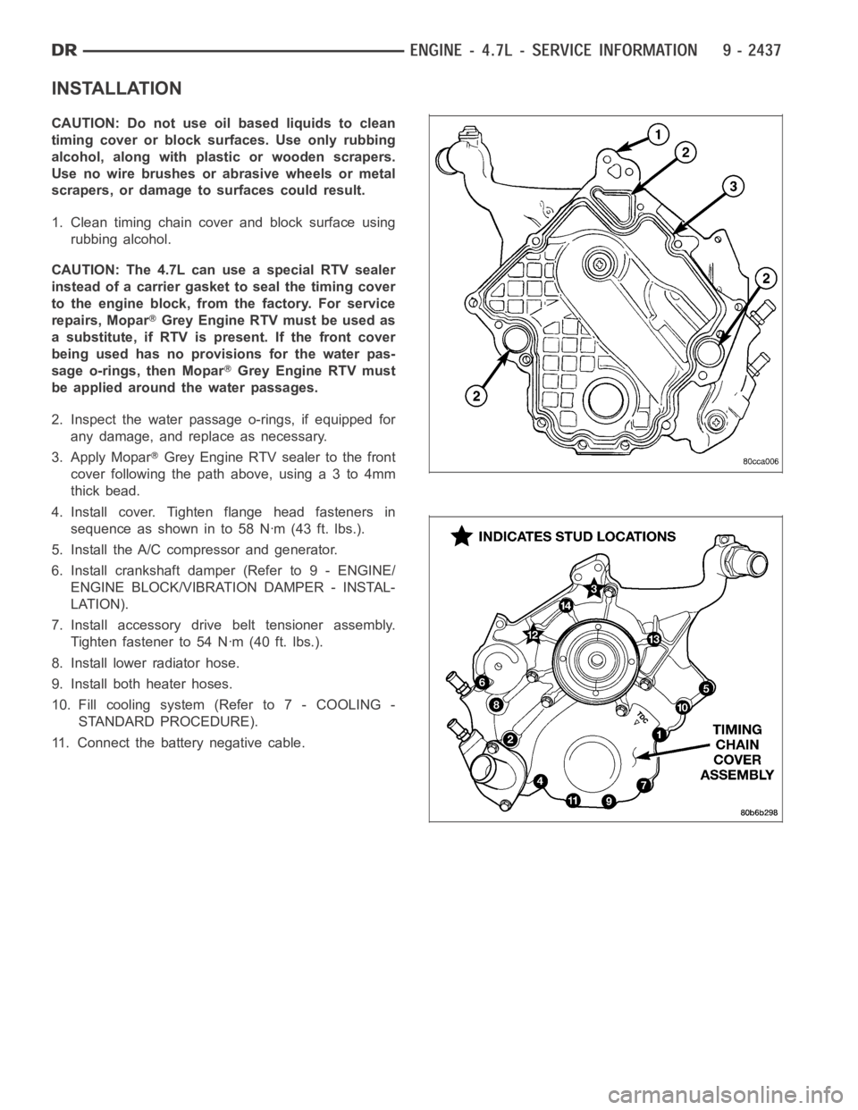
2. Inspect the water passage o-rings, if equipped for
any damage, and replace as necessary.
3. Apply Mopar
Grey Engine RTV sealer to the front
cover following the path above, using a 3 to 4mm
thick bead.
4. Install cover. Tighten flange head fasteners in
sequence as shown in to 58 Nꞏm (43 ft. lbs.).
5. Install the A/C compressor and generator.
6. Install crankshaft damper (Refer to 9 - ENGINE/
ENGINE BLOCK/VIBRATION DAMPER - INSTAL-
LATION).
7. Install accessory drive belt tensioner assembly.
Tighten fastener to 54 Nꞏm (40 ft. lbs.).
8. Install lower radiator hose.
9. Install both heater hoses.
10. Fill cooling system (Refer to 7 - COOLING -
STANDARD PROCEDURE).
11. Connect the battery negative cable.
Page 1756 of 5267
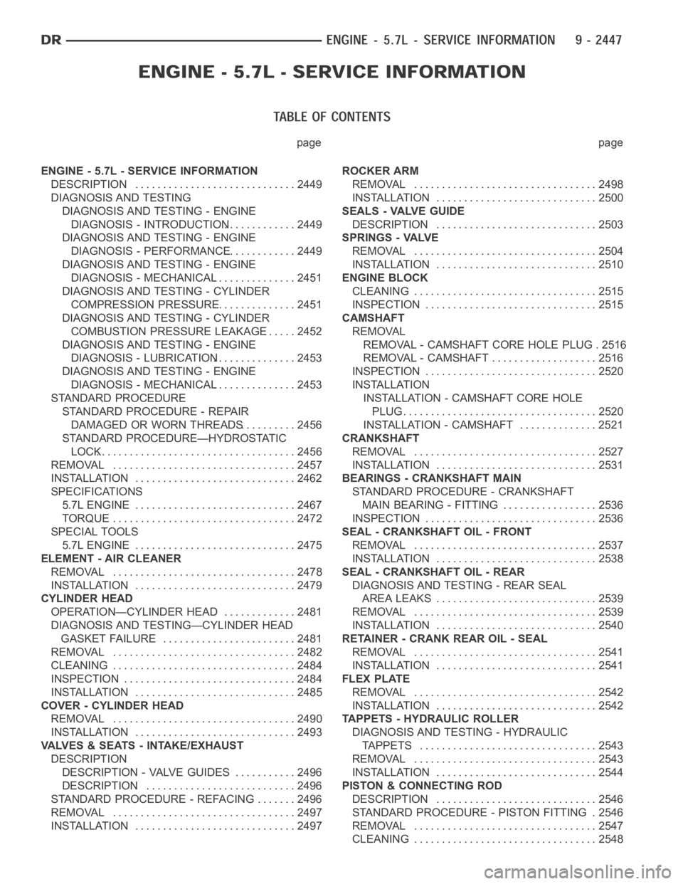
page page
ENGINE - 5.7L - SERVICE INFORMATION
DESCRIPTION ............................. 2449
DIAGNOSIS AND TESTING
DIAGNOSIS AND TESTING - ENGINE
DIAGNOSIS - INTRODUCTION............. 2449
DIAGNOSIS AND TESTING - ENGINE
DIAGNOSIS - PERFORMANCE............. 2449
DIAGNOSIS AND TESTING - ENGINE
DIAGNOSIS - MECHANICAL............... 2451
DIAGNOSIS AND TESTING - CYLINDER
COMPRESSION PRESSURE............... 2451
DIAGNOSIS AND TESTING - CYLINDER
COMBUSTION PRESSURE LEAKAGE...... 2452
DIAGNOSIS AND TESTING - ENGINE
DIAGNOSIS - LUBRICATION............... 2453
DIAGNOSIS AND TESTING - ENGINE
DIAGNOSIS - MECHANICAL............... 2453
STANDARD PROCEDURE
STANDARD PROCEDURE - REPAIR
DAMAGED OR WORN THREADS.......... 2456
STANDARD PROCEDURE—HYDROSTATIC
LOCK.................................... 2456
REMOVAL ................................. 2457
INSTALLATION ............................. 2462
SPECIFICATIONS
5.7L ENGINE ............................. 2467
TORQUE ................................. 2472
SPECIAL TOOLS
5.7L ENGINE ............................. 2475
ELEMENT - AIR CLEANER
REMOVAL ................................. 2478
INSTALLATION ............................. 2479
CYLINDER HEAD
OPERATION—CYLINDER HEAD ............. 2481
DIAGNOSIS AND TESTING—CYLINDER HEAD
GASKET FAILURE........................ 2481
REMOVAL ................................. 2482
CLEANING ................................. 2484
INSPECTION ............................... 2484
INSTALLATION ............................. 2485
COVER - CYLINDER HEAD
REMOVAL ................................. 2490
INSTALLATION ............................. 2493
VALVES & SEATS - INTAKE/EXHAUST
DESCRIPTION
DESCRIPTION - VALVE GUIDES ........... 2496
DESCRIPTION ........................... 2496
STANDARD PROCEDURE - REFACING ....... 2496
REMOVAL ................................. 2497
INSTALLATION ............................. 2497ROCKER ARM
REMOVAL ................................. 2498
INSTALLATION ............................. 2500
SEALS - VALVE GUIDE
DESCRIPTION ............................. 2503
SPRINGS - VALVE
REMOVAL ................................. 2504
INSTALLATION ............................. 2510
ENGINE BLOCK
CLEANING ................................. 2515
INSPECTION............................... 2515
CAMSHAFT
REMOVAL
REMOVAL - CAMSHAFT CORE HOLE PLUG . 2516
REMOVAL - CAMSHAFT ................... 2516
INSPECTION............................... 2520
INSTALLATION
INSTALLATION - CAMSHAFT CORE HOLE
PLUG.................................... 2520
INSTALLATION - CAMSHAFT .............. 2521
CRANKSHAFT
REMOVAL ................................. 2527
INSTALLATION ............................. 2531
BEARINGS - CRANKSHAFT MAIN
STANDARD PROCEDURE - CRANKSHAFT
MAIN BEARING - FITTING ................. 2536
INSPECTION............................... 2536
SEAL - CRANKSHAFT OIL - FRONT
REMOVAL ................................. 2537
INSTALLATION ............................. 2538
SEAL - CRANKSHAFT OIL - REAR
DIAGNOSIS AND TESTING - REAR SEAL
AREA LEAKS . ............................ 2539
REMOVAL ................................. 2539
INSTALLATION ............................. 2540
RETAINER - CRANK REAR OIL - SEAL
REMOVAL ................................. 2541
INSTALLATION ............................. 2541
FLEX PLATE
REMOVAL ................................. 2542
INSTALLATION ............................. 2542
TAPPETS - HYDRAULIC ROLLER
DIAGNOSIS AND TESTING - HYDRAULIC
TAPPETS ................................ 2543
REMOVAL ................................. 2543
INSTALLATION ............................. 2544
PISTON & CONNECTING ROD
DESCRIPTION ............................. 2546
STANDARD PROCEDURE - PISTON FITTING . 2546
REMOVAL ................................. 2547
CLEANING ................................. 2548
Page 1757 of 5267
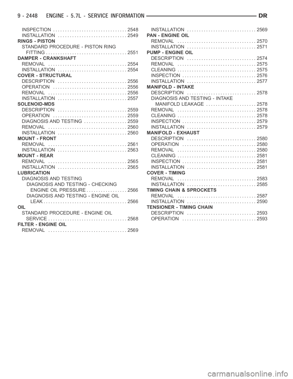
INSPECTION ............................... 2548
INSTALLATION ............................. 2549
RINGS - PISTON
STANDARD PROCEDURE - PISTON RING
FITTING .................................. 2551
DAMPER - CRANKSHAFT
REMOVAL ................................. 2554
INSTALLATION ............................. 2554
COVER - STRUCTURAL
DESCRIPTION ............................. 2556
OPERATION ............................... 2556
REMOVAL ................................. 2556
INSTALLATION ............................. 2557
SOLENOID-MDS
DESCRIPTION ............................. 2559
OPERATION ............................... 2559
DIAGNOSIS AND TESTING .................. 2559
REMOVAL ................................. 2560
INSTALLATION ............................. 2560
MOUNT - FRONT
REMOVAL ................................. 2561
INSTALLATION ............................. 2563
MOUNT - REAR
REMOVAL ................................. 2565
INSTALLATION ............................. 2565
LUBRICATION
DIAGNOSIS AND TESTING
DIAGNOSIS AND TESTING - CHECKING
ENGINE OIL PRESSURE.................. 2566
DIAGNOSIS AND TESTING - ENGINE OIL
LEAK.................................... 2566
OIL
STANDARD PROCEDURE - ENGINE OIL
SERVICE ................................. 2568
FILTER - ENGINE OIL
REMOVAL ................................. 2569INSTALLATION ............................. 2569
PA N - E N G I N E O I L
REMOVAL ................................. 2570
INSTALLATION ............................. 2571
PUMP - ENGINE OIL
DESCRIPTION ............................. 2574
REMOVAL ................................. 2575
CLEANING ................................. 2575
INSPECTION............................... 2576
INSTALLATION ............................. 2577
MANIFOLD - INTAKE
DESCRIPTION ............................. 2578
DIAGNOSIS AND TESTING - INTAKE
MANIFOLD LEAKAGE ..................... 2578
REMOVAL ................................. 2578
CLEANING ................................. 2578
INSPECTION............................... 2579
INSTALLATION ............................. 2579
MANIFOLD - EXHAUST
DESCRIPTION ............................. 2580
OPERATION ............................... 2580
REMOVAL ................................. 2580
CLEANING ................................. 2581
INSPECTION............................... 2581
INSTALLATION ............................. 2581
COVER - TIMING
REMOVAL ................................. 2583
INSTALLATION ............................. 2585
TIMING CHAIN & SPROCKETS
REMOVAL ................................. 2587
INSTALLATION ............................. 2590
TENSIONER - TIMING CHAIN
DESCRIPTION ............................. 2593
OPERATION ............................... 2593
Page 1758 of 5267
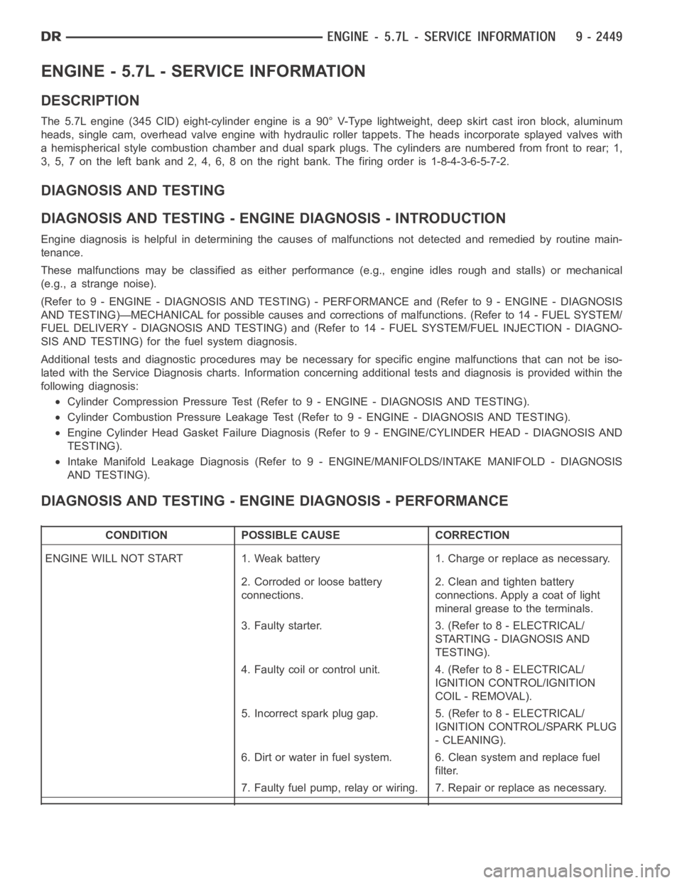
ENGINE - 5.7L - SERVICE INFORMATION
DESCRIPTION
The 5.7L engine (345 CID) eight-cylinder engine is a 90° V-Type lightweight, deep skirt cast iron block, aluminum
heads, single cam, overhead valve engine with hydraulic roller tappets. The heads incorporate splayed valves with
a hemispherical style combustion chamber and dual spark plugs. The cylinders are numbered from front to rear; 1,
3, 5, 7 on the left bank and 2, 4, 6, 8 on the right bank. The firing order is 1-8-4-3-6-5-7-2.
DIAGNOSIS AND TESTING
DIAGNOSIS AND TESTING - ENGINE DIAGNOSIS - INTRODUCTION
Engine diagnosis is helpful in determining the causes of malfunctions notdetected and remedied by routine main-
tenance.
These malfunctions may be classified as either performance (e.g., engineidles rough and stalls) or mechanical
(e.g., a strange noise).
(Refer to 9 - ENGINE - DIAGNOSIS AND TESTING) - PERFORMANCE and (Refer to 9 - ENGINE - DIAGNOSIS
AND TESTING)—MECHANICAL for possible causes and corrections of malfunctions. (Refer to 14 - FUEL SYSTEM/
FUEL DELIVERY - DIAGNOSIS AND TESTING) and (Refer to 14 - FUEL SYSTEM/FUEL INJECTION - DIAGNO-
SIS AND TESTING) for the fuel system diagnosis.
Additional tests and diagnostic procedures may be necessary for specificengine malfunctions that can not be iso-
lated with the Service Diagnosis charts. Information concerning additional tests and diagnosis is provided within the
following diagnosis:
Cylinder Compression Pressure Test (Refer to 9 - ENGINE - DIAGNOSIS AND TESTING).
Cylinder Combustion Pressure LeakageTest (Refer to 9 - ENGINE - DIAGNOSISAND TESTING).
Engine Cylinder Head Gasket Failure Diagnosis (Refer to 9 - ENGINE/CYLINDER HEAD - DIAGNOSIS AND
TESTING).
Intake Manifold Leakage Diagnosis (Refer to 9 - ENGINE/MANIFOLDS/INTAKEMANIFOLD - DIAGNOSIS
AND TESTING).
DIAGNOSIS AND TESTING - ENGINE DIAGNOSIS - PERFORMANCE
CONDITION POSSIBLE CAUSE CORRECTION
ENGINE WILL NOT START 1. Weak battery 1. Charge or replace as necessary.
2. Corroded or loose battery
connections.2. Clean and tighten battery
connections. Apply a coat of light
mineral grease to the terminals.
3. Faulty starter. 3. (Refer to 8 - ELECTRICAL/
STARTING - DIAGNOSIS AND
TESTING).
4. Faulty coil or control unit. 4. (Refer to 8 - ELECTRICAL/
IGNITION CONTROL/IGNITION
COIL - REMOVAL).
5. Incorrect spark plug gap. 5. (Refer to 8 - ELECTRICAL/
IGNITION CONTROL/SPARK PLUG
- CLEANING).
6. Dirt or water in fuel system. 6. Clean system and replace fuel
filter.
7. Faulty fuel pump, relay or wiring. 7. Repair or replace as necessary.
Page 1760 of 5267
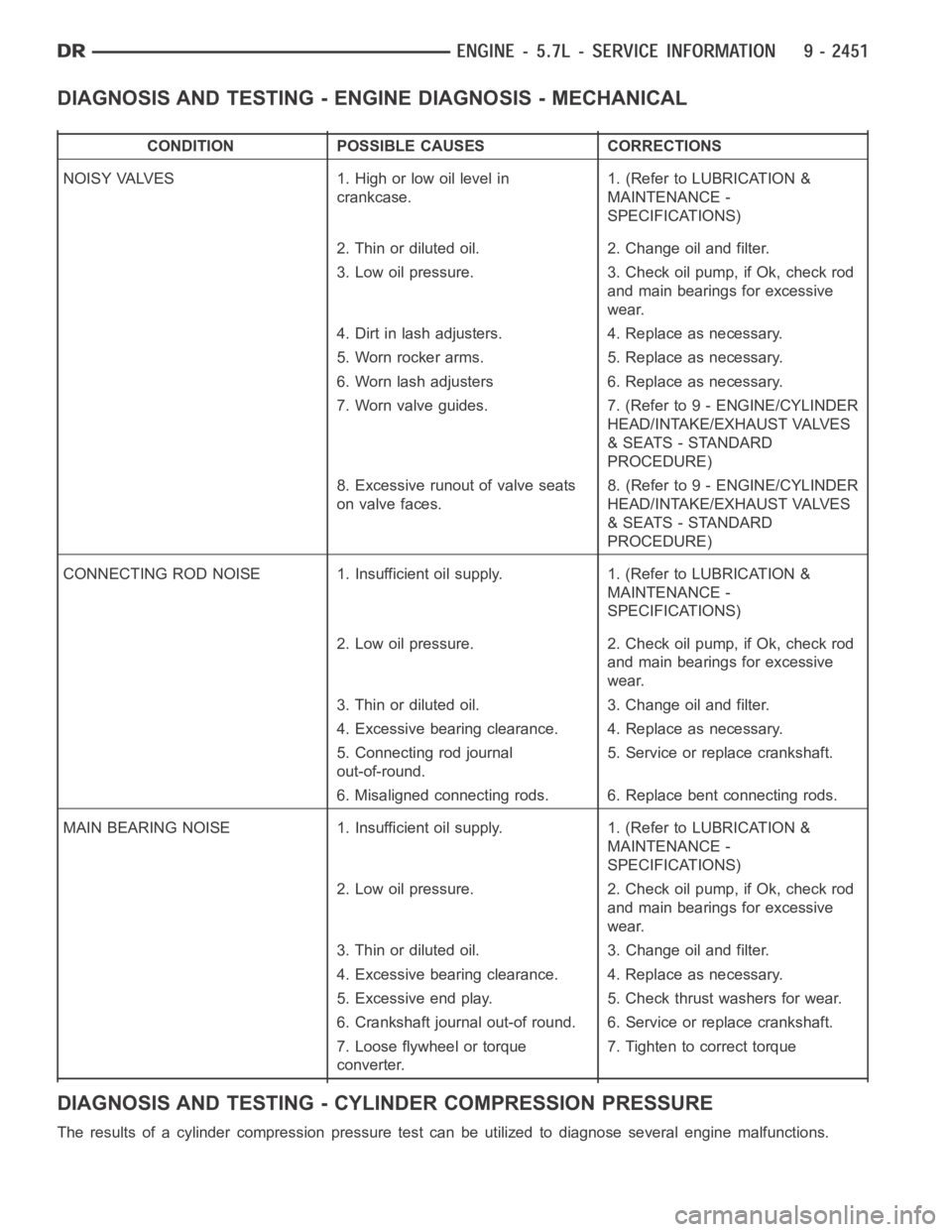
DIAGNOSIS AND TESTING - ENGINE DIAGNOSIS - MECHANICAL
CONDITION POSSIBLE CAUSES CORRECTIONS
NOISY VALVES 1. High or low oil level in
crankcase.1. (Refer to LUBRICATION &
MAINTENANCE -
SPECIFICATIONS)
2. Thin or diluted oil. 2. Change oil and filter.
3. Low oil pressure. 3. Check oil pump, if Ok, check rod
and main bearings for excessive
wear.
4. Dirt in lash adjusters. 4. Replace as necessary.
5. Worn rocker arms. 5. Replace as necessary.
6. Worn lash adjusters 6. Replace as necessary.
7. Worn valve guides. 7. (Refer to 9 - ENGINE/CYLINDER
HEAD/INTAKE/EXHAUST VALVES
& SEATS - STANDARD
PROCEDURE)
8. Excessive runout of valve seats
on valve faces.8. (Refer to 9 - ENGINE/CYLINDER
HEAD/INTAKE/EXHAUST VALVES
& SEATS - STANDARD
PROCEDURE)
CONNECTING ROD NOISE 1. Insufficient oil supply. 1. (Refer to LUBRICATION&
MAINTENANCE -
SPECIFICATIONS)
2. Low oil pressure. 2. Check oil pump, if Ok, check rod
and main bearings for excessive
wear.
3. Thin or diluted oil. 3. Change oil and filter.
4. Excessive bearing clearance. 4. Replace as necessary.
5. Connecting rod journal
out-of-round.5. Service or replace crankshaft.
6. Misaligned connecting rods. 6. Replace bent connecting rods.
MAIN BEARING NOISE 1. Insufficient oil supply. 1. (Refer to LUBRICATION &
MAINTENANCE -
SPECIFICATIONS)
2. Low oil pressure. 2. Check oil pump, if Ok, check rod
and main bearings for excessive
wear.
3. Thin or diluted oil. 3. Change oil and filter.
4. Excessive bearing clearance. 4. Replace as necessary.
5. Excessive end play. 5. Check thrust washers for wear.
6. Crankshaft journal out-of round. 6. Service or replace crankshaft.
7. Loose flywheel or torque
converter.7. Tighten to correct torque
DIAGNOSIS AND TESTING - CYLINDER COMPRESSION PRESSURE
The results of a cylinder compressionpressure test can be utilized to diagnose several engine malfunctions.