2006 DODGE RAM SRT-10 service
[x] Cancel search: servicePage 1653 of 5267
CYLINDER HEAD
DESCRIPTION
DESCRIPTION - CYLINDER HEAD
The cylinder heads are made of an aluminum alloy. The cylinder head features two valves per cylinder with pressed
in powdered metal valve guides. The cylinder heads also provide enclosures for the timing chain drain, necessitating
unique left and right cylinder heads.
DESCRIPTION - VALVE GUIDES
The valve guides are made of powered metal and are pressed into the cylinderhead. The guides are not replace-
able or serviceable, and valve guide reaming is not recommended. If the guides are worn beyond acceptable limits,
replace the cylinder heads.
DIAGNOSIS AND TESTING
CYLINDER HEAD GASKET
A cylinder head gasket leak can be located between adjacent cylinders or between a cylinder and the adjacent
water jacket.
Possible indications of the cylinder head gasket leaking between adjacent cylinders are:
Loss of engine power
Engine misfiring
Poor fuel economy
Possible indications of the cylinder head gasket leaking between a cylinder and an adjacent water jacket are:
Engine overheating
Loss of coolant
Excessive steam (white smoke) emitting from exhaust
Coolant foaming
CYLINDER-TO-CYLINDER LEAKAGE TEST
To determine if an engine cylinder head gasket is leaking between adjacentcylinders, follow the procedures in Cyl-
inder Compression Pressure Test (Refer to 9 - ENGINE - DIAGNOSIS AND TESTING). An engine cylinder head
gasket leaking between adjacent cylinders will result in approximately a50 - 70% reduction in compression pres-
sure.
CYLINDER-TO-WATER JACKET LEAKAGE TEST
WARNING: USE EXTREME CAUTION WHEN THE ENGINE IS OPERATING WITH COOLANT PRESSURE CAP
REMOVED.
VISUAL TEST METHOD
With the engine cool, remove the coolant pressure cap. Start the engine andallow it to warm up until thermostat
opens.
If a large combustion/compression pressure leak exists, bubbles will be visible in the coolant.
COOLING SYSTEM TESTER METHOD
WARNING: WITH COOLING SYSTEM TESTER IN PLACE, PRESSURE WILL BUILD UP FAST.EXCESSIVE
PRESSURE BUILT UP, BY CONTINUOUS ENGINE OPERATION, MUST BE RELEASED TO A SAFE PRESSURE
POINT. NEVER PERMIT PRESSURE TO EXCEED 138 kPa (20 psi).
Page 1659 of 5267
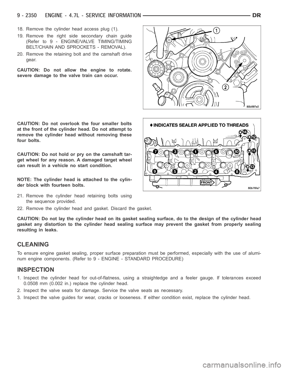
18. Remove the cylinder head access plug (1).
19. Remove the right side secondary chain guide
(Refer to 9 - ENGINE/VALVE TIMING/TIMING
BELT/CHAIN AND SPROCKETS - REMOVAL).
20. Remove the retaining bolt and the camshaft drive
gear.
CAUTION: Do not allow the engine to rotate.
severe damage to the valve train can occur.
CAUTION: Do not overlook the four smaller bolts
at the front of the cylinder head. Do not attempt to
remove the cylinder head without removing these
four bolts.
CAUTION: Do not hold or pry on the camshaft tar-
get wheel for any reason. A damaged target wheel
can result in a vehicle no start condition.
NOTE: The cylinder head is attached to the cylin-
der block with fourteen bolts.
21. Remove the cylinder head retaining bolts using
the sequence provided.
22. Remove the cylinder head and gasket. Discard the gasket.
CAUTION: Do not lay the cylinder head on its gasket sealing surface, do to the design of the cylinder head
gasket any distortion to the cylinder head sealing surface may prevent thegasket from properly sealing
resulting in leaks.
CLEANING
To ensure engine gasket sealing, proper surface preparation must be performed, especially with the use of alumi-
num engine components. (Refer to 9 - ENGINE - STANDARD PROCEDURE)
INSPECTION
1. Inspect the cylinder head for out-of-flatness, using a straightedge and a feeler gauge. If tolerances exceed
0.0508 mm (0.002 in.) replace the cylinder head.
2. Inspect the valve seats for damage. Service the valve seats as necessary.
3. Inspect the valve guides for wear, cracks or looseness. If either condition exist, replace the cylinder head.
Page 1692 of 5267
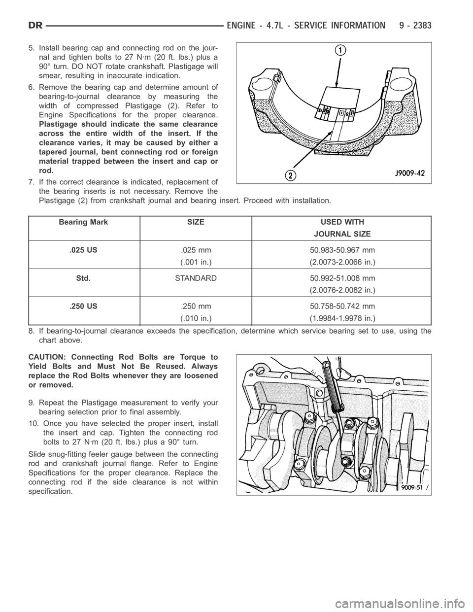
5. Install bearing cap and connecting rod on the jour-
nal and tighten bolts to 27 Nꞏm (20 ft. lbs.) plus a
90° turn. DO NOT rotate crankshaft. Plastigage will
smear, resulting in inaccurate indication.
6. Remove the bearing cap and determine amount of
bearing-to-journal clearance by measuring the
width of compressed Plastigage (2). Refer to
Engine Specifications for the proper clearance.
Plastigage should indicate the same clearance
across the entire width of the insert. If the
clearancevaries,itmaybecausedbyeithera
tapered journal, bent connecting rod or foreign
material trapped between the insert and cap or
rod.
7. If the correct clearance is indicated, replacement of
the bearing inserts is not necessary. Remove the
Plastigage (2) from crankshaft journal and bearing insert. Proceed with installation.
Bearing Mark SIZE USED WITH
JOURNAL SIZE
.025 US.025 mm 50.983-50.967 mm
(.001 in.) (2.0073-2.0066 in.)
Std.STANDARD 50.992-51.008 mm
(2.0076-2.0082 in.)
.250 US.250 mm 50.758-50.742 mm
(.010 in.) (1.9984-1.9978 in.)
8. If bearing-to-journal clearance exceeds the specification, determine which service bearing set to use, using the
chart above.
CAUTION: Connecting Rod Bolts are Torque to
Yield Bolts and Must Not Be Reused. Always
replace the Rod Bolts whenever they are loosened
or removed.
9. Repeat the Plastigage measurement to verify your
bearing selection prior to final assembly.
10. Once you have selected the proper insert, install
the insert and cap. Tighten the connecting rod
bolts to 27 Nꞏm (20 ft. lbs.) plus a 90° turn.
Slide snug-fitting feeler gauge between the connecting
rod and crankshaft journal flange. Refer to Engine
Specifications for the proper clearance. Replace the
connecting rod if the side clearance is not within
specification.
Page 1693 of 5267
PLUGS - CORE
REMOVAL
1. Drain the cooling system (Refer to 7 - COOLING -
STANDARD PROCEDURE).
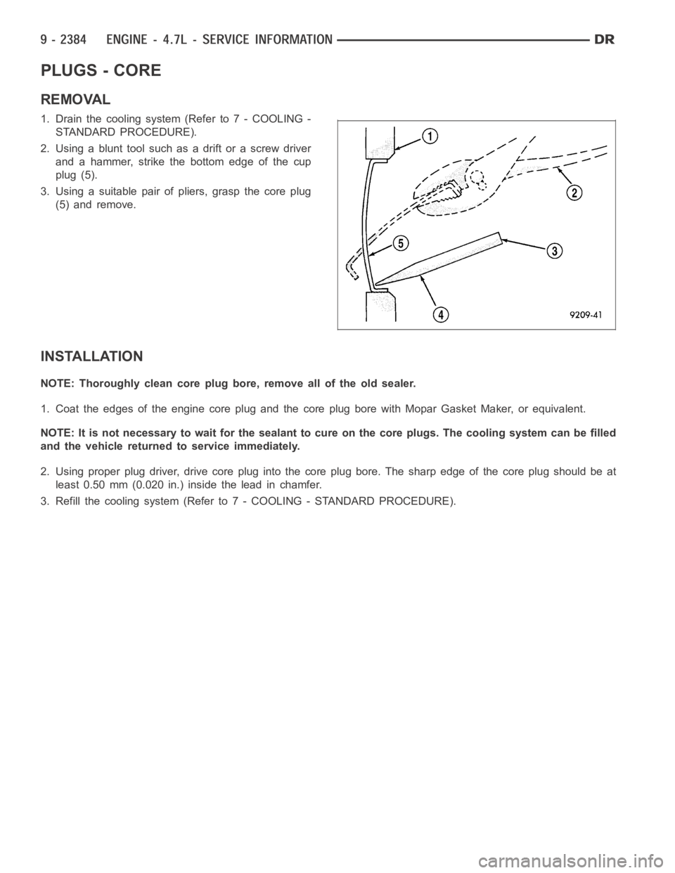
2. Using a blunt tool such as a drift or a screw driver
and a hammer, strike the bottom edge of the cup
plug (5).
3. Using a suitable pair of pliers, grasp the core plug
(5) and remove.
INSTALLATION
NOTE: Thoroughly clean core plug bore, remove all of the old sealer.
1. Coat the edges of the engine core plug and the core plug bore with Mopar Gasket Maker, or equivalent.
NOTE: It is not necessary to wait for the sealant to cure on the core plugs. The cooling system can be filled
and the vehicle returned to service immediately.
2. Using proper plug driver, drive core plug into the core plug bore. The sharp edge of the core plug should be at
least 0.50 mm (0.020 in.) inside the lead in chamfer.
3. Refill the cooling system (Refer to 7 - COOLING - STANDARD PROCEDURE).
Page 1695 of 5267
INSPECTION
NOTE: Thoroughly inspect the connecting rod bearing bores and main bearing bores for scoring, blueing or
severe scratches. Further disassembly may be required.
If connecting rod bearing bores show damage, the cylinder heads must be removed to service the piston and rod
assemblies. If the bedplate or the cylinder block main bearing bores show damage the engine must be replaced.
1. If required, remove the main bearing halves from the cylinder block and bedplate.
2. Thoroughly clean the bedplate to cylinder block sealing surfaces and main bearing bores. Remove all oil and
sealant residue.
3. Inspect the bedplate main bearing bores for cracks, scoring or severe blueing. If either condition exists the
engine must be replaced.
4. Inspect the crankshaft thrust washers for scoring, scratches, wear or blueing. If either condition exist replace the
thrust washer.
5. Inspect the oil pan gasket/windage tray for splits, tears or cracks in the gasket sealing surfaces. Replace gasket
as necessary.
INSTALLATION
CAUTION: Main bearings are select fit. (Refer to 9
- ENGINE/ENGINE BLOCK/CRANKSHAFT MAIN
BEARINGS - STANDARD PROCEDURE) for proper
bearing selections.
1. Lubricate upper main bearing halves with clean
engine oil.
CAUTION: When installing crankshaft, use care
not to damage bearing surfaces on the crankshaft.
2. Position crankshaft in cylinder block.
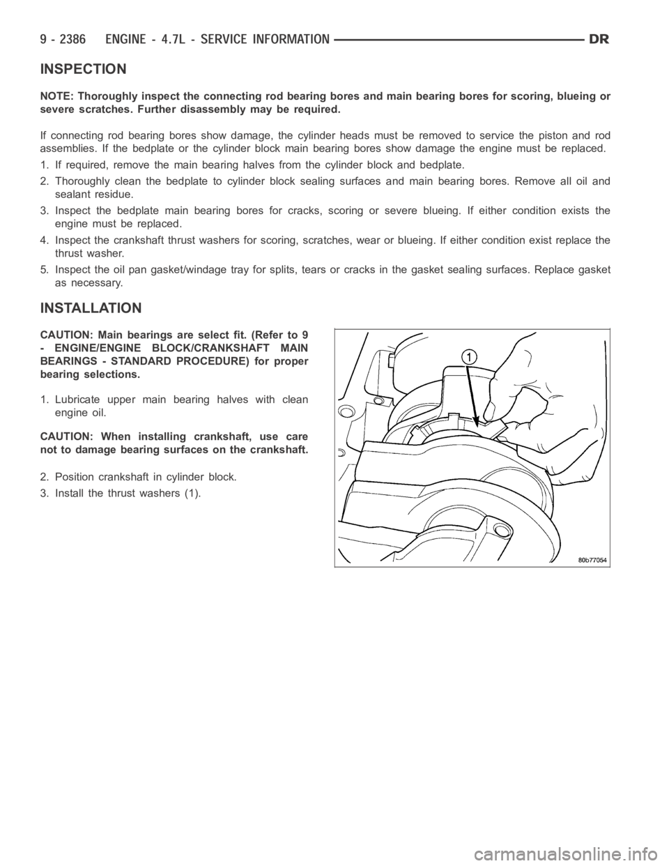
3. Install the thrust washers (1).
Page 1698 of 5267
BEARINGS - CRANKSHAFT MAIN
STANDARD PROCEDURE - CRANKSHAFT MAIN BEARING - FITTING
MAIN BEARING JOURNAL DIAMETER (CRANKSHAFT REMOVED)
Crankshaft removed from the cylinder block.
Clean the oil off the main bearing journal.
Determine the maximum diameter of the journal with a micrometer. Measure at two locations 90° apart at each end
of the journal.
The maximum allowable taper is 0.008mm (0.0004 inch.) and maximum out of round is 0.005mm (0.002 inch). Com-
pare the measured diameter with the journal diameter specification (MainBearing Fitting Chart). Select inserts
required to obtain the specified bearing-to-journal clearance.
CRANKSHAFT MAIN BEARING SELECTION
The main bearings are “select fit” to achieve proper oil
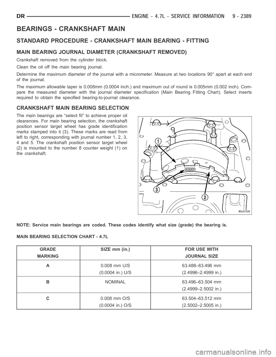
clearances. For main bearing selection, the crankshaft
position sensor target wheel has grade identification
marks stamped into it (3). These marks are read from
left to right, corresponding with journal number 1, 2, 3,
4 and 5. The crankshaft position sensor target wheel
(2) is mounted to the number 8 counter weight (1) on
the crankshaft.
NOTE: Service main bearings are coded. These codes identify what size (grade) the bearing is.
MAIN BEARING SELECTION CHART - 4.7L
GRADE SIZE mm (in.) FOR USE WITH
MARKING JOURNAL SIZE
A0.008 mm U/S 63.488–63.496 mm
(0.0004 in.) U/S (2.4996–2.4999 in.)
BNOMINAL 63.496–63.504 mm
(2.4999–2.5002 in.)
C0.008 mm O/S 63.504–63.512 mm
(0.0004 in.) O/S (2.5002–2.5005 in.)
Page 1705 of 5267
ROD - PISTON & CONNECTING
DESCRIPTION
CAUTION: Do not use a metal stamp to mark connecting rods as damage may result, instead use ink or a
scratch awl.
Thepistonsaremadeofahighstrengthaluminumalloy.Theanodizedtopring groove and crown has been
replaced with a coated top ring that is blue in color on the bottom surface. Piston skirts are coated with a solid
lubricant (Molykote) to reduce friction and provide scuff resistance. The connecting rods are made of forged pow-
dered metal, with a “fractured cap” design. A pressed fit piston pin is usedto attach the piston and connecting rod.
STANDARD PROCEDURE - PISTON FITTING
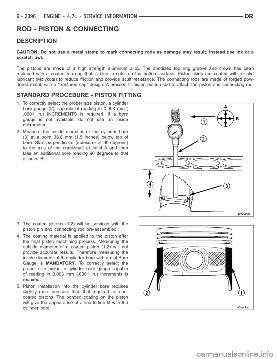
1. To correctly select the proper size piston, a cylinder
bore gauge (2), capable of reading in 0.003 mm (
.0001 in.) INCREMENTS is required. If a bore
gauge is not available, do not use an inside
micrometer.
2. Measure the inside diameter of the cylinder bore
(3) at a point 38.0 mm (1.5 inches) below top of
bore. Start perpendicular (across or at 90 degrees)
to the axis of the crankshaft at point A and then
take an additional bore reading 90 degrees to that
at point B.
3. The coated pistons (1,2) will be serviced with the
piston pin and connecting rod pre-assembled.
4. The coating material is applied to the piston after
the final piston machining process. Measuring the
outside diameter of a coated piston (1,2) will not
provide accurate results. Therefore measuring the
inside diameter of the cylinder bore with a dial Bore
Gauge isMANDATORY. To correctly select the
proper size piston, a cylinder bore gauge capable
of reading in 0.003 mm (.0001 in.) increments is
required.
5. Piston installation intothe cylinder bore requires
slightly more pressure than that required for non-
coated pistons. The bonded coating on the piston
will give the appearance of a line-to-line fit with the
cylinder bore.
Page 1722 of 5267
DIAGNOSIS AND TESTING - ENGINE OIL LEAK
Begin with a thorough visual inspection of the engine, particularly at thearea of the suspected leak. If an oil leak
source is not readily identifiable, thefollowingstepsshouldbefollowed:
1. Do not clean or degrease the engine at this time because some solvents maycause rubber to swell, temporarily
stopping the leak.
2. Add an oil soluble dye (use as recommended by manufacturer). Start the engine and let idle for approximately 15
minutes. Check the oil dipstick to make sure the dye is thoroughly mixed as indicated with a bright yellow color
under a black light.
3. Using a black light, inspect the entire engine for fluorescent dye, particularly at the suspected area of oil leak. If
the oil leak is found and identified, repair per service manual instructions.
4. If dye is not observed, drive the vehicle at various speeds for approximately 24 km (15 miles), and repeat inspec-
tion.If the oil leak source is not positively identified at this time, proceed with the air leak detection test method.
Air Leak Detection Test Method
1. Disconnect the breather cap to air cleaner hose at the breather cap end. Cap or plug breather cap nipple.
2. Remove the PCV valve from the cylinder head cover. Cap or plug the PCV valvegrommet.
3. Attach an air hose with pressure gauge and regulator to the dipstick tube.
CAUTION: Do not subject the engine assembly to more than 20.6 kPa (3 PSI) of test pressure.
4. Gradually apply air pressure from 1 psi to 2.5 psi maximum while applyingsoapy water at the suspected source.
Adjust the regulator to the suitable test pressure that provide the best bubbles which will pinpoint the leak
source. If the oil leak is detected and identified, repair per service manual procedures.
5. If the leakage occurs at the rear oil seal area, refer to the section, Inspection for Rear Seal Area Leak.
6. If no leaks are detected, turn off the air supply and remove the air hose and all plugs and caps. Install the PCV
valve and breather cap hose.
7. Clean the oil off the suspect oil leak area using a suitable solvent. Drive the vehicle at various speeds approx-
imately 24 km (15 miles). Inspect the engine for signs of an oil leak by usinga black light.
INSPECTION FOR REAR SEAL AREA LEAKS
Since it is sometimes difficult to determine the source of an oil leak in therear seal area of the engine, a more
involved inspection is necessary. The following steps should be followedto help pinpoint the source of the leak.
If the leakage occurs at the crankshaft rear oil seal area:
1. Disconnect the battery.
2. Raise the vehicle.
3. Remove torque converter or clutch housing cover and inspect rear of block for evidence of oil. Use a black light
to check for the oil leak:
a. Circular spray pattern generally indicates seal leakage or crankshaftdamage.
b. Where leakage tends to run straight down, possible causes are a porous block, oil galley pipe plugs, oil filter
runoff, and main bearing cap to cylinder block mating surfaces.
4. If no leaks are detected, pressurize the crankcase as outlined in the, Inspection (Engine oil Leaks in general)
CAUTION: Do not exceed 20.6 kPa (3 psi).
5. If the leak is not detected, very slowly turn the crankshaft and watch forleakage. If a leak is detected between
the crankshaft and seal while slowly turning the crankshaft, it is possible the crankshaft seal surface is damaged.
The seal area on the crankshaft could have minor nicks or scratches that canbe polished out with emery cloth.
CAUTION: Use extreme caution when crankshaft polishing is necessary to remove minor nicks and
scratches. The crankshaft seal flange is especially machined to complement the function of the rear oil seal.
6. For bubbles that remain steady with shaft rotation, no further inspection can be done until disassembled.