2006 DODGE RAM SRT-10 service
[x] Cancel search: servicePage 1612 of 5267
INSTALLATION
NOTE: The balance shaft and gear are serviced as
an assembly. Do not attempt to remove the gear
from the balance shaft.
1. Coat counterbalance shaft bearing journals with
clean engine oil.
NOTE: The balance shaft is heavy, and care
should be used when installing shaft, so bearings
are not damaged.
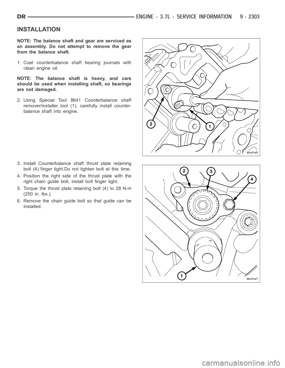
2. Using Special Tool 8641 Counterbalance shaft
remover/installer tool (1), carefully install counter-
balance shaft into engine.
3. Install Counterbalance shaft thrust plate retaining
bolt (4) finger tight.Do not tighten bolt at this time.
4. Position the right side of the thrust plate with the
right chain guide bolt, install bolt finger tight.
5. Torque the thrust plate retaining bolt (4) to 28 Nꞏm
(250 in. lbs.).
6. Remove the chain guide bolt so that guide can be
installed.
Page 1614 of 5267
COVER-TIMING
REMOVAL
1. Disconnect the battery negative cable.
2. Drain cooling system (Refer to 7 - COOLING -
STANDARD PROCEDURE).
3. Remove electric cooling fan and fan shroud assem-
bly.
4. Remove fan and fan drive assembly (Refer to 7 -
COOLING/ENGINE/FAN DRIVE VISCOUS
CLUTCH - REMOVAL).
5. Disconnect both heater hoses at timing cover.
6. Disconnect lower radiator hose at engine.
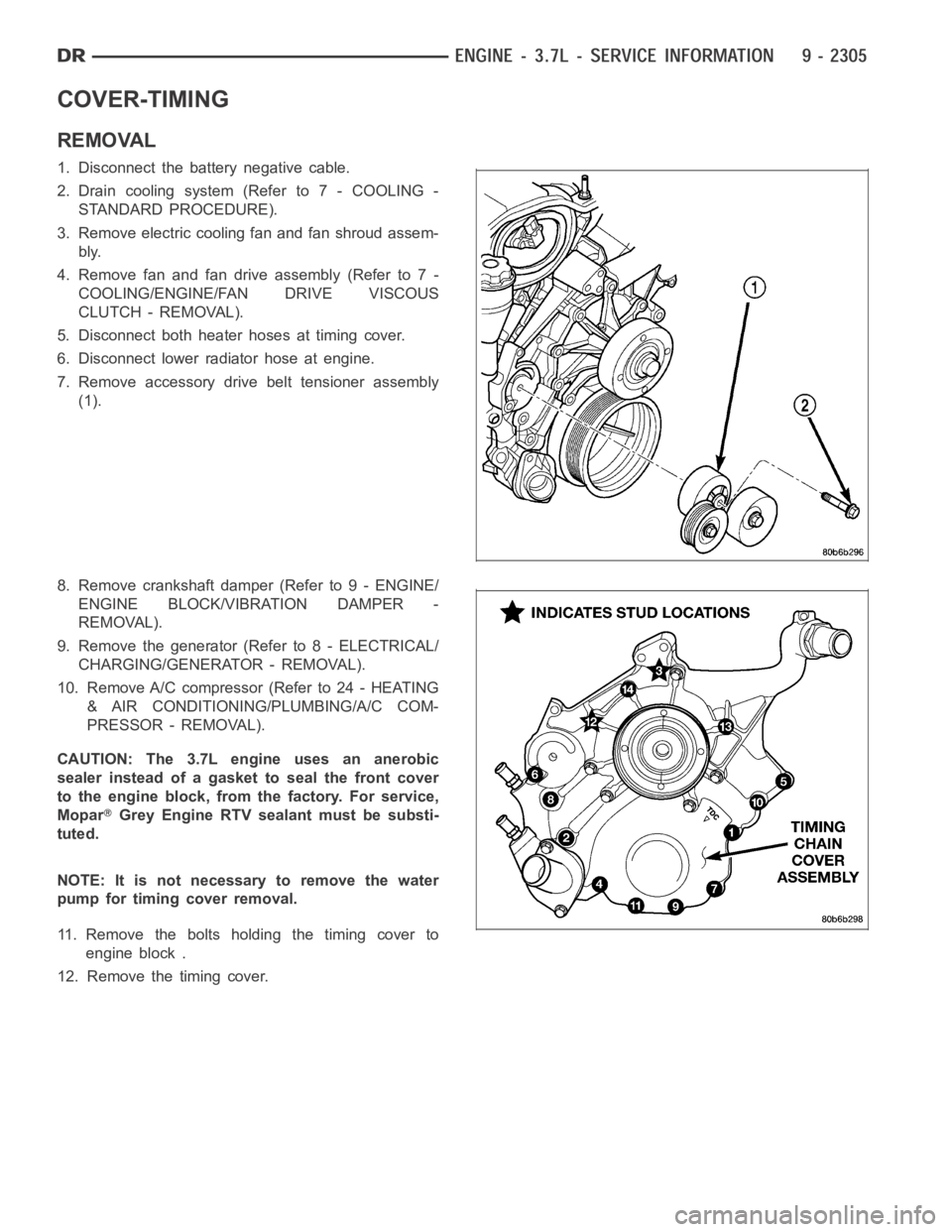
7. Remove accessory drive belt tensioner assembly
(1).
8. Remove crankshaft damper (Refer to 9 - ENGINE/
ENGINE BLOCK/VIBRATION DAMPER -
REMOVAL).
9. Remove the generator (Refer to 8 - ELECTRICAL/
CHARGING/GENERATOR - REMOVAL).
10. Remove A/C compressor (Refer to 24 - HEATING
& AIR CONDITIONING/PLUMBING/A/C COM-
PRESSOR - REMOVAL).
CAUTION: The 3.7L engine uses an anerobic
sealer instead of a gasket to seal the front cover
to the engine block, from the factory. For service,
Mopar
Grey Engine RTV sealant must be substi-
tuted.
NOTE: It is not necessary to remove the water
pump for timing cover removal.
11. Remove the bolts holding the timing cover to
engine block .
12. Remove the timing cover.
Page 1615 of 5267
INSTALLATION
CAUTION: Do not use oil based liquids to clean
timing cover or block surfaces. Use only rubbing
alcohol, along with plastic or wooden scrapers.
Use no wire brushes or abrasive wheels or metal
scrapers, or damage to surfaces could result.
1. Clean timing chain cover and block surface using
rubbing alcohol.
CAUTION: The 3.7L uses a special anerobic sealer
instead of a gasket to seal the timing cover to the
engine block, from the factory. For service repairs,
Mopar
Engine Grey RTV must be used as a sub-
stitute.
2. Inspect the water passage o-rings for any damage,
and replace as necessary.
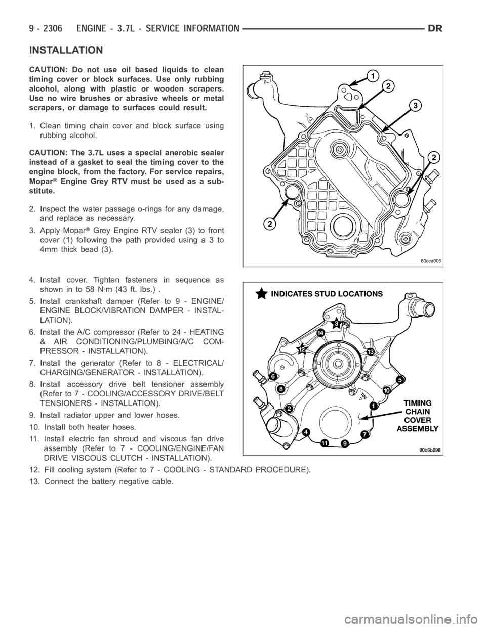
3. Apply Mopar
Grey Engine RTV sealer (3) to front
cover(1)followingthepathprovidedusinga3to
4mm thick bead (3).
4. Install cover. Tighten fasteners in sequence as
showninto58Nꞏm(43ft.lbs.).
5. Install crankshaft damper (Refer to 9 - ENGINE/
ENGINE BLOCK/VIBRATION DAMPER - INSTAL-
LATION).
6. Install the A/C compressor (Refer to 24 - HEATING
& AIR CONDITIONING/PLUMBING/A/C COM-
PRESSOR - INSTALLATION).
7. Install the generator (Refer to 8 - ELECTRICAL/
CHARGING/GENERATOR - INSTALLATION).
8. Install accessory drive belt tensioner assembly
(Refer to 7 - COOLING/ACCESSORY DRIVE/BELT
TENSIONERS - INSTALLATION).
9. Install radiator upper and lower hoses.
10. Install both heater hoses.
11. Install electric fan shroud and viscous fan drive
assembly (Refer to 7 - COOLING/ENGINE/FAN
DRIVE VISCOUS CLUTCH - INSTALLATION).
12. Fill cooling system (Refer to 7 - COOLING - STANDARD PROCEDURE).
13. Connect the battery negative cable.
Page 1623 of 5267
page page
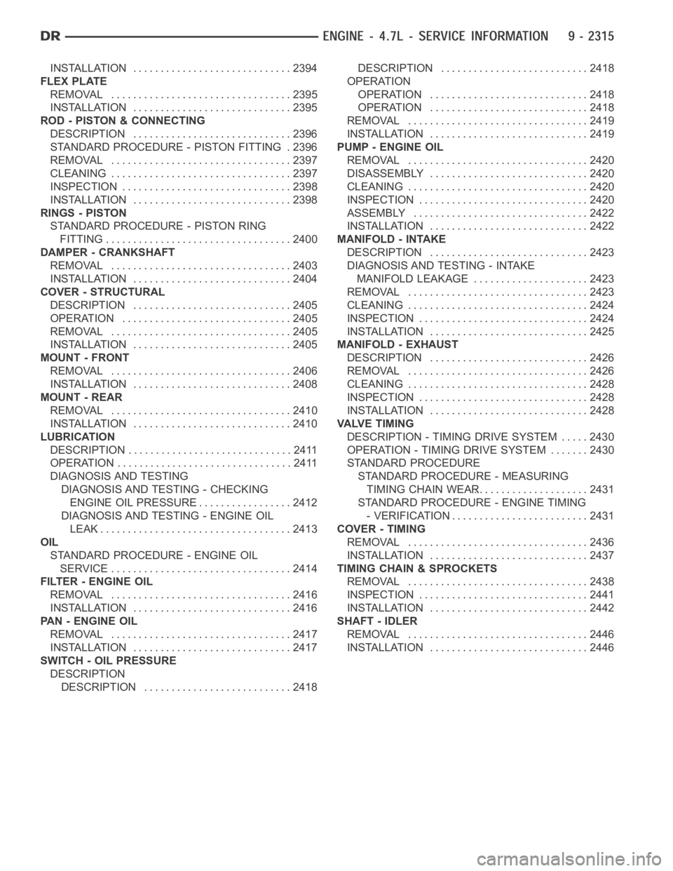
ENGINE - 4.7L - SERVICE INFORMATION
DIAGNOSIS AND TESTING
DIAGNOSIS AND TESTING - ENGINE
DIAGNOSIS - PERFORMANCE............. 2316
DIAGNOSIS AND TESTING - ENGINE
DIAGNOSIS - MECHANICAL............... 2318
DIAGNOSIS AND TESTING - CYLINDER
COMPRESSION PRESSURE............... 2318
DIAGNOSIS AND TESTING - CYLINDER
COMBUSTION PRESSURE LEAKAGE...... 2319
DIAGNOSIS AND TESTING - ENGINE
DIAGNOSIS - INTRODUCTION............. 2320
STANDARD PROCEDURE
STANDARD PROCEDURE - REPAIR
DAMAGED OR WORN THREADS.......... 2320
STANDARD PROCEDURE - FORM-IN-
PLACE GASKETS AND SEALERS.......... 2320
REMOVAL ................................. 2321
INSTALLATION ............................. 2327
SPECIFICATIONS
SPECIFICATIONS - 4.7L ENGINE .......... 2331
TORQUE ................................. 2336
SPECIAL TOOLS
4.7L ENGINE ............................. 2338
ELEMENT - AIR CLEANER
REMOVAL ................................. 2342
INSTALLATION ............................. 2343
CYLINDER HEAD
DESCRIPTION
DESCRIPTION - CYLINDER HEAD ......... 2344
DESCRIPTION - VALVE GUIDES ........... 2344
DIAGNOSIS AND TESTING
CYLINDER HEAD GASKET................ 2344
REMOVAL
REMOVAL - LEFT CYLINDER HEAD ........ 2345
REMOVAL - RIGHT CYLINDER HEAD ...... 2348
CLEANING ................................. 2350
INSPECTION ............................... 2350
INSTALLATION
INSTALLATION - LEFT CYLINDER HEAD . . . 2351
INSTALLATION - RIGHT CYLINDER HEAD . . 2353
CAMSHAFT - LEFT
DESCRIPTION ............................. 2357
REMOVAL ................................. 2357
INSTALLATION ............................. 2359
CAMSHAFT - RIGHT
DESCRIPTION ............................. 2362
REMOVAL ................................. 2362
INSTALLATION ............................. 2365
COVER - CYLINDER HEAD
DESCRIPTION ............................. 2369REMOVAL
REMOVAL - RIGHT SIDE .................. 2369
REMOVAL - LEFT SIDE ................... 2369
CLEANING ................................. 2369
INSTALLATION
INSTALLATION - RIGHT SIDE .............. 2370
INSTALLATION - LEFT SIDE ............... 2370
VALVES & SEATS - INTAKE/EXHAUST
DESCRIPTION ............................. 2371
REMOVAL ................................. 2371
INSTALLATION ............................. 2372
ROCKER ARM - VALVE
DESCRIPTION ............................. 2374
DIAGNOSIS AND TESTING - HYDRAULIC
LASH ADJUSTER ......................... 2374
REMOVAL ................................. 2374
INSTALLATION ............................. 2375
SPRINGS-VALVE
DESCRIPTION ............................. 2376
REMOVAL ................................. 2376
INSTALLATION ............................. 2377
SEALS-VALVE GUIDE
DESCRIPTION ............................. 2378
ENGINE BLOCK
DESCRIPTION ............................. 2379
STANDARD PROCEDURE - CYLINDER BORE
HONING ................................. 2379
CLEANING ................................. 2379
INSPECTION............................... 2380
BEARINGS - CONNECTING ROD
STANDARD PROCEDURE - CONNECTING
ROD BEARING FITTING ................... 2381
PLUGS - CORE
REMOVAL ................................. 2384
INSTALLATION ............................. 2384
CRANKSHAFT
DESCRIPTION ............................. 2385
REMOVAL ................................. 2385
INSPECTION............................... 2386
INSTALLATION ............................. 2386
BEARINGS - CRANKSHAFT MAIN
STANDARD PROCEDURE - CRANKSHAFT
MAIN BEARING - FITTING ................. 2389
INSPECTION............................... 2390
SEAL - CRANKSHAFT OIL - FRONT
REMOVAL ................................. 2391
INSTALLATION ............................. 2392
SEAL - CRANKSHAFT OIL - REAR
DIAGNOSIS AND TESTING - REAR SEAL
AREA LEAKS . ............................ 2393
REMOVAL ................................. 2393
Page 1624 of 5267
INSTALLATION ............................. 2394
FLEX PLATE
REMOVAL ................................. 2395
INSTALLATION ............................. 2395
ROD - PISTON & CONNECTING
DESCRIPTION ............................. 2396
STANDARD PROCEDURE - PISTON FITTING . 2396
REMOVAL ................................. 2397
CLEANING ................................. 2397
INSPECTION ............................... 2398
INSTALLATION ............................. 2398
RINGS - PISTON
STANDARD PROCEDURE - PISTON RING
FITTING .................................. 2400
DAMPER - CRANKSHAFT
REMOVAL ................................. 2403
INSTALLATION ............................. 2404
COVER - STRUCTURAL
DESCRIPTION ............................. 2405
OPERATION ............................... 2405
REMOVAL ................................. 2405
INSTALLATION ............................. 2405
MOUNT - FRONT
REMOVAL ................................. 2406
INSTALLATION ............................. 2408
MOUNT - REAR
REMOVAL ................................. 2410
INSTALLATION ............................. 2410
LUBRICATION
DESCRIPTION .............................. 2411
OPERATION ................................ 2411
DIAGNOSIS AND TESTING
DIAGNOSIS AND TESTING - CHECKING
ENGINE OIL PRESSURE.................. 2412
DIAGNOSIS AND TESTING - ENGINE OIL
LEAK.................................... 2413
OIL
STANDARD PROCEDURE - ENGINE OIL
SERVICE ................................. 2414
FILTER - ENGINE OIL
REMOVAL ................................. 2416
INSTALLATION ............................. 2416
PAN - ENGINE OIL
REMOVAL ................................. 2417
INSTALLATION ............................. 2417
SWITCH - OIL PRESSURE
DESCRIPTION
DESCRIPTION ........................... 2418DESCRIPTION ........................... 2418
OPERATION
OPERATION ............................. 2418
OPERATION ............................. 2418
REMOVAL ................................. 2419
INSTALLATION ............................. 2419
PUMP - ENGINE OIL
REMOVAL ................................. 2420
DISASSEMBLY . ............................ 2420
CLEANING ................................. 2420
INSPECTION............................... 2420
ASSEMBLY................................ 2422
INSTALLATION ............................. 2422
MANIFOLD - INTAKE
DESCRIPTION ............................. 2423
DIAGNOSIS AND TESTING - INTAKE
MANIFOLD LEAKAGE ..................... 2423
REMOVAL ................................. 2423
CLEANING ................................. 2424
INSPECTION............................... 2424
INSTALLATION ............................. 2425
MANIFOLD - EXHAUST
DESCRIPTION ............................. 2426
REMOVAL ................................. 2426
CLEANING ................................. 2428
INSPECTION............................... 2428
INSTALLATION ............................. 2428
VALVE TIMING
DESCRIPTION - TIMING DRIVE SYSTEM ..... 2430
OPERATION - TIMING DRIVE SYSTEM....... 2430
STANDARD PROCEDURE
STANDARD PROCEDURE - MEASURING
TIMING CHAIN WEAR..................... 2431
STANDARD PROCEDURE - ENGINE TIMING
- VERIFICATION.......................... 2431
COVER - TIMING
REMOVAL ................................. 2436
INSTALLATION ............................. 2437
TIMING CHAIN & SPROCKETS
REMOVAL ................................. 2438
INSPECTION............................... 2441
INSTALLATION ............................. 2442
SHAFT - IDLER
REMOVAL ................................. 2446
INSTALLATION ............................. 2446
Page 1625 of 5267
ENGINE - 4.7L - SERVICE INFORMATION
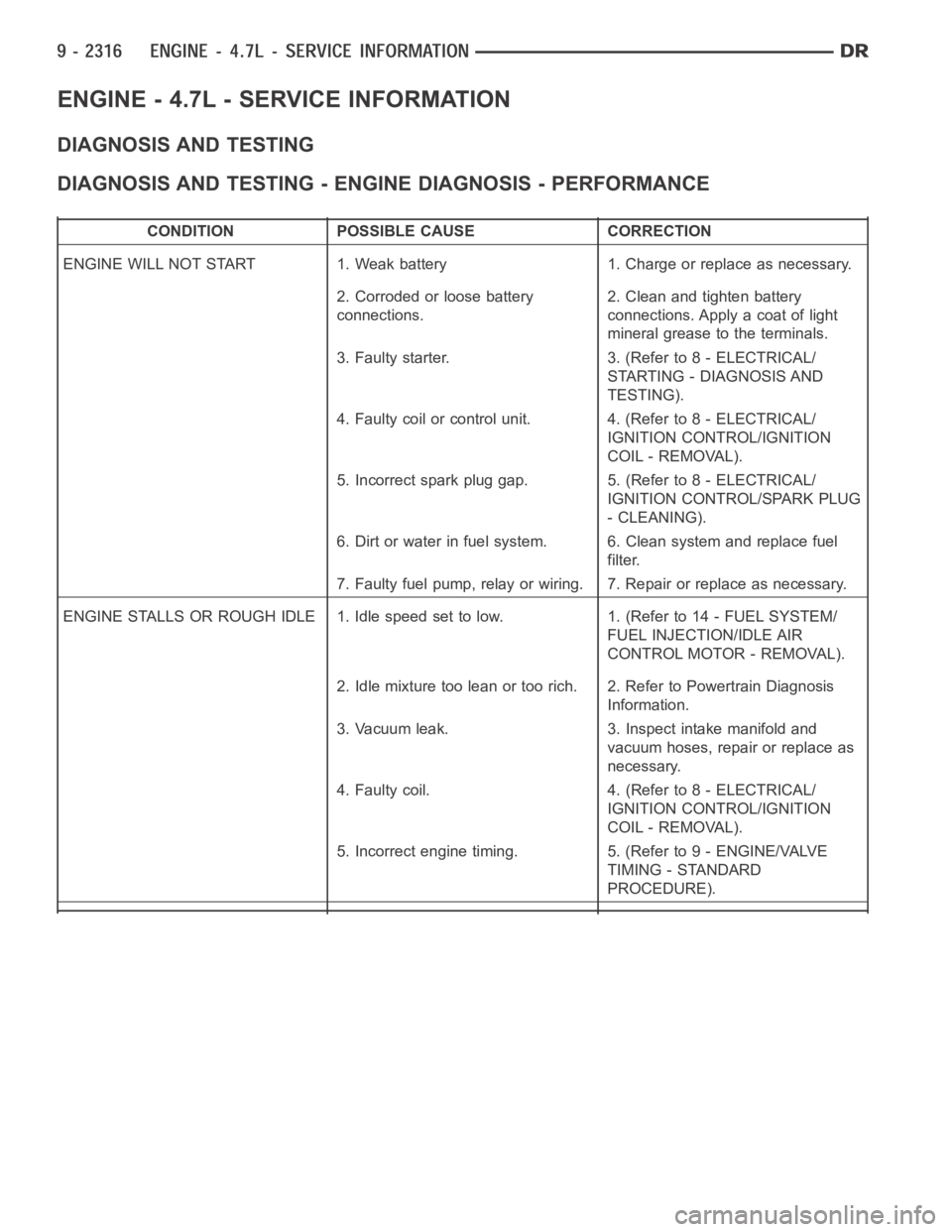
DIAGNOSIS AND TESTING
DIAGNOSIS AND TESTING - ENGINE DIAGNOSIS - PERFORMANCE
CONDITION POSSIBLE CAUSE CORRECTION
ENGINE WILL NOT START 1. Weak battery 1. Charge or replace as necessary.
2. Corroded or loose battery
connections.2. Clean and tighten battery
connections. Apply a coat of light
mineral grease to the terminals.
3. Faulty starter. 3. (Refer to 8 - ELECTRICAL/
STARTING - DIAGNOSIS AND
TESTING).
4. Faulty coil or control unit. 4. (Refer to 8 - ELECTRICAL/
IGNITION CONTROL/IGNITION
COIL - REMOVAL).
5. Incorrect spark plug gap. 5. (Refer to 8 - ELECTRICAL/
IGNITION CONTROL/SPARK PLUG
- CLEANING).
6. Dirt or water in fuel system. 6. Clean system and replace fuel
filter.
7. Faulty fuel pump, relay or wiring. 7. Repair or replace as necessary.
ENGINE STALLS OR ROUGH IDLE 1. Idle speed set to low. 1. (Refer to 14 - FUEL SYSTEM/
FUEL INJECTION/IDLE AIR
CONTROL MOTOR - REMOVAL).
2. Idle mixture too lean or too rich. 2. Refer to Powertrain Diagnosis
Information.
3. Vacuum leak. 3. Inspect intake manifold and
vacuum hoses, repair or replace as
necessary.
4. Faulty coil. 4. (Refer to 8 - ELECTRICAL/
IGNITION CONTROL/IGNITION
COIL - REMOVAL).
5. Incorrect engine timing. 5. (Refer to 9 - ENGINE/VALVE
TIMING - STANDARD
PROCEDURE).
Page 1627 of 5267
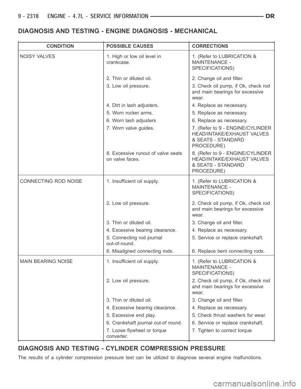
DIAGNOSIS AND TESTING - ENGINE DIAGNOSIS - MECHANICAL
CONDITION POSSIBLE CAUSES CORRECTIONS
NOISY VALVES 1. High or low oil level in
crankcase.1. (Refer to LUBRICATION &
MAINTENANCE -
SPECIFICATIONS)
2. Thin or diluted oil. 2. Change oil and filter.
3. Low oil pressure. 3. Check oil pump, if Ok, check rod
and main bearings for excessive
wear.
4. Dirt in lash adjusters. 4. Replace as necessary.
5. Worn rocker arms. 5. Replace as necessary.
6. Worn lash adjusters 6. Replace as necessary.
7. Worn valve guides. 7. (Refer to 9 - ENGINE/CYLINDER
HEAD/INTAKE/EXHAUST VALVES
& SEATS - STANDARD
PROCEDURE)
8. Excessive runout of valve seats
on valve faces.8. (Refer to 9 - ENGINE/CYLINDER
HEAD/INTAKE/EXHAUST VALVES
& SEATS - STANDARD
PROCEDURE)
CONNECTING ROD NOISE 1. Insufficient oil supply. 1. (Refer to LUBRICATION&
MAINTENANCE -
SPECIFICATIONS)
2. Low oil pressure. 2. Check oil pump, if Ok, check rod
and main bearings for excessive
wear.
3. Thin or diluted oil. 3. Change oil and filter.
4. Excessive bearing clearance. 4. Replace as necessary.
5. Connecting rod journal
out-of-round.5. Service or replace crankshaft.
6. Misaligned connecting rods. 6. Replace bent connecting rods.
MAIN BEARING NOISE 1. Insufficient oil supply. 1. (Refer to LUBRICATION &
MAINTENANCE -
SPECIFICATIONS)
2. Low oil pressure. 2. Check oil pump, if Ok, check rod
and main bearings for excessive
wear.
3. Thin or diluted oil. 3. Change oil and filter.
4. Excessive bearing clearance. 4. Replace as necessary.
5. Excessive end play. 5. Check thrust washers for wear.
6. Crankshaft journal out-of round. 6. Service or replace crankshaft.
7. Loose flywheel or torque
converter.7. Tighten to correct torque
DIAGNOSIS AND TESTING - CYLINDER COMPRESSION PRESSURE
The results of a cylinder compressionpressure test can be utilized to diagnose several engine malfunctions.
Page 1629 of 5267
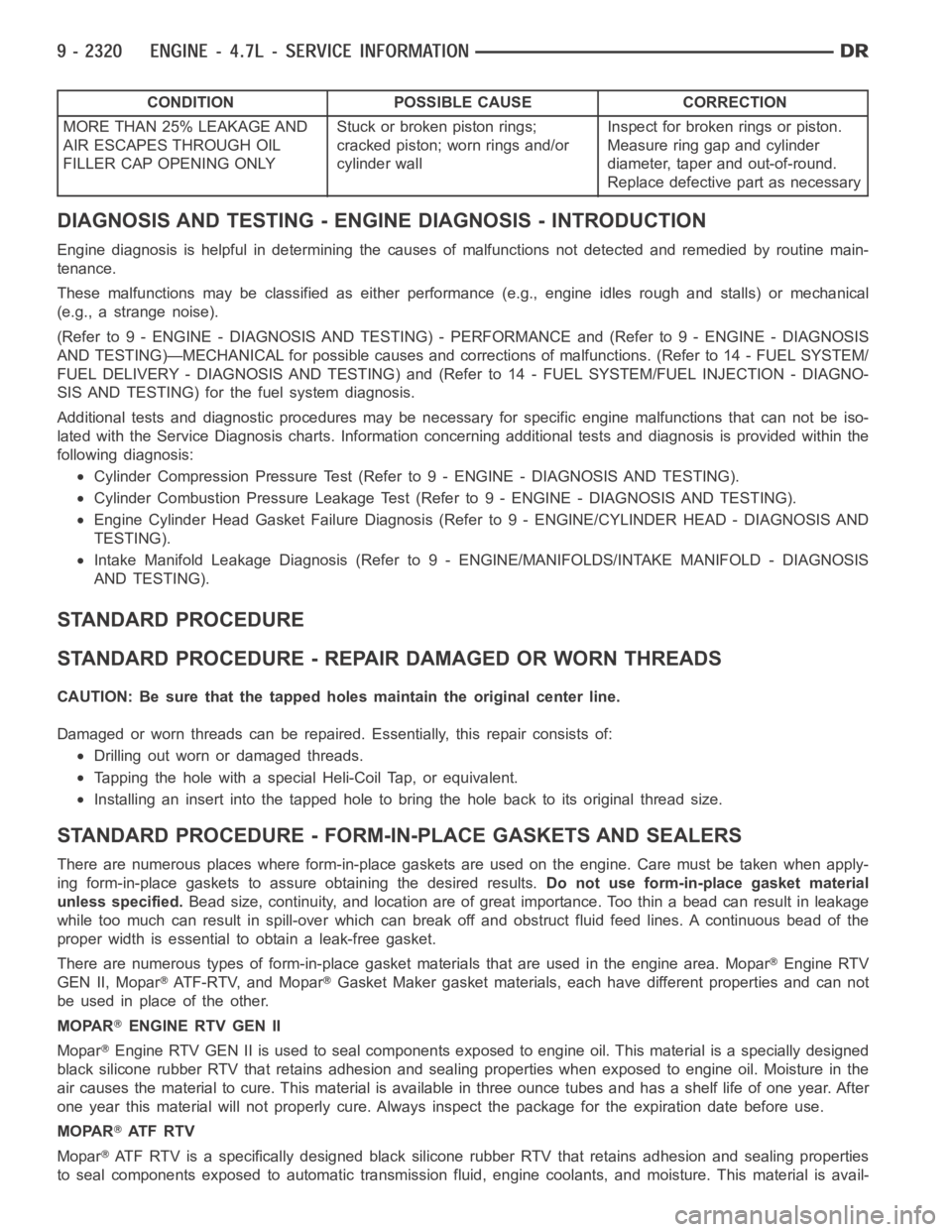
CONDITION POSSIBLE CAUSE CORRECTION
MORE THAN 25% LEAKAGE AND
AIR ESCAPES THROUGH OIL
FILLER CAP OPENING ONLYStuckorbrokenpistonrings;
cracked piston; worn rings and/or
cylinder wallInspect for broken rings or piston.
Measure ring gap and cylinder
diameter, taper and out-of-round.
Replace defective part as necessary
DIAGNOSIS AND TESTING - ENGINE DIAGNOSIS - INTRODUCTION
Engine diagnosis is helpful in determining the causes of malfunctions notdetected and remedied by routine main-
tenance.
These malfunctions may be classified as either performance (e.g., engineidles rough and stalls) or mechanical
(e.g., a strange noise).
(Refer to 9 - ENGINE - DIAGNOSIS AND TESTING) - PERFORMANCE and (Refer to 9 - ENGINE - DIAGNOSIS
AND TESTING)—MECHANICAL for possible causes and corrections of malfunctions. (Refer to 14 - FUEL SYSTEM/
FUEL DELIVERY - DIAGNOSIS AND TESTING) and (Refer to 14 - FUEL SYSTEM/FUEL INJECTION - DIAGNO-
SIS AND TESTING) for the fuel system diagnosis.
Additional tests and diagnostic procedures may be necessary for specificengine malfunctions that can not be iso-
lated with the Service Diagnosis charts. Information concerning additional tests and diagnosis is provided within the
following diagnosis:
Cylinder Compression Pressure Test (Refer to 9 - ENGINE - DIAGNOSIS AND TESTING).
Cylinder Combustion Pressure LeakageTest (Refer to 9 - ENGINE - DIAGNOSISAND TESTING).
Engine Cylinder Head Gasket Failure Diagnosis (Refer to 9 - ENGINE/CYLINDER HEAD - DIAGNOSIS AND
TESTING).
Intake Manifold Leakage Diagnosis (Refer to 9 - ENGINE/MANIFOLDS/INTAKEMANIFOLD - DIAGNOSIS
AND TESTING).
STANDARD PROCEDURE
STANDARD PROCEDURE - REPAIR DAMAGED OR WORN THREADS
CAUTION: Be sure that the tapped holes maintain the original center line.
Damaged or worn threads can be repaired. Essentially, this repair consistsof:
Drilling out worn or damaged threads.
Tapping the hole with a special Heli-Coil Tap, or equivalent.
Installing an insert into the tapped hole to bring the hole back to its original thread size.
STANDARD PROCEDURE - FORM-IN-PLACE GASKETS AND SEALERS
There are numerous places where form-in-place gaskets are used on the engine. Care must be taken when apply-
ing form-in-place gaskets to assure obtaining the desired results.Do not use form-in-place gasket material
unless specified.Bead size, continuity, and location are of great importance. Too thin a bead can result in leakage
while too much can result in spill-overwhich can break off and obstruct fluid feed lines. A continuous bead of the
proper width is essential to obtain a leak-free gasket.
There are numerous types of form-in-place gasket materials that are used in the engine area. Mopar
Engine RTV
GEN II, Mopar
ATF-RTV, and MoparGasket Maker gasket materials, each have different properties and can not
be used in place of the other.
MOPAR
ENGINE RTV GEN II
Mopar
Engine RTV GEN II is used to seal components exposed to engine oil. This material is a specially designed
black silicone rubber RTV that retains adhesion and sealing properties when exposed to engine oil. Moisture in the
air causes the material to cure. This material is available in three ounce tubes and has a shelf life of one year. After
one year this material will not properly cure. Always inspect the package for the expiration date before use.
MOPAR
AT F R T V
Mopar
ATF RTV is a specifically designed black silicone rubber RTV that retains adhesion and sealing properties
to seal components exposed to automatic transmission fluid, engine coolants, and moisture. This material is avail-